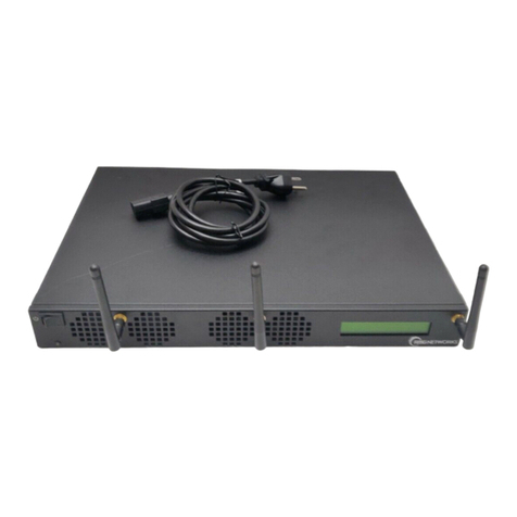
RMG NETWORKS IVS SDA-909 User manual

IVS SDA-909
Mounting and
Connections

2
Notice
Copyright © 2013 RMG Enterprise Solutions, Inc. All Rights Reserved.
This publication is protected by copyright and all rights are reserved. No part of this
book may be reproduced or transmitted by any means or in any form, without prior
written consent from RMG Enterprise Solutions, Inc.
The information in this publication has been carefully checked and is believed to be
accurate. RMG Enterprise Solutions, Inc. assumes no liability for any inaccuracies that
may be found in this publication.
In the interest of continued product development, RMG Enterprise Solutions, Inc.
reserves the right to make improvements to this publication and the products it
describes at any time without notice or obligation.
Publication Date
RMGN-DOC-IVS-SDA-909-121213 cmgpdf-121213 December 2013
To access the latest version of this document, go to:
http://support.rmgnetworks.com/documentation/IVS_SDA-909_Mounting-and-
Connections.pdf

3
Contents
FCC Verification, Industry Canada & European CE Information . . . . . . 4
FCC . . . . . . . . . . . . . . . . . . . . . . . 4
Industry Canada . . . . . . . . . . . . . . . . . . . 4
Important Safety Instructions . . . . . . . . . . . . . . . . . . . . 5
Mounting the IVS SDA-909 . . . . . . . . . . . . . . . . . . . . . 6
Attaching the Mounting Plate . . . . . . . . . . . . . . . 7
Simple Wall Mount . . . . . . . . . . . . . . . . . . . 8
VESA-Compliant Display Mount . . . . . . . . . . . . . . 9
Connecting the IVS SDA-909 . . . . . . . . . . . . . . . . . . . . 12
IVS SDA-909 Diagram. . . . . . . . . . . . . . . . . . 12
Step-by-Step Connections for the IVS SDA-909 . . . . . . . . . 14
IVS SDA-909 Specifications . . . . . . . . . . . . . . . . . . . . . 15
Physical Dimensions . . . . . . . . . . . . . . . . . . 15
Hardware Components . . . . . . . . . . . . . . . . . 20
Power Requirements . . . . . . . . . . . . . . . . . . 21
Operating Specifications . . . . . . . . . . . . . . . . . 21
Getting Help and Support . . . . . . . . . . . . . . . . . . . . . . 22
Contacting Technical Support . . . . . . . . . . . . . . . 22
Accessing the RMG Networks Support Web Site . . . . . . . . . 22

4
FCC Verification, Industry Canada & European CE Information
FCC
This equipment has been tested and found to comply with the limits for a Class A
digital device, pursuant to part 15 of the FCC rules. These limits are designed to
provide reasonable protection against harmful interference when the equipment is
operated in a commercial environment. This equipment generates, uses, and can
radiate radio frequency energy and, if not installed and used in accordance with the
instruction manual, may cause harmful interference to radio communications.
Operation of this equipment in a residential area is likely to cause harmful interference,
in which case the user will be required to correct the interference at his own expense.
WARNING: Changes or modifications to this device not expressly approved by
RMG Networks could void the user's authority to operate the equipment.
Industry Canada
This Class A digital apparatus meets all requirements of the Canadian Interference
Causing Equipment Regulations. Operation is subject to the following two conditions:
(1) this device may not cause harmful interference, and
(2) this device must accept any interference received, including interference that may
cause undesired operation.

5
Important Safety Instructions
This device has undergone various tests in order to comply with safety standards.
Inappropriate use may be dangerous. Please follow the instructions in this guide to
ensure your safety during the installation and operation of the device. For safety and
proper operation, keep in mind the following factors:
•It is important that your IVS SDA-909 be properly ventilated. Do not fully enclose
the IVS SDA-909 in any type of recess, cabinet, kiosk, hole, nook, or enclosure
unless there are fans or a passive thermal exhaust that can constantly bring in new
air to replace the trapped air in the space around the outside of the device.
•Place the IVS SDA-909 in a location free from dust and other particles.
•Ambient temperature should be between 32 °F to 104 °F (0 °C to +40 °C) in a non-
condensing environment.
With the above factors in mind, please be aware of the following section from your
hardware maintenance contract:
In the event that Hardware Maintenance is required due to: (i) abuse or
mishandling of the Hardware by Customer, or (ii) any environmental conditions
where the Hardware is located (dust, moisture, etc.), or (iii) any other technical
issues (electrical “spikes” or the like), or (iv) any other external factors outside the
normal operating conditions for the Hardware; then the charges for Maintenance
associated therewith shall be paid by Customer.

6
Mounting the IVS SDA-909
The IVS SDA-909 includes hardware for installing the unit in a simple wall mount
configuration or at the back of a VESA-compliant display. Do not throw away any
cables, adapters, or other hardware that you might receive with the product—you may
need them for future use if you should ever upgrade the IVS SDA-909.
(1) IVS SDA-909 Unit with
Mounting Plate & Screws Attached (1) Power Cord (4) M9 Bolts
(1) Mounting Plate (2) Wireless
Antennas (2) Bracket Screws
PWR
HDD

7
Attaching the Mounting Plate
You can attach the mounting plate to the IVS SDA-909 on either its top or bottom side.
The orientation in which you want to mount the IVS SDA-909 determines which side to
attach the mounting plate.
1. Slide the mounting plate so that the inner loop of the
bracket is in line with the bracket screw in the left-most
position on the IVS SDA-909.
2. Turn the spring-loaded screws on each side clockwise
to secure the mounting plate to the IVS SDA-909.
PWR
HDD
Mounting Plate Attached to
Bottom of IVS SDA-909
PWR
HDD
Mounting Plate Attached to
Top of IVS SDA-909
1
v
v
2

8
Simple Wall Mount
To install the IVS SDA-909 on a wall,
position the unit so that the Power
Button is on the bottom-side of the unit
and the connections are on top. This
allows the Power Button to be easily
accessible from below, and the heat from
the exhaust vents can rise above the unit.
1. Align the flat side of the mounting
plate against the wall area where you
want to install the IVS SDA-909.
2. Use four screws (not supplied) to attach the mounting
plate to the wall.
3. Attach the IVS SDA-909 to the mounting plate using the
steps on page 7.
4. (Optional) If you are using wireless communications,
attach the two antennas to the connections at the top of
the unit. (Pages 17 and 18 illustrate the space
requirements for the antennas when fully extended or
bent at a 90° angle.)
5. Refer to the instructions on page 12 to connect
the IVS SDA-909.
It is important that your IVS SDA-909 be properly ventilated and placed in a
location with the ambient temperature between 32 °F to 104 °F (0 °C to +40
°C). See page 5 for specific details.
100-240VAC
50/60Hz
1.3-0.8A
Power Button
on Bottom
Connections
on Top
Exhaust Vents
Leave antennas
fully extended or
bend to 90°.
100-240VAC
50/60Hz
1.3-0.8A
FIGURE 1. Simple Wall
Mount

9
VESA-Compliant Display Mount
The IVS SDA-909 mounting plate is
compatible for mounting against the
back of a display that has a 75 mm x
75 mm or 100 mm x 100 mm VESA
MIS-D hole mount pattern. Use the hole
mount pattern on the mounting plate
that matches the pattern on the back of
your display.
FIGURE 2. 75 mm x 75 mm and
100 mm x 100 mm hole mount patterns
1. Position the mounting plate against the
back of the display at the location
where you want to mount the IVS
SDA-909.
It is important that your IVS SDA-909 be properly ventilated and placed in a
location with the ambient temperature between 32 °F to 104 °F (0 °C to +40
°C). See page 5 for specific details.
100 mm
100 mm
100 mm
75 mm
75 mm
75 mm
75 mm
100 mm

10
2. Use a Phillips screwdriver and four M9
bolts (supplied) to secure the mounting
plate to the back of the display.
3. Attach the IVS SDA-909 to the mounting plate using the steps on page 7.
Note: Position the unit so that the Power Button is on the bottom-side of the unit
and the connections are on top. This allows the Power Button to be easily
accessible from below, and the heat from the exhaust vents can rise above the
unit.
Connections
on Top
Exhaust Vents
Power Button on
Bottom

11
4. (Optional) If you are using wireless
communications, attach the two
antennas to the connections at the top
of the unit. (Pages 17 and 18 illustrate
the space requirements for the
antennas when fully extended or bent
at a 90° angle.)
FIGURE 3. VESA-Compliant
Display Mount
Leave antennas
fully extended or
bend to 90°.

12
Connecting the IVS SDA-909
IVS SDA-909 Diagram
The following diagram demonstrates how to connect your IVS SDA-909 model. (A key
to the numbered parts is shown in Table 1 on page 13.)
FIGURE 4. IVS SDA-909 Connections
Right Side ViewFront View
PWR
HDD
3
4
5
Back View
100-240VAC
50/60 Hz
1.3-0.8A
IOIOI
68a 8b
11 12
1
2a
9a
10 9b
7
v
Left Side View
2b13

13
TABLE 1: IVS SDA-909 Functions
Item # Description
1 USB 2.0 x (2)
2a, 2b Intake Vents
3 Power Indicator (White)
4 Power Button
5 HDD Indicator (Blue)
6ACInput
7 RS-232 Serial Connector
8a, 8b Wireless Antenna Connectors
9a, 9b Exhaust Vents
10 USB 2.0 x (2)
11 HDMI Connectors x (2)
12 10/100/1000 Gigabit Ethernet Connector
13 Kensington Lock

14
Step-by-Step Connections for the IVS SDA-909
Warning: Failure to set up your IVS SDA-909 sequentially according to the steps below
may cause configuration difficulties or loss of functionality.
Refer to Figure 4 on page 12 for the following connections:
1. Insert a standard Ethernet cable into the Ethernet port (12).
2. The IVS SDA-909 supports one HDMI-to-HDMI output connection.
Connect the male end of an HDMI-to-HDMI cable (not supplied) to an HDMI
connector (11) at the back of the IVS SDA-909. Connect the other end of the cable
to an HDMI connector on a display device.
3. Connect the female end of the power cord to the three-prong connection at the
back of the IVS SDA-909 (6). Plug the other end of the power cord into a standard
AC outlet.
4. Briefly press the power button (4) on the IVS SDA-909. The SDA welcome
message appears on the output screen.
Note: The first time you connect your SDA, the message “One Moment Please”
may appear on the video display. Depending on your network, this message might
appear for up to one minute. After that time a “Welcome” screen appears that
displays the name of the SDA, its serial number, and the IP address that you'll need
to set up your SDA. Use this IP address to access the Web Interface.
5. Refer to the following SDA configuration guide to configure your IVS SDA-909:
http://support.rmgnetworks.com/documentation/IVS_SDA_Configuration_v12.0.2.pdf

15
IVS SDA-909 Specifications
Physical Dimensions
Without Antennas or Mounting Plate
Dimensions (W) x (H) x (D):
165.1 mm x 41.28 mm x 108 mm
(6.50” x 1.625” x 4.25”)
Weight: .90 kg (1 lb., 15.8 oz.)
165.1 mm
(6.5")
41.28 mm
(1.625")
100-240VAC
50/60 Hz
1.3-0.8A
IOIOI
Back View
Front View
PWR
HDD
165.1 mm
(6.5")
41.28 mm
(1.625")

16
Right Side View
108 mm
(4.25")
41.28 mm
(1.625")
117.48 mm
(4.625")
9.5 mm
(.375")
v
Left Side View
108 mm
(4.25")
41.28 mm
(1.625")
117.48 mm
(4.625")
9.5 mm
(.375")

17
With Mounting Plate & Antennas Fully Extended
Dimensions (W) x (H) x (D):
165.1 mm x 41.28 mm x 222.25 mm
(6.5” x 1.625” x 8.757”)
Weight: 1.07 kg (2 lbs., 5.8 oz.)
Left Side View with Antennas Fully Extended
v
108 mm
(4.25")
41.28 mm
(1.625")
6.35 mm
(.25")
47.625 mm
(1.875")
47.625 mm
(1.875")
114.3 mm
(4.5")
108 mm
(4.25")

18
With Mounting Plate & Antennas Bent at 90°
Dimensions (W) x (H) x (D):
166 mm x 95 mm x 194 mm
(6.53” x 3.75” x 7.625”)
Weight: 1.07 kg (2 lbs., 5.8 oz.)
Left Side View with Antennas Bent 90°
6.35 mm
(.25")
22.23 mm
(.875")
85.725 mm
(3.375")
114.3 mm
(4.5")
108 mm
(4.25")
v
41.28 mm
(1.625")
47.625 mm
(1.875")
47.625 mm
(1.875")

19
With Mounting Plate
Dimensions (W) x (H) x (D):
177.8 mm x 41.28 mm x 117.5 mm
7.0” x 1.625” x 4.625”)
Weight: 1.05 kg (2 lbs., 5.1 oz.)
165.1 mm
(6.5")
177.8 mm
(7.0")
9.53 mm
(.375")
6.35 mm
(.25")
6.35 mm
(.25")
Top View with Mounting Plate
108 mm
(4.25")
117.5 mm
(4.625")

20
Hardware Components
Front Panel IO
Power Button: x1
Disk Activity Indicator (blue): x1
Power indicator (white): x1
USB 2.0 Port: x2
Audio
Type : HDM I
LAN: 10/100/1000 Gigabit
Rear Panel IO
DC Jack: x1
HDMI port: x2
USB 2.0: x2
Serial DB9 (COM Port): x1 (For RS-232 Screen Control)
Wireless Antenna Connection: 802.11 a,b,g,n (2 x rear external
antennas)
Kensington Lock Hole: x1 (side)
Table of contents
Other RMG NETWORKS Media Player manuals
