RMT PAL User manual
OWNERS MANUAL
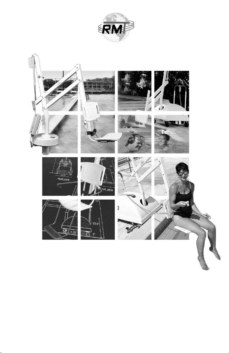
RehaMed Aquatics
The New Standard in Aquatic Lifts!

PAL / PAL Hi-Lo
Product Overview………………………………………………… 4
A. Product Components
– Standard to All Products……………………………………… 5
–PAL Base Assembly………………………………………….. 6
B. Unpacking & Assembly Instructions- PAL………………………. 7-9
Splash! / Splash! Hi-Lo / Splash! HD / Splash! Mariner
Product Overview………………………………………………… 10
C. Product Components
– Standard to All Products……………………………………… 11
– Splash! Base Assembly……………………………………. 12
D. Unpacking & Assembly Instructions- Splash!……………………. 13-14
– Pool Deck Installation………………………………………… 15
GENERAL - ALL PRODUCTS
E. Battery Charging………………………………………………… 16
F. Remote Control Operation……………………………………… 16
G. Transferring……………………………………………………… 17-18
H. Maintenance……………………………………………………… 18
I. Trouble Shooting………………………………………………… 19
J. Warranty………………………………………………………… 19
K. Product Specifications
– Dimensions/Capacity………………………………………… 20
– Actuator……………………………………………………… 20
– Motor………………………………………………………… 20
– Battery………………………………………………………. 20
– Materials and Finish………………………………………… 21
– Range of Motion……………………………………………… 21
L. Standard/Optional Accessories…………………………………….. 22
M. Parts List………………………………………………………….. 23
TABLE OF CONTENTS
2

The purpose of this document is to provide information relating to the
operation, care, and maintenance of RehaMed International’s line of Aquatic
Lifting Products.
Our goal is to provide our customers with the most advanced and innovative
designs that offer exceptional quality at affordable prices. We design and
manufacture our products so that all individuals with disabilities and mobility
impairments can have access to, and enjoyment from the recreation activity of
their choice. Please feel free to contact us directly if you have any questions
about our current product line or have needs that we may be able to assist you
in meeting in the future.
RehaMed International, LLC.
14008 SW 140th Street • Miami, FL 33186
800-577-4424 Toll Free
305-255-1400 Phone
305-969-2155 Fax
http://www.poollifts.com
INTRODUCTION
CONTACT INFORMATION
3
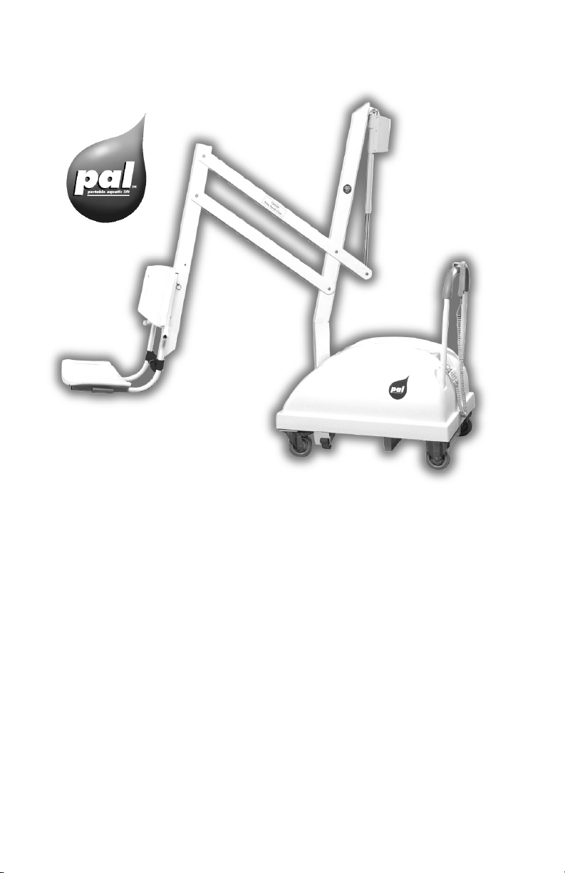
PAL- Product Overview
The PAL-Portable Aquatic Lift is designed to provide the greatest flexibility
for swimming facilities seeking to provide access to more than one pool or
spa, or to accommodate a user’s desire to enter a single pool in multiple
locations. The PAL is completely portable, is battery powered, and is
operated by a screw driven actuator. This design insures consistent operation
and elimination of service problems that occur with water powered pool lifts.
The PAL is available in a Hi-Lo version to accommodate facilities with both
in-ground pools and above-ground spas.
The PAL can be adapted to virtually any pool configuration. A poolside
configuration worksheet is requested with each order prior to shipping so
the lift is configured to match customer’s specifications. If you have
questions regarding the PAL’s adaptability to pool’s configurations,
please contact either your vendor or RehaMed directly.
THE PAL-PORTABLE AQUATIC LIFT
4

5
All PAL and Splash! Products – Standard Components in all Units
Control Box. Forms the bottom of the control console; this unit controls
the mechanical operations of the lift. Three wire leads connect to the rear
of the Control Box. The largest receptacle is the connection for the Hand
Control. The connector next to the hand control connector, marked num-
ber 1, is the receptacle for the Actuator lead. The connector
next to the actuator connector, marked number 2, is the
receptacle for the 24-volt motor lead.
Battery. The removable Battery is located on top of the
control box. The battery should be charged frequently. Do
not allow to fully discharge.
Hand Control. Initiates the actions of the lift. The two top
pairs of buttons control the lifting actions of the unit. The
user can select “fast up/fast down” or “slow up/slow
down” based on their individual comfort level. The bottom
pair of buttons controls the side to side movement of the
lift. The right button turns the main mast to the right, and
the left button turns the main mast to the left.
Mast. This vertical piece is bolted to the base assembly.
Actuator. Attached to the top of the mast, this part powers the up and
down movements of the lift.
Horizontal Support Arms. These two support arms connect the mast to
the chair support arm. The longer horizontal support arm (actuator arm)
connects to the actuator and initiates the lifting movements.
Chair Support Arm. Connects the chair to the horizontal support arms.
Chair Assembly. Connects to the Chair Support Arm.
A– PRODUCT COMPONENTS
REFER TO THE DIAGRAM ON PG.7 FOR COMPONENT IDENTIFICATION.

6
PAL/PALHi-Lo - Base Assembly Only
The Base Assembly is made up of several components as described below:
Casters. These are the wheels on which the PAL moves. The front
wheels are rigid and the back wheels are swivel and locking casters to
facilitate movement of unit.
Main Frame. This is the rectangular piece that is fixed to the casters. The
main frame is made up of several components:
Rotation Motor Assembly. Consists of mounting plate, 24-volt motor,
and small gear.
Hub Assembly. Consists of hub, bearings, shaft, large gear and mast
mounting plate.
Stabilizing Arms. These arms pull out to level the unit and should always
be engaged when the unit is in use.
Counter Weights. These 17 plates weigh approximately 40 pounds each and
are housed in the counter weight receptacle of the main frame. The weights
should be placed horizontally into the receptacle to facilitate handling.
Housing. ABS Plastic covering to cover main frame components from
weather. Needs to be in place prior to installing the mast assembly.
Handle. Connects to the Main Frame through openings in the housing.
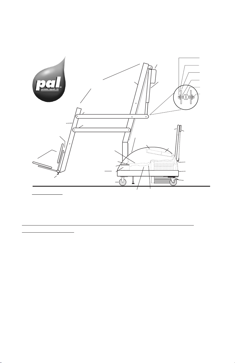
7
Mast
Mast
Assembly
Actuator
SECTION DETAIL
Actuator Assembly
Shaft
Hand Control
Handle
Housing
Weight Plates
Main Frame
Swivel Caster
& Brake
Battery Control
Box
Tie wrap
holder
Actuator
cable
Bolt
24 volt
motor cable
Mast Mounting Plate
Base Assembly
Fixed Caster
Seat Belt Strap
Chair Assembly
Bolt
Support Arm
Actuator Arm
Chair Support Arm
SIDE VIEW
Bolt
Washer
Act. Arm
Spacer
Acturator
Lock Nut
Component Identification
PAL-Portable Aquatic Lifting Systems
B. UNPACKING & ASSEMBLY INSTRUCTIONS
REFER TO THE DIAGRAM (above) FOR PARTS IDENTIFICATION.
READ THESE INSTRUCTIONS IN THEIR ENTIRETY BEFORE
UNCRATING PAL.
Prior to opening the pallet, inspect the external condition for any visible
damage. It is important that any damage be noted on the Bill of Lading.
Contact RehaMed or dealer immediately to notify of missing or damaged
parts.
The PAL is shipped on a cardboard covered pallet. This pallet is VERY
HEAVY. You will need to gather the following tools to begin the unpacking
and assembly of your unit:
• a Phillips head screwdriver or powered drill to remove the cardboard
• a 3/4” socket wrench
• a small flat blade screwdriver
• a knife or cutters to cut the shrink-wrap and bands.

8
IMPORTANT NOTE:
Two people will be needed for completion of step 11.
1. Cut bands and remove long box containing mast from side of cardboard
enclosure.
2. Remove the cardboard enclosure by removing the screws at the bottom and
lifting off the enclosure.
3. Cut bands and remove chair assembly and housing.
4. Remove and unwrap the handle located under the frame.
5. Remove the main frame from the pallet. Position the main frame close to
the pallet and lock the wheels.
6. Carefully transfer the remaining plates (15) from the pallet into the plate
enclosure on the main frame. Each plate weighs approximately 40 pounds
so be careful not to pinch fingers or drop when placing into plate enclosure.
Be sure that the plates lie flat on top of each other. If any plate appears to
rock, remove that plate, flip it over, and replace it into the enclosure.
7. Open box containing mast, remove and unwrap mast assembly. Leave mast
assembly in fully contracted position, this will make handling easier.
8. On frame, cut tie wrap securing 24v motor cable, position cable on top of
counterweights.
9. Remove 2 bolts and lock washers from base assembly.
10. Place housing on frame.
11. Position mast assembly thru housing and attach to mast mounting plate on
base assembly with bolts and lock washers. Fully tighten with 3/4” socket
wrench. This step requires one person to hold the mast assembly while a
second person secures the bolts. Wiggle the mast to make sure the
connection is secure.
12. Cut the bands around mast (WARNING! arms will drop so be careful they
are adequately supported before cutting bands).
13. Extend arm assembly and rest chair support arm on ground; use cardboard
or similar material under chair support arm to prevent scratching.
14. Cut tie wrap and uncoil actuator cable at bottom of mast.
15. Lift and slide the housing part way up the mast to gain access to frame area
under housing.
16. Run actuator cable along with the 24v motor cable across the top of the
weights and insert through the hole in the rear of the housing near the
control box.

9
17. Insert actuator cable (with the “o” ring) into receptacle #1 on the control
box.
18. Insert 24v motor cable into receptacle #2 on control box.
19. Return housing to normal position.
20. Insert handle into slots.
21. Attach actuator to actuator arm using hardware (2 3/4” bolt, nut and 2
plastic spacers) connected to actuator. Place plastic spacers on either side of
actuator on inside of actuator arm. See section detail in diagram page 7.
22. Remove and unwrap hand control from accessory carton. Insert connector
into large receptacle on control unit and hang hand control on handle.
23. Attach battery to control unit mounted on housing.
24. Lock wheels to prevent movement.
25. Raise lift to its highest position.
26. Check the side to side controls for proper operation.
27. Return lift to deck side and move lift away from pool.
28. Attach chair assembly with lock pin into the appropriate hole. To facilitate
storage, chair can be attached facing inward, which will require less space.
Please call RehaMed International at
800-577-4424 if you have any problems
or questions with assembly.

10
SPLASH!- Product Overview
The Splash!-aquatic lifting system is a semi-portable lift system designed for
swimming facilities seeking to provide universal access to their pools. The
Splash! is battery powered and is operated by a screw driven actuator. This
design insures consistent operation and elimination of service problems that
occur with water powered pool lifts. The Splash! is available in a Hi-Lo
version to accommodate facilities with both in-ground pools and above-
ground spas; and a Heavy Duty (HD) model to accommodate up to 375 lbs.
The Splash! Mariner provides access to watercraft and can be mounted to a
floating boat dock. The Splash! Mariner utilizes a sling seat to place the user
onto a boat seat, eliminating the need for transfers. To facilitate moving unit,
an optional caddie can be purchased. The Caddie is designed to lift unit out
from anchor socket and roll to storage or another location if desired. Caddie
also serves as a convenient storage rack for the lift when not in use.
THE SPLASH! –
SEMI-PORTABLE AQUATIC LIFT SYSTEMS
11
All PAL and Splash! Products – Standard Components in all Units
Control Box. Forms the bottom of the control console; this unit controls
the mechanical operations of the lift. Three wire leads connect to the rear
of the Control Box. The largest receptacle is the connection for the Hand
Control. The connector next to the hand control connector, marked num-
ber 1, is the receptacle for the Actuator lead. The connector
next to the actuator connector, marked number 2, is the
receptacle for the 24-volt motor lead.
Battery. The removable Battery is located on top of the
control box. The battery should be charged frequently. Do
not allow to fully discharge.
Hand Control. Initiates the actions of the lift. The two top
pairs of buttons control the lifting actions of the unit. The
user can select “fast up/fast down” or “slow up/slow
down” based on their individual comfort level. The bottom
pair of buttons controls the side to side movement of the
lift. The right button turns the main mast to the right, and
the left button turns the main mast to the left.
Mast. This vertical piece is bolted to the base assembly.
Actuator. Attached to the top of the mast, this part powers the up and
down movements of the lift.
Horizontal Support Arms. These two support arms connect the mast to
the chair support arm. The longer horizontal support arm (actuator arm)
connects to the actuator and initiates the lifting movements.
Chair Support Arm. Connects the chair to the horizontal support arms.
Chair Assembly. Connects to the Chair Support Arm.
C– PRODUCT COMPONENTS
REFER TO THE DIAGRAM ON PG.13 FOR COMPONENT IDENTIFICATION.

12
Splash! / Splash! Hi-Lo / Splash! HD / Splash! Mariner
Base Assembly Only
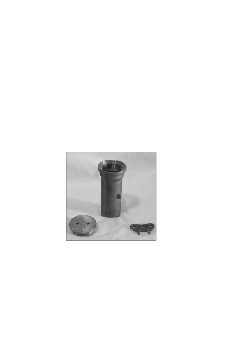
Base Assembly. The part of the Splash! that mounts to the pool deck or
boat dock. The Base Assembly is made up of several components as
described below:
Rotation Motor Assembly. Consists of mounting plate, 24-volt motor,
and small gear.
Hub Assembly. Consists of hub, bearings, shaft, large gear and mast
mounting plate.
Base Insert Stem. This piece slides into the anchor sleeve that is installed
on the pool deck or dock. The insert can either be round or square to
adapt to the designated sleeve.
Control Console Bracket. This tubular component bolts to the base
assembly and provides a mounting base for the control console.
Housing. Aluminum covering to cover base assembly components from
weather. Needs to be in place prior to installing the mast assembly.
Attachment Cover. Slides down over housing to cover hardware (bolts
and washers).

13
REFER TO THE DIAGRAM (above) FOR PARTS IDENTIFICATION.
READ THESE INSTRUCTIONS IN THEIR ENTIRETY BEFORE
UNCRATING SPLASH!.
Prior to opening the pallet, inspect the external condition for any visible
damage. Note specific damage identified on Bill of Lading. Contact
RehaMed or dealer immediately to notify of missing or damaged parts.
The SPLASH! is shipped on a cardboard covered pallet. You will need to
gather the following tools to begin the unpacking and assembly of your unit:
• a Phillips head screwdriver or powered drill to remove the cardboard
• a 3/4” socket wrench,
• a small flat blade screwdriver,
• a knife or cutters to cut the shrink-wrap and bands.
Splash! – Semi-Permanent Aquatic Lifting Systems
73"
SIDE VIEW
6"
9"
5"
6"
9"
5"
4 1/2"
dia.
REAR VIEW
72"
Mast Actuator
Shaft
Hand Control
Console Bracket
Battery
Control Box
Attachment
Cover
Housing
Actuator/
Motor Cable
Base Assembly
(located under
housing)
Base
Base Insert Stem
Seat Belt Strap
Chair Assembly
Bolt
Support Arm
Actuator Arm
Chair Support Arm
D. UNPACKING & ASSEMBLY INSTRUCTIONS

Important Note:
Two people will be needed for completion of step #6.
Move pallet to area where lift will be installed prior to opening. Remove the
outer bands.
1. Remove the cardboard enclosure on the pallet by removing the screws at
the bottom and lifting off the enclosure.
2. Carefully cut black bands around components. Do not cut tie wraps on
mast until step #7.
3. Remove the housing cover, accessory box, and chair assembly. Remove
plastic wrap from housing cover.
4. Remove the base assembly from the pallet and insert into mounting
sleeve/anchor on pool deck.
5. Remove 2 bolts and lock washers from base assembly. Place housing cover
over base unit and line up holes in cover with holes on base assembly.
6. Position mast assembly onto housing cover and attach with bolts and lock
washers. Fully tighten with 3/4” socket wrench. This step requires one
person to hold the mast assembly while a second person secures the bolts.
Wiggle the mast to make sure the connection is secure. Slide attachment
cover down to cover bolts.
7. Cut the tie bands around mast (WARNING! arms will drop, so be careful
they are adequately supported before cutting bands).
8. Extend arm assembly and rest chair support arm on ground; use cardboard
or similar material under chair support arm to prevent finish damage.
9. Cut and uncoil actuator cable at bottom of mast.
10. Run actuator cable to console bracket and insert into receptacle #1 on the
control box.
11.Attach actuator to actuator arm using hardware (2 3/4” bolt, nut and 2
plastic spacers) connected to actuator. Place plastic spacers on either side of
actuator on inside of actuator arm. See section detail in diagram # on pg. 7).
12. Remove and unwrap hand control from accessory carton. Insert connector
into large receptacle on control unit.
13. Attach battery to control unit mounted on console.
14. Press either the up or down button to activate the lifting motion. Raise lift
to its highest position.
15. Check the side to side controls for proper operation.
16. Return lift to forward position away from pool.
17. Attach chair assembly to chair support arm with lock pin into the
appropriate hole. To facilitate storage, chair can be attached facing inward,
which will require less space.
14
Please call RehaMed International at 800-577-4424
if you have any problems or questions with assembly.
15
Pool Deck Installation for the Splash!
The Splash! is attached to the pool deck using any standard sleeve (round or
square anchor) commonly used for starting blocks or backstroke flag stan-
chions. We recommend a standard anchor with a 1.90 inside diameter and 6
inches of depth. The sleeve needs to be totally encapsulated in concrete.
Make sure there are no air pockets or empty space around sleeve. The opti-
mal mounting distance for the anchor is 18 inches from the pool’s edge.
However, the design of the Splash! allows it to be used with virtually any
pool gutter configuration. To insure proper installation, pool site configura-
tion worksheet is requested with each order prior to shipping so manufactur-
er can configure lift to match customer’s specifications. If unsure of proper
placement of your Splash!, contact your vendor or RehaMed directly.
Deck Anchor
16
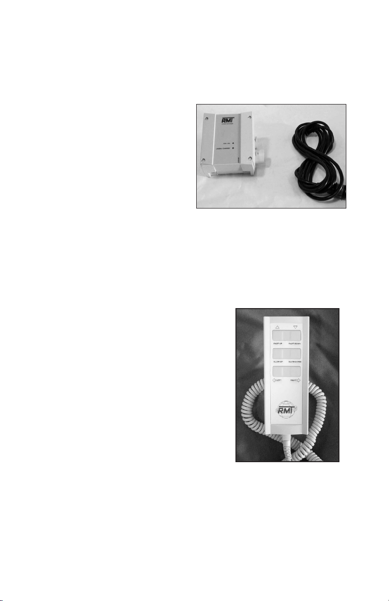
All units perform the following operations:
Rotate the seat. Either left or right in
the direction of the arrows. Splash!
total turning radius is 359º and PAL
total turning radius is 240º.
Raise the seat.
Lower the seat.
Raising and lowering has two speeds,
“fast” and “slow”. Use whichever one
is comfortable.
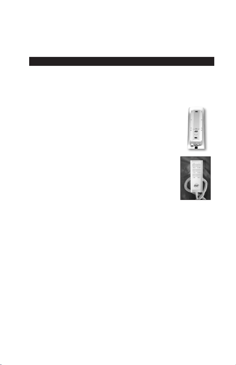
E. BATTERY CHARGING
The rechargeable battery should be placed onto the charging unit when
the lift is not in use. A fully charged battery will provide approximately
30 lifting cycles, depending on the weight of the users. The battery has
no memory, so it is not necessary to
fully discharge the battery prior to
charging. Battery is fully charged
prior to shipping, but should be
checked by looking at LCD indicator
on control unit prior to using to insure
charge level.
Green light indicates connection to
power source. Orange light indicates
battery is charging. When battery is fully charged, orange light will
go off. Set battery on charger in a vertical position to insure good
connection.
F. CONTROL OPERATION
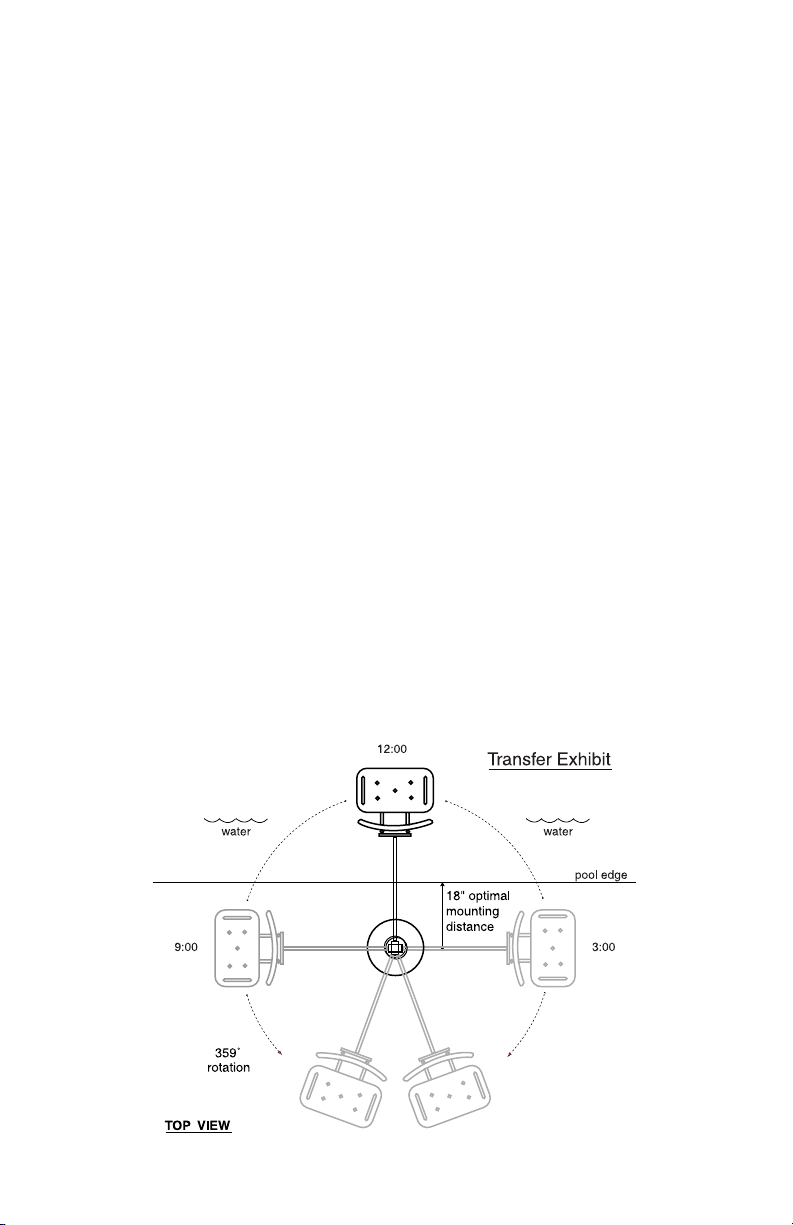
G. TRANSFERRING
(For PAL and Splash! units):
Once the unit is positioned for use, use the following procedure to transfer to
the seat and into the water for desired aquatic activity:
•Rotate the seat to either side of the lift that is the most comfortable
position for transfer. The unit can be rotated to allow plenty of room for
those who may assist with the transfer.
•Raise or Lower the seat to proper transfer height.
•Transfer onto the seat, insuring that the user’s weight is centered on the
seat. If the user is in a wheelchair, keep the wheelchair close by for easy
retrieval.
•Attach seat belt or stability vest, if needed.
•Raise the seat so there is ample legroom for travel.
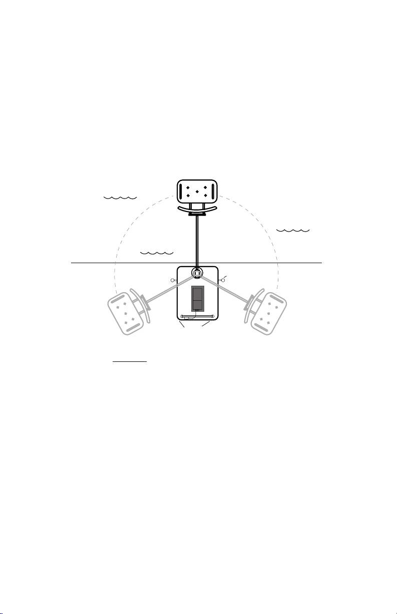
•Rotate seat to the 12:00 position, over the water.
•Lower the seat into the pool. The hand control is submersible, so leave it
connected to the seat while swimming.
•When finished in the pool, return to the seat, insuring that the user’s
weight is centered on the seat.
•Re-Attach seat belt or stability vest, if needed.
•Raise the seat high enough so there is ample legroom for travel.
•Rotate the seat to the original transfer position.
•Raise or Lower the seat to proper transfer height.
•Remove seat belt or vest.
•Transfer off of the seat.
17
Splash!
Transferring Diagram
18
All units are virtually maintenance free. The components should be kept clean.
All surfaces can be wiped down with a spray cleaner. The control box and bat-
tery should be protected from prolonged exposure to water. A small waterproof
cover is provided with each lift to cover the control box when in use. If the lift
is used outdoors, an optional full cover is available and should be considered.
For Splash! Units
Keep the mounting sleeve (anchor) in the pool deck or boat dock free of any
debris that accumulates. This will insure that the lift is seated properly when
installed. An anchor cap is recommended and is available as an optional acces-
sory (see Available Accessories pg. 22)
H. MAINTENANCE
Transferring Note: Positioning For PAL Only
Four things to REMEMBER when positioning PAL for use.
• The PAL is Heavy. It is easy to roll, but DO NOT roll too fast or it may
be hard to stop.
• Position the PAL in an area that allows plenty of room for transferring to
and from a wheelchair.
• Make sure that both of the stabilizing arms are deployed.
• Make sure to engage the locks on the back of the wheels.
TOP VIEW
240ß
rotation
Engage
stabilizers
Lock
brakes!
8:00 4:00
pool edge
12:00
water
water
water
PAL
Transferring Diagram

Unit does not Rotate
Does unit raise or lower?
Yes. Check hand control connection to battery for damaged pins.
– Check connection to 12v motor at battery and at motor.
No.
Is battery charged?
Is battery connected properly?
– Try using another battery
Unit does not Raise or Lower
Does unit rotate?
Yes. Check hand control connection to battery for damaged pins.
– Check connection to actuator at battery and at motor.
No.
Is battery charged?
Is battery connected properly?
– Try using another battery.
I. TROUBLE SHOOTING
If these steps have not corrected your problem,
call us at 800-577-4424.
19
All RehaMed Aquatic Lifting Systems offer a Lifetime Warranty on frame,
excluding powder coated paint finish, which may become scratched with
normal use. All electrical and motor components offer a full One-Year
Warranty. Within the warranty period, we will repair or replace any part
found to be defective upon our examination, but will not pay shipping costs
or other expenses. To obtain warranty service, call or write to us at the
address provided on the inside front cover of this manual. This warranty is
an exclusive remedy and we are not responsible for any consequential or
incidental damages or injury to person or property. This warranty shall not
apply to any product which has been subject to misuse, negligence or
accident, or has been damaged in shipment, or misapplied, or which have
been modified or repaired by unauthorized persons. This warranty only
applies to products owned by persons purchasing directly from the
manufacturer or from our approved distributors or dealers.
J. WARRANTY

Splash!/Hi-Lo/
HD /Mariner PAL/PAL-Hi-Lo
1. Dimensions/Capacity
Overall Height 73 inches 73 inches
Base Dimensions 18 inches Dia. Hgt. 23.5, lgth.37.25,
width 29.25 inches
Total Weight 140 lbs. HD-160 lbs. 845 pounds
Overall Length
(footprint)
70-76” (fully extended) 85-91” (fully extended)
53” in stored position, 66” in stored position
Power 24v DC 24v DC
Battery Life 30 cycles (approx.) 30 cycles (approx.)
Lifting Capacity 300 lbs. HD-375 lbs. 300 pounds
2. Actuator
Lifting: Linak LA32Mechanical Actuator
Max. Thrust: 1680 lb.
Voltage: 24 VDC
Max. Amp: 9
Max. Speed: 0.59 inch/sec.
3. Motor
Rotation: ITT SWMK 403.033
24 VDC 13 RMP
Gearing Ratio: 9:1
4. Battery
Power: Linak Battery Pack BAJ1
24 VDC, IP65
Gel Lead Acid
K. SPECIFICATIONS
20
This manual suits for next models
5
Table of contents


