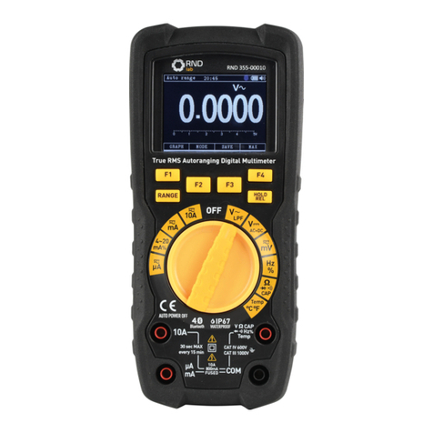
RND lab 355-00010 User manual

www.rnd-electronics.com
True RMS
Autoranging
Digital Multimeter
User Manual
RND 355-00010

3
ENEN
2
Operating instruction for True RMS
Autoranging Digital Multimeter
1. Introducon
• Professional True RMS Industrial Digital Mulmeter and TFT color LCD display,
providing fast A/D converng sampling me, high accuracy , built-in
datalogging and Trend Capture feactures.
• It can trace any interrupted problems of the equipments and watch on
without person.
• It is easy to nd and solve the problems of the producon equipments,
providing Bluetooth technology and memory the datasheets.
• It is much more safe measurements.
• This meter measures AC/DC Voltage & Current, Resistance, Connuity,
Capacitance, Frequency (Electrical & Electronic), Duty Cycle, Diode Test and plus
Thermocouple Temperature.
• It can store and recall data.
• It features a waterproof, rugged design for heavy duty use.
• Proper use and care of this meter will provide many years of reliable service
2. Safety
2-1. Safety Symbols
This symbol adjacent to another symbol, terminal or operang device
indicates that the operator must refer to an explanaon in the
operang instrucons to avoid personal injury or damage to the meter.
WARNING This WARNING
symbol indicates a potenally hazardous situaon, which if not
avoided, could result in death or serious injury.
CAUTION This CAUTION symbol indicates a potenally hazardous situaon, which if not
avoided, may result damage to the product.
MAX This symbol advises the user that the terminal(s) so marked must not be
connect to a circuit point at which the voltage with respect to earth ground
exceeds (in this case) 1000 VAC or VDC.
This symbol adjacent to one or more terminals idenes them as being associat
with ranges that may, in normal use, be subjected to parcularly hazardous
voltages. For maximum safety, the meter and its test leads should not be handled
when these terminals are energized.
Please read this manual before switching the unit on.
Important safety information inside.

4 5
ENEN
This symbol indicates that a device is protected throughout by double insulaon or
reinforced insulaon.
2-2.Per IEC1010 Overvoltage Installaon Category Overvoltage Category I
Equipment of Overvoltage Category I is equipment for connecon to circuits in
which measures
are taken to limit the transient overvoltages to an appropriate low level.
Note: Examples include protected electronic circuits.
Overvoltage Category II
Equipment of Overvoltage Category II is energy-consuming equipment to be supplied
from the
xed installaon.
Note: Examples include household, oce, and laboratory appliances.
Overvoltage Category III
Equipment of Overvoltage Category III is equipment in xed installaons.
Note: Examples include switches in the xed installaon and some equipment for
industrial use with permanent connecon to the xed installaon.
Overvoltage Category IV
Equipment of Overvoltage Category IV is for use at the origin of the installaon.
Note: Examples include electricity meters and primary over-current protecon equipment.
2-3.Safety Instrucons
• This meter has been designed for safe use, but must be operated with cauon.
• The rules listed below must be carefully followed for safe operaon.
1.Never apply voltage or current to the meter that exceeds the specied maximum:
Input Protecon Limits
Funcon
V DC or V AC
mA AC/DC
A AC/DC
Frequency, Resistance, Capacitance,
Duty Cycle, Diode Test, Connuity
Temperature
Surge Protecon: 8kV peak per IEC 61010
Maximum Input
V DC or V AC
800mA 1000V fast acng fuse
10A 1000V fast acng fuse
(10A for 30 seconds max every 10 minutes)
1000VDC/AC rms
1000VDC/AC rms
2.Use extreme CAUTION when working with high voltages.
3.Do not measure voltage if the voltage on the “COM” input jack exceeds 1000V above
earth ground.
4.Never connect the meter leads across a voltage source while the funcon switch
is in the current, resistance, or diode mode, doing so can damage the meter.
5.Always discharge lter capacitors in power supplies and disconnect the power
when making resistance or diode tests.
6.Always turn o the power and disconnect the test leads before opening the covers
to replace the fuse or baeries.
7.Never operate the meter unless the back cover and the baery and fuse covers are in
place and fastened securely.
8.If the equipment is used in a manner not specied by the manufacturer, the
protecon provided by the equipment may be impaired.
3.Descripon
3-1.Meter Descripon
1-50,000 Counts LCD Display
2-F1 Soware Key
3-F2 Soware Key
4-F3 Soware Key
5-F4 Soware Key
6-RANGE Buon
7-HOLD/REL Buon
8-Funcon Switch
9-10A Input Jack
10-μA mA Input Jack
11-Posive Input Jack
12-COM Input Jack
13-Tilt Stand
14-Baery Cover
OFF
Ω
CAP
mA
^rqO POWER OFF
10A
mA
A
10A V
10A
800mA
FUSED COM
CAT IV 600V
CAT III 1000V
True RMS Autoranging Digital Multimeter
30 sec MAX
every 15 min
IP67
t^TERPROOF
V
V CAPΩ
Hz
%
Temp
µA
AC+DC
Hz
%
Temp
°C °F
LP F
mA%
4~20 mV
_äìÉíççí Ü
RANGE HOLD
REL
F1
F2
F4
F3
1
2
6
4
5
7
8
9
10
11
12
3
13
14

6 7
ENEN
3-2.Understanding the Display
1.So key labels Indicates the funcon of the buon just below the displayed label.
2.Bar graph Analog display of the input signal.
3.Minus sign Indicates a negave reading.
4.Displays measurement informaon about the input signal.
5.Indicates the range the Meter is in and the ranging mode (auto or manual)
6.Time Indicates the me set in the internal clock.
7.Buetooth Indicate
8.Baery level Indicates the charge level baeries.
9.Beeper Indicates the Meter’s beeper is enabled (not associated with the
connuity beeper).
10.Units Indicates the units of measure.
-0.0 4
Auto range 06:32
GRAPH
-500 -300 -100 01 00 300 500mV
MODE SAVE MAX
mV
1
2
4
5 6 7
10
9
8
3
3-3.Understanding the Push Buons
The 6 push buons on the front of the Meter acvate features that augment the funcon
selected using the rotary switch, navigate menus or control power to Meter circuits.
F1 Soware Key: Default switch to Graph measure.
F2 Soware Key: Default modes related to the rotary switch funcon
F3 Soware Key: Default into save mode default Display. And wake up for APO.
F4 Soware Key: Default modes MIN/MAX starts and stops MIN/MAX recording.
RANGE Buon: Into manual range and select range of the measure, if pressing the Range
Buon for greater that 1 second will return Auto Range.
HOLD/REL Buon: Freezes the present reading in the display and allows the
display to be saved,
if pressing the HOLD/REL Buon for greater that 1 second will switch relave mode.
HOLD/REL Buon: Freezes the present reading in the display and allows the display to be
saved,if pressing the HOLD/REL Buon for greater that 1 second will switch relave mode.
3-4.Understanding the Rotary Switch
• Select a primary measurement funcon by posioning the rotary switch to one of the
icons around its perimeter.
• For each funcon, the Meter presents a standard display for that funcon
(range, measurement units and modiers).
• Buon choices made in one funcon do not carry over into another funcon.
AC/DC Amps Measurements.
mA : AC/DC Milliamps Measurements.
% 4-20mA Measurements.
AC/DC Microampere Measurements up to 5,000μA.
AC Voltage Measurements
DC and AC+DC Voltage Measurements.
AC/DC Milli-Volts Measurements.
Frequency and Duty Cycle Measurements.
Ω Resistance, Diode Test, Capacitance and Connuity Measurements.
Temperature Measurements.
10A :
mA :
4~20mA%:
µA :
V :
V AC+DC:
mV :
Hz%:
CAP:
Temp:

8 9
EN EN
3-5.Using the Input Terminals
• All funcons except current use the V/OHMS and COM input terminals.
• The two current input termin for 500mA and 10A current measurement.
10A: Input for 0A to 10.00A current (20A overload for 30 seconds on, 10 minutes o).
μAmA: Input for 0A to 500mA current measurements.
COM: Return terminal for all measurements.
VΩCAP Hz Temp: Input for Voltage, Connuity, Resistance, Diode Test, Conductance,
Capacitance.
4.Measure Funcon
4-1.AC Voltage Measurement
WARNING: Risk of Electrocuon. The probe ps may not be long enough to contact the live
parts inside some 240V outlets for appliances because the contacts are recessed deep in the
outlets. As a result, the reading may show 0 volts when the outlet actually has voltage on it.
Make sure the probe ps are touching the metal contacts inside the outlet before assuming
that no voltage is present.
CAUTION: Do not measure AC voltages if a motor on the circuit is being switched ON or OFF.
Large voltage surges may occur that can damage the meter.
1. Set the funcon switch to the VAC Posion.
2. Insert the black test lead into the COM Input Jack and the red test lead into the Posive
Input Jacks.
3. Posion the black test probe p and red test probe p respecvely in the spots of the
circuit to be measured.
4. Read the AC voltage in the display.
OFF
CAP
mA
AUTO POWER OFF
10A
mA
A
10A V
10A
800mA
FUSED COM
CAT IV 600V
CAT III 1000V
True RMS Autoranging Digital Multimeter
30 sec MAX
every 15 min
IP67
WATERPROOF
V
V CAP
Hz
%
Temp
µA
AC+DC
Hz
%
Temp
°C °F
LPF
mA%
4~20 mV
Bluetooth
RANGE HOLD
REL
F1
F2
F4
F3
5. 0000
Auto range 06:32
GRAPH
01 23 4 5V
MODE SAVE MAX
V
4-2.DC Voltage Measurement
CAUTION: Do not measure DC voltages if a motor on the circuit is being switched ON or
OFF. Largevoltage surges may occur that can damage the meter.
1. Set the funcon switch to the VDC AC+DC Posion.
2. Insert the black test lead into the COM Input Jack and the red test lead into the
Posive Input Jacks.
3. Posion the black test probe p and red test probe p respecvely in the spots of the
circuit to be measured.
4. Read the DC voltage in the display.
OFF
CAP
mA
AUTO POWER OFF
10A
mA
A
10A V
10A
800mA
FUSED COM
CAT IV 600V
CAT III 1000V
True RMS Autoranging Digital Multimeter
30 sec MAX
every 15 min
IP67
WATERPROOF
V
V CAP
Hz
%
Temp
µA
AC+DC
Hz
%
Temp
°C °F
LPF
mA%
4~20 mV
Bluetooth
RANGE HOLD
REL
F1
F2
F4
F3
5. 0000
Auto range 06:32
GRAPH
-5 5V
MODE SAVE MAX
V
-4 -3 -2 -1 01 23 4

10 11
EN EN
4-3.AC+DC Voltage Measurement
1. Set the funcon switch to the VDC AC+DC Posion.
2. Insert the black test lead into the COM Input Jack and the red test lead into the Posive
Input Jacks.
3. Press the MODE Buon (F2) to indicate “AC+DC” on the display.
4. Posion the black test probe p and red test probe p respecvely in the spots of the
circuit to be measured.
5. Read the AC+DC voltage in the display.
OFF
CAP
mA
AUTO POWER OFF
10A
mA
A
10A V
10A
800mA
FUSED COM
CAT IV 600V
CAT III 1000V
True RMS Autoranging Digital Multimeter
30 sec MAX
every 15 min
IP67
WATERPROOF
V
V CAP
Hz
%
Temp
µA
AC+DC
Hz
%
Temp
°C °F
LPF
mA%
4~20 mV
Bluetooth
RANGE HOLD
REL
F1
F2
F4
F3
5. 0000
Auto range 06:32
GRAPH MODE SAVE MAX
V
AC+DC
0. 0000 V
5. 0000 V
4-4.mV Voltage Measurement
CAUTION: Do not measure mV voltages if a motor on the circuit is being switched ON or
OFF. Large voltage surges may occur that can damage the meter.
1. Set the funcon switch to the mVAC/DC Posion.
2. Insert the black test lead into the COM Input Jack and the red test lead into the Posive
Input Jacks.
3. Press the MODE Buon (F2) to indicate “AC” or “DC” on the display.
4. Posion the black test probe p and red test probe p respecvely in the spots of the
circuit to be measured.
5. Read the mV voltage in the display.
500. 00
Auto range 06:32
GRAPH
-500 -300 -100 01 00 300 500mV
MODE SAVE MAX
mV
OFF
CAP
mA
AUTO POWER OFF
10A
mA
A
10A V
10A
800mA
FUSED COM
CAT IV 600V
CAT III 1000V
True RMS Autoranging Digital Multimeter
30 sec MAX
every 15 min
IP67
WATERPROOF
V
V CAP
Hz
%
Temp
µA
AC+DC
Hz
%
Temp
°C °F
LPF
mA%
4~20 mV
Bluetooth
RANGE HOLD
REL
F1
F2
F4
F3
4-5.DC Current Measurement
CAUTION: Do not make 10A current measurements for longer than 30 seconds, Exceeding
30
seconds may cause damage to the meter and/or the test leads.
1. Insert the black test lead banana plug into the COM Input Jack.
2. For current measurements up to 5000μA DC, set the funcon switch to the μA AC/DC
Posion and insert the red test lead banana plug into the μA/mA Input Jack.
3. For current measurements up to 500mA DC, set the funcon switch to the mA AC/DC
Posion and insert the red test lead banana plug into the μA/mA Input Jack.
4. For current measurements up to 10A DC, set the funcon switch to the 10A AC/DC
Posion and insert the red test lead banana plug into the 10A Input Jack.
5. Press the MODE Buon (F2) to indicate “DC” on the display.
6. Remove power from the circuit under test, then open up the circuit at the point where
you wish to measure current.
7. Touch the black test probe p to the negave side of the circuit; Touch the red test probe
p to the posive side of the circuit.
8. Apply power to the circuit.
9. Read the current in the display.

12 13
EN EN
OFF
CAP
mA
AUTO POWER OFF
10A
mA
A
10A V
10A
800mA
FUSED COM
CAT IV 600V
CAT III 1000V
True RMS Autoranging Digital Multimeter
30 sec MAX
every 15 min
IP67
WATERPROOF
V
V CAP
Hz
%
Temp
µA
AC+DC
Hz
%
Temp
°C °F
LPF
mA%
4~20 mV
Bluetooth
RANGE HOLD
REL
F1
F2
F4
F3
500. 00
Auto range 06:32
GRAPH
-500 -300 -100 01 00 300 500µA
MODE SAVE MAX
µA
4-6.AC Current Measurement
CAUTION: Do not make 10A current measurements for longer than 30 seconds, Exceeding
30 seconds may cause damage to the meter and/or the test leads.
1. Insert the black test lead banana plug into the COM Input Jack.
2. For current measurements up to 5000μA AC, set the funcon switch to the μA AC/DC
Posion and insert the red test lead banana plug into the μA/mA Input Jack.
3. For current measurements up to 500mA AC, set the funcon switch to the mA AC/DC
Posion and insert the red test lead banana plug into the μA/mA Input Jack.
4. For current measurements up to 10A AC, set the funcon switch to the 10A AC/DC
Posion and insert the red test lead banana plug into the 10A Input Jack.
5. Press the MODE Buon (F2) to indicate “AC” on the display.
6. Remove power from the circuit under test, then open up the circuit at the point where
you wish to measure current.
7. Touch the black test probe p to the negave side of the circuit; Touch the red test probe
p to the posive side of the circuit.
8. Apply power to the circuit.
9. Read the current in the display.
OFF
CAP
mA
AUTO POWER OFF
10A
mA
A
10A V
10A
800mA
FUSED COM
CAT IV 600V
CAT III 1000V
True RMS Autoranging Digital Multimeter
30 sec MAX
every 15 min
IP67
WATERPROOF
V
V CAP
Hz
%
Temp
µA
AC+DC
Hz
%
Temp
°C °F
LPF
mA%
4~20 mV
Bluetooth
RANGE HOLD
REL
F1
F2
F4
F3
500. 00
Auto range 06:32
GRAPH
-500 -300 -100 01 00 300 500µA
MODE SAVE MAX
µA
4-7.% 4~20mA Measurement
1. Set up and connect as described for DC mA measurements.
2. Set the funcon switch to the 4~20mA% Posion.
3. The meter will display loop current as a % with 0mA=-25%, 4mA=0%, 20mA=100%
and 24mA=125%.
OFF
CAP
mA
AUTO POWER OFF
10A
mA
A
10A V
10A
800mA
FUSED COM
CAT IV 600V
CAT III 1000V
True RMS Autoranging Digital Multimeter
30 sec MAX
every 15 min
IP67
WATERPROOF
V
V CAP
Hz
%
Temp
µA
AC+DC
Hz
%
Temp
°C °F
LPF
mA%
4~20 mV
Bluetooth
RANGE HOLD
REL
F1
F2
F4
F3
25. 00
Auto range 06:32
MODE SAVE MAX
%

14 15
EN EN
4-8.Frequency/Duty Cycle(%) Measurement
1. Set the funcon switch to the Hz% Posion.
2. Insert the black test lead into the COM Input Jack and the red test lead into the Posive
Input Jacks.
4. Posion the black test probe p and red test probe p respecvely in the spots of the
circuit to be measured.
5. Read the Frequency in the display.
6. Press the MODE Buon (F2) again to indicate “%” on the display.
7. Read the % of duty cycle on the display.
OFF
CAP
mA
AUTO POWER OFF
10A
mA
A
10A V
10A
800mA
FUSED COM
CAT IV 600V
CAT III 1000V
True RMS Autoranging Digital Multimeter
30 sec MAX
every 15 min
IP67
WATERPROOF
V
V CAP
Hz
%
Temp
µA
AC+DC
Hz
%
Temp
°C °F
LPF
mA%
4~20 mV
Bluetooth
RANGE HOLD
REL
F1
F2
F4
F3
50. 000
Auto range 06:32
MODE SAVE MAX
Hz
4-9.Resistance Measurement
WARNING: To avoid electric shock, disconnect power to the unit under test and discharge
all capacitors before taking any resistance measurements, Remove the baeries and unplug
the line cords.
1. Set the funcon switch to the Ω CAP Posion.
2 .Insert the black test lead into the COM Input Jack and the red test lead into the Posive
Input Jacks.
4. Posion the black test probe p and red test probe p respecvely in the spots of the
circuit to be measured.
5. Read the Resistance in the display.
4-10.Connuity Check
WARNING: To avoid electric shock, disconnect power to the unit under test and discharge
all capacitors before taking any capacitance measurements. Remove the baeries and
unplug the line cords.
1. Set the funcon switch to the Ω CAP Posion.
2. Insert the black test lead into the COM Input Jack and the red test lead into the Posive
Input Jacks.
4. Press the MODE Buon (F2) again to indicate “Ω” and “ ” on the display.
5. Posion the black test probe p and red test probe p respecvely in the spots of the
circuit to be measured.
6. If the resistance is less than approximately 25Ω, the audible signal will sound. If the circuit
is open, the display will indicate “OL”.
50. 000
Auto range 06:32
GRAPH
01 02 03 0 40 50M
MODE SAVE MAX
M
OFF
CAP
mA
AUTO POWER OFF
10A
mA
A
10A V
10A
800mA
FUSED COM
CAT IV 600V
CAT III 1000V
True RMS Autoranging Digital Multimeter
30 sec MAX
every 15 min
IP67
WATERPROOF
V
V CAP
Hz
%
Temp
µA
AC+DC
Hz
%
Temp
°C °F
LPF
mA%
4~20 mV
Bluetooth
RANGE HOLD
REL
F1
F2
F4
F3

16 17
EN EN
25. 000
Auto range 06:32
01 00 2003 00 400 500
MODE SAVE MAX
OFF
CAP
mA
AUTO POWER OFF
10A
mA
A
10A V
10A
800mA
FUSED COM
CAT IV 600V
CAT III 1000V
True RMS Autoranging Digital Multimeter
30 sec MAX
every 15 min
IP67
WATERPROOF
V
V CAP
Hz
%
Temp
µA
AC+DC
Hz
%
Temp
°C °F
LPF
mA%
4~20 mV
Bluetooth
RANGE HOLD
REL
F1
F2
F4
F3
4-11.Diode Test
1. Set the funcon switch to the Ω CAP Posion.
2.Insert the black test lead into the COM Input Jack and the red test lead into the Posive
Input
Jacks.
4.Press the MODE Buon (F2) again to indicate “V” and “ ” on the display.
5.Forward voltage will typically indicate 0.400 to 3.200V, Reverse voltage will indicate “OL”;
Shorted devices will indicate near 0V and an open device will indicate “OL” in
both polaries.
0. 5000
Auto range 06:32
01 23 4 5V
MODE SAVE MAX
OFF
CAP
mA
AUTO POWER OFF
10A
mA
A
10A V
10A
800mA
FUSED COM
CAT IV 600V
CAT III 1000V
True RMS Autoranging Digital Multimeter
30 sec MAX
every 15 min
IP67
WATERPROOF
V
V CAP
Hz
%
Temp
µA
AC+DC
Hz
%
Temp
°C °F
LPF
mA%
4~20 mV
Bluetooth
RANGE HOLD
REL
F1
F2
F4
F3
V
4-12.Capacitance Measurement
WARNING: To avoid electric shock, disconnect power to the unit under test and discharge all
capacitors before taking any capacitance measurements. Remove the baeries and unplug the line
cords.
1. Set the funcon switch to the Ω CAP Posion.
2.Insert the black test lead into the COM Input Jack and the red test lead into the Posive Input
Jacks.
3.Press the MODE Buon (F2) again to indicate “nF” on the display.
4. Posion the black test probe p and red test probe p respecvely in the spots of the circuit to
be measured.
5. Read the Capacitance in the display.
OFF
CAP
mA
AUTO POWER OFF
10A
mA
A
10A V
10A
800mA
FUSED COM
CAT IV 600V
CAT III 1000V
True RMS Autoranging Digital Multimeter
30 sec MAX
every 15 min
IP67
WATERPROOF
V
V CAP
Hz
%
Temp
µA
AC+DC
Hz
%
Temp
°C °F
LPF
mA%
4~20 mV
Bluetooth
RANGE HOLD
REL
F1
F2
F4
F3
50. 00
Auto range 06:32
nF
MODE SAVE MAX

18 19
EN EN
OFF
CAP
mA
AUTO POWER OFF
10A
mA
A
10A V
10A
800mA
FUSED COM
CAT IV 600V
CAT III 1000V
True RMS Autoranging Digital Multimeter
30 sec MAX
every 15 min
IP67
WATERPROOF
V
V CAP
Hz
%
Temp
µA
AC+DC
Hz
%
Temp
°C °F
LPF
mA%
4~20 mV
Bluetooth
RANGE HOLD
REL
F1
F2
F4
F3
250. 0
Auto range 06:32
°C
MODE SAVE MAX
4-13.Temperature Measurement
1. Set the funcon switch to the Temp Posion.
2. Insert the Temperature Probe into the input jacks, making sure to observe the
correct polarity.
3. Press the MODE Buon (F2) to indicate °C or °F.
4. Touch the Temperature Probe head to the part whose temperature you wish to measure,
Keep the probe touching the part under test unl the reading stabilizes
(About 30 seconds).
5. Read the temperature in the display.
0. 0000
Auto range 06:32
GRAPH
01 23 4 5V
MODE SAVE MAX
V
Auto range 06:32
START FASTS LOWC ANCEL
0
0.0000 V
Rate: 0.2 s
Range: 0.01
5.Default Display
5-1.Graph Measure
• Press the GRAPH Buon (F1), Meter will switch to Graph measure.
• Press the START Buon (F1).
• Press the FAST Buon (F2) or the SLOW Buon (F3) to adjust sampling rate.
• Press the CANCEL Buon (F1) to exit Graph and return to normal measurement mode.
Press the STOP Buon (F4).
START FAST SLOW CANCEL

20 21
EN EN
• Press the SAVE Buon (F1) to save graph.
• Press the BACK Buon (F4) to return.
5-2.Capturing Minimum and Maximum Values
• To acvate the MAX/MIN mode, Press MAX Buon (F4) at measure mode.
• As shown in Figure, the Meter displays eat the top of the measurement page, and the
MAX/MIN start date and me along the boom of the page.
• In addion, the recorded maximum, average, and minimum values appear in the
secondary display with their respecve elapsed mes.
• To stop a MAX/MIN recording session, press the STOP Buon (F2).
• Thesummary informaon in the display freezes, and the sokeys change funcon to allow
saving the collected data.
• Pressing the CLOSE Buon (F4) exits the MAX/MIN record session without saving the
collected data.
• To save the MAX/MIN screen data, the MAX/MIN session must be ended by pressing the
STOP Buon (F2), Next, press the SAVE Buon (F3).
Auto range 06:32
SAVE BACK
0
0.0000 V
Rate: 0.2 s
Range: 0.01
5-3.Capturing Peak Values
To acvate the peak mode, at AC measure MAX/MIN mode , Press the PMAX Buon (F4).
5-4.Relave Values
To acvate the relave mode, Press the HOLD/REL Buon for greater that 1 second.
-0 . 0430
Auto range 06:32
GRAPH MODE SAVE MAX
V
REL
Reference0 .3079 V
0.2649 V
5-5.Hold Mode
• To freeze the display for any funcon, Press the HOLD/REL Buon.
• Press the SAVE Buon (F3) to memory and the CLOSE Buon (F4) return measure.
STOP

22 23
EN EN
5-6.Save Funcon
Press the SAVE Buon (F3), into save menu.
Auto range 06:32
ENTER UP DOWN CANCEL
5-7.Storing Individual Measurement Data
• For common measurement funcons, a snapshot of the screen data is saved by pressing
the SAVE Buon (F3).
• Then pressing the DOWN Buon (F3) to the save select item, pressing the
ENTER Buon (F1).
5-8.Viewing Memory Data
• Viewing data stored in the Meter’s memory is performed through the save menu.
• Press the DOWN Buon (F3), posion the menu selector next to the menu item labeled
ViewM, and pressing the ENTER Buon (F1).
Auto range 06:32
ENTER UP DOWN CANCEL
5-9.Viewing Graph Data
• Viewing data stored in the Meter’s memory is performed through the save menu.
• Press the DOWN Buon (F3), posion the menu selector next to the menu item labeled
ViewG, and pressing the ENTER Buon (F1).
• Press the << Buon (F2) and the >> Buon (F3) to move cursor.
5-10.Recording Measurement Data
• Press the SAVE Buon (F3), then pressing the DOWN Buon (F3) to the Record select
Item, pressing the ENTER Buon (F1), Press the sokey labeled Start to start records.
• The recording session will connue unl the allocated memory is used, the baeries
expire, the rotary switch is moved, or the session is terminated by pressing the CLOSE
Buon (F4) labeled stop.
Auto range 06:32
ENTER UP DOWN CANCEL
366. 55
Auto range 06:32
DOWN CLOSE
mV
UPENTER
Set Duration: 00Days 00Hrs 01Min
Set Sample Interval: 00Min 01Sec
Start Record
Battery: partly empty
ENTER UP DOWN CANCEL
DOWN
Set Duraon: 00Days 00Hrs 01Mins
Set Sample Interval: 00Min 01Sec
Start Record
Baery: partly empty
DOWN DOWN

24 25
EN EN
5-12.Info
• Viewing data stored in the Meter’s memory is performed through the save menu.
• Press the DOWN Buon (F3), posion the menu selector next to the menu item labeled
Info and pressing the the ENTER Buon (F1).
Auto range 06:32
ENTER UP DOWN CANCEL
Auto range 06:32
DOWN CLOSEUP
g
r
6.Setup Opons
• Viewing data stored in the Meter’s memory is performed through the save menu.
• Press the DOWN Buon (F3), posion the menu selector next to the menu item label
Setup and pressing the ENTER Buon (F1).
Auto range 06:32
ENTER UP DOWN CANCEL
Auto range 06:32
ENTER UP DOWN CANCEL
Reset
Format
Display
Meter Inf
Bluetooth
Calibration
Temperature
6-1.Reseng Meter
• The Meter’s setup opons can be reset to default values through the setup menu.
• Open the setup menu, posion the menu selector next to the menu item labeled Reset
and press the ENTER Buon (F1).
• Then a message will appear asking to conrm the reset acon.
• Press the OK Buon (F2) to perform the reset.
6-2.Meter Info
• The Meter Info selecon lists the serial number, rmware version, are displayed.
• Open the setup menu, posion the menu selector next to the menu item labeled Meter
Info and press the ENTER Buon (F1).
DOWN DOWN
Fno. Graph- According to graphically display
measurement informaon
Fno. Mode-Related to the rotary switch funcon
Fno. Save-Accesses the memory management
menu for saving measuremnt, seng up recording
sessions, or viewing and deleng stored
measurements from memory
CLOSE
DOWN DOWN
5-11.Viewing Trend Data
• Viewing data stored in the Meter’s memory is performed through the save menu.
• Press the DOWN Buon (F3), Posion the menu selector next to the menu item labeled
ViewR and pressing the ENTER Buon (F1).
• Press the the TREND Buon (F1).
• Press the + Buon (F2) to increase graph resoluon, press the >> Buon (F3) to
move cursor.

26 27
EN EN
Auto range 06:32
ENTER UP DOWN CANCEL
Reset
Format
Display
Meter Inf
Bluetooth
Calibration
Temperature
Auto range 06:32
CLOSE
6-3.Seng Format
• Open the setup menu, posion the menu selector next to the menu item labeled Format
and press the ENTER Buon (F1).
• Using the cursor buons, move the menu selector next to the menu item labeled
Numeric(Date\Time) format, press the EDIT Buon (F1) to edit, select 0.0000(0,0000) and
MM/DD/YY(DD/MM/YY) and 24 HOUR(12 HOUR) format.
Auto range 06:32
ENTER UP DOWN CANCEL
Reset
Format
Display
Meter Info
Bluetooth
Calibration
Temperature
Auto range 06:32
CLOSE
Format
DOWNUPEDIT
Beeper
Numeric Format
Date Format
Time Format
Auto range 06:32
CANCEL
Format
Beeper
Numeric Format
Date Format
Time Format
6-4.Seng Display
• Open the setup menu.
• Posion the menu selector next to the menu item labeled Display and press the ENTER
Buon (F1).
O
Meter Info
Fireware Version: V1.10
DOWN
DOWN
DOWN MM/DD/YY MM/DD/YY
6-5.Seng Date and Time
• Open the setup menu, posion the menu selector next to the menu item labeled Display
and press the ENTER Buon (F1).
• Next posion the menu selector next to either the Set Date item or Set Time item and
press the EDIT Buon (F1).

28 29
EN EN
6-6.Auto Power O
• Open the setup menu, posion the menu selector next to the menu item labeled Display
and press the ENTER Buon (F1).
• Then Posion the menu selector next to the menu item labeled Auto Power O and press
the EDIT Buon (F1).
• To set Auto Power O, use UP (F2) and DOWN (F3) to adjust the me to one of
the preset values.
• 0 is disable the meout feature.
• Press the OK Buon (F1) to set the selected me, press the CANCEL Buon (F4) to return.
6-7.Foreground and Background
• Open the setup menu, posion the menu selector next to the menu item labeled Display
and press the ENTER Buon (F1).
• Then posion the menu selector next to the menu item labeled Foreground and
Background and press the OK Buon (F1).
• Use UP (F2) and DOWN (F3) to adjust.
6-8.Set Font
• Open the setup menu, posion the menu selector next to the menu item labeled Display
and press the ENTER Buon (F1).
• Then Posion the menu selector next to the menu item labeled Select Font and press the
EDIT Buon (F1)
• Use UP (F2) and DOWN (F3) to adjust.
Auto range 06:32
ENTER UP DOWN CANCEL
Reset
Format
Display
Meter Info
Bluetooth
Calibration
Temperature
Auto range 06:32
CANCELOK
Turn on Bluetooth?
6-9.Bluetooth
•You can use the Bluetooth communication link and transfer the contents of a meter’s
memory to a PC.
• Open the setup menu, position the menu selector next to the menu item labeled
Bluetooth and press the the ENTER Button (F1).
• Turn on Bluetooth” and press the OK Button (F1) , “Turn off Bluetooth” and press the OK
Button (F1).
•The Bluetooth app can be installed on mobile phones. The recommended
communication distance between mobile device and multimeter should not exceed
5.5m, and it will need to be re-connected manually if disconnected.

30 31
EN EN
7.Replacing the Baeries
WARNING: To avoid electric shock, disconnect the test leads from any source of voltage
before removing the baery cover.
WARNING: To avoid electric shock, do not operate the meter unl the baery cover is in
place and fastened securely.
Refer to Figure and replace the baeries as follows:
1. Turn the Meter o and remove the test leads from the terminals.
2. Remove the baery door assembly by using a standard blade screwdriver to turn
the baery door screw one-half turn counterclockwise.
3. Replace the baeries with 7.4 volt charge baeries Observe proper polarity.
4. Reinstall the baery door assembly and secure it by turning the screw one-half
turn clockwise.
8.Replacing the Fuses
WARNING: To avoid electric shock, disconnect the test leads from any source of voltage
before removing the meter cover.
WARNING: To avoid electric shock, do not operate your meter unl the fuse cover is in place
and fastened securely.
Referring to Figure, examine or replace the Meter’s fuses as follows:
1. Turn the Meter o and remove the test leads from the terminals.
2. Remove the baery door assembly by using a standard blade screwdriver to turn
the baery door screw one-half turn counterclockwise.
3. Remove the fuse by gently prying one end loose, then sliding the fuse out of its bracket.
4. Install only specied replacement fuses.
5. Reinstall the baery door assembly and secure it by turning the screw one-half
turn clockwise.
6. Remove the six screws securing the rear cover.
7. Gently remove the old fuse and install the new fuse into the holder.
8. Replace and secure the rear cover, baery and baery cover.

32 33
EN EN
9. Li-ion Baery Charge
1. Turn the Meter o and remove the test leads from the terminals.
2. Remove the baery door assembly by using a standard blade screwdriver to turn
the baery door.
3. Install the baery to the external charging stand, plug in the special adapter and
plug the adapter into a live socket. (Specic charging instrucons are shown in the
charging stand instrucons).
10.Specicaons
10-1.Specicaons
500mV
5V
50V
500V
1000V
0.01mV
0.0001V
0.001V
0.01V
0.1V
±(0.5% +
5 digits)
50/60Hz <1kHz
±(3.0% +
5 digits)
±(1.5% +
10 digits)
<5kHz
±(3.0% +
5 digits)
<20kHz (1)
±(5.5% +
20 digits)
±(3.5% +
10 digits)
Unspecied
Unspecied Unspecied
500mV (2)
5V
50V
500V
1000V
0.01mV
0.0001V
0.001V
0.01V
0.1V
±(0.1% + 5 digits)
±(0.05% + 5 digits)
±(0.1% + 5 digits)
(2): When using the relave mode (REL Q) to compensate for osets.
(1): Upper 10 % of range.
5V
50V
500V
1000V
0.0001V
0.001V
0.01V
0.1V
<1kHz
±(1.2% + 20 digits)
<5kHz
±(3.5% + 20 digits)
Unspecied
500 Ω (3)
5K Ω (3)
50KΩ (3)
500K Ω (3)
5M Ω (3)
50M Ω (3)
0.01(3)
0.0001(3)
0.001k(3)
0.1k(3)
0.0001M(3)
0.001M(3)
±(0.20% + 10 digits)
±(0.20% + 5 digits)
±(0.50% + 5 digits)
±(2.0% + 20 digits)
(3): When using the relave mode (REL Q) to compensate for osets.
500μA
5000μA
50mA
500mA
10A
0.01μA
0.1μA
0.001mA
0.01mA
0.001A
±(0.5% + 5 digits)
±(0.3% + 8 digits)
±(0.5% + 8 digits)

34 35
EN EN
500μA
5000μA
50mA
500mA
10A
0.01μA
0.1μA
0.001mA
0.01mA
0.001A
50/60Hz
±(0.8% + 5 digits)
<5kHz
±(3% + 5 digits)
10A: 30 sec max with reduced accuracy.
All AC current ranges are specied from 5% of range to 100% of range.
5nF (3) 0.001nF
50nF 0.01nF
500nF 0.1nF
5μF 0.001μF
50μF 0.01μF
500μF 0.1μF
10mF 0.01mF
±(1.5% + 20 digits)
±(1.5% + 8 digits)
±(1.0% + 8 digits)
±(1.5% + 15 digits)
±(1.0% + 8 digits)
±(1.5% + 8 digits)
±(2.5% + 20 digits)
(3): With a lm capacitor or beer, using relave mode (REL ) to zero residual.
50Hz
500Hz
5kHz
50kHz
500kHz
5MHz
10MHz
0.001Hz
0.01Hz
0.0001kHz
0.001kHz
0.01kHz
0.0001MHz
0.001MHz
±(0.01% + 5 digits)
Unspecied
Sensivity: 2V rms min. at 20% to 80% duty cycle and <100kHz; 5Vrms min at 20% to 80% duty
cycle and >100kHz.
10.00-10kHz 0.01-0.001kHz ±(0.5% reading)
Sensivity: 2Vrms.
0.1 to 99.90% 0.01% ±(1.2% + 5 digits)
Pulse width: 100μs-100ms, Frequency: 5Hz to 150kHz.
-200 to 1350°C
-328 to 2462°F
0.1°C
0.1°F
±(1.0% + 3.0°C)
±(1.0% + 5.4°C)
Does not include error of the thermocouple probe.
Accuracy specicaon assumes ambient temperature stable to ±1°C.
Use a long me, reading will increase 2°C.
<-50°C Temp Rang accuracy ±(3%+5°C).
10-2.General Specicaons
Enclosures Double molded
Shock 6.5 feet (2 meters)
Waterproof IP67
Diode Test Test current of 1.5mA maximum, open circuit voltage 3.2V
DC typical.
Connuity Check Audible signal will sound if the resistance is less than 25Ω(ap
prox.), test current <0.35mA.
PEAK Captures peaks >1ms
Temperature Sensor Requires type K thermocouple
Input Impendance >10MΩ VDC & >9MΩ VAC
AC Response True rms
AC Response The term stands for “Root-Mean-Square,” which represents the
method of calculaon of the voltage or current value.
Average responding mulmeters are calibrated to read correctly
only on sine waves and they will read inaccurately on non-sine
wave or distorted signals. True rms meters read accurately
on either type of signal.
ACV Bandwidth 50Hz to 20000Hz
Display 50,000 Counts TFT LCD
Overrange Indicaon “OL” is displayed
Auto Power O 5-30minutes (approximately) with disable feature
Polarity Automac (no indicaon for posive); Minus (-) sign for negave
Measurement Rate 20 mes per second, nominal
Low Baery Indicaon “ ” is displayed if baery voltage drops below operang voltage
Baery One 7.4 volt (NEDA 1604) baery
Fuses mA/μA ranges: 0.8A/1000V ceramic fast blow A range; 10A/1000V
ceramic fast blow.

36
37
EN
DE
Operang Temperature 5 to 40°C (41 to 104°F)
Storage Temperature -20 to 60°C (-4 to 140°F)
Operang Humidity Max 80% up to 31°C (87°F) decreasing linearly to 50% at
40°C (104°F)
Storage Humidity 50% at 40°C (104°F)
Operang Altude <80% 7000. (2000meters) maximum.
This meter is intended for origin of installaon use and
protected, against the users, by double insulaon per
EN61010-1 and IEC61010-1 2nd Edion (2001) to Category
IV 600V and Category III 1000V; Polluon Degree 2. The
meter also meets UL 61010-1, 2nd Edion (2004), CAN/CSA
C22.2 No. 61010-1 2nd Edion (2004), and UL 61010-2-033,
1st Edion (2012).
www.rnd-electronics.com
True RMS-Digitalmultimeter
mit automatischer
Bereichswahl
Benutzerhandbuch
RND 355-00010
38
39
DE
DE
Bedienungsanleitung für das True
RMS-Digitalmultimeter mit automatischer
Bereichswahl
1. Einleitung
• Professionelles True RMS-Digitalmulmeter für Industrieanwendungen und
TFT-LCD-Farbdisplay für schnelle A/D-Umwandlung, hohe Präzision, integrierte
Datenprotokollierung und Funkonen zur Trendaufzeichnung.
• Es kann alle Störungen durch Unterbrechung in den Geräten aufspüren und ohne Einsatz
von Personal weiterverfolgen.
• Die Probleme der Produkonsausrüstung können dank Bluetooth-Technologie und
Speicherung der Datenbläer einfach aufgespürt und gelöst werden.
• Die Messungen bieten erheblich mehr Sicherheit.
• Dieses Messgerät misst AC/DC-Spannung und -Strom, Widerstand, Durchgang, Kapazität,
Frequenz (elektrisch und elektronisch), Tastverhältnis, Diodentest und zusätzlich die
Temperatur des Thermoelements.
• Es können Daten gespeichert und abgerufen werden.
• Es verfügt über ein wasserdichtes, robustes Design für hohe Beanspruchung.
• Bei ordnungsgemässer Verwendung und Pege dieses Messgeräts arbeitet es viele Jahre
zuverlässig
2. Sicherheit
2-1. Sicherheitssymbole
Dieses Symbol neben einem anderen Symbol, einer Klemme oder einem Bediengerät
weist darauf hin, dass der Bediener eine Erläuterung in der Bedienungsanleitung
beachten muss, um Verletzungen oder Schäden am Messgerät zu vermeiden.
WARNUNG Dieses Symbol WARNUNG weist auf eine potenziell gefährliche Situaon hin, die zu
schweren oder tödlichen Verletzungen führen kann, wenn sie nicht vermieden wird.
ACHTUNG Dieses Symbol ACHTUNG weist auf eine potenziell gefährliche Situaon hin, die zu
einer Beschädigung des Produkts führen kann, wenn sie nicht vermieden wird.
MAX Dieses Symbol weist den Benutzer darauf hin, dass die hiermit gekennzeichnete(n)
Klemme(n) nicht mit einem Anschluss verbunden werden darf/dürfen, an dem die
Spannung in Bezug auf die Schutzerde (in diesem Fall) 1000 V AC oder V DC übersteigt.
Dieses Symbol neben einer oder mehreren Klemmen kennzeichnet diese als
mit Bereichen verbunden, die bei normalem Gebrauch besonders gefährlichen
Spannungen ausgesetzt sein können. Um maximale Sicherheit zu gewährleisten,
dürfen das Messgerät und seine Messleitungen nicht angefasst werden, wenn diese
Anschlüsse unter Spannung stehen.
Bie lesen Sie dieses Handbuch, bevor Sie das Gerät
einschalten.
Wichtige Sicherheitsinformationen im Lieferumfang
enthalten.
37

38
39
DE
DE
Bedienungsanleitung für das True
RMS-Digitalmultimeter mit automatischer
Bereichswahl
1. Einleitung
• Professionelles True RMS-Digitalmulmeter für Industrieanwendungen und
TFT-LCD-Farbdisplay für schnelle A/D-Umwandlung, hohe Präzision, integrierte
Datenprotokollierung und Funkonen zur Trendaufzeichnung.
• Es kann alle Störungen durch Unterbrechung in den Geräten aufspüren und ohne Einsatz
von Personal weiterverfolgen.
• Die Probleme der Produkonsausrüstung können dank Bluetooth-Technologie und
Speicherung der Datenbläer einfach aufgespürt und gelöst werden.
• Die Messungen bieten erheblich mehr Sicherheit.
• Dieses Messgerät misst AC/DC-Spannung und -Strom, Widerstand, Durchgang, Kapazität,
Frequenz (elektrisch und elektronisch), Tastverhältnis, Diodentest und zusätzlich die
Temperatur des Thermoelements.
• Es können Daten gespeichert und abgerufen werden.
• Es verfügt über ein wasserdichtes, robustes Design für hohe Beanspruchung.
• Bei ordnungsgemässer Verwendung und Pege dieses Messgeräts arbeitet es viele Jahre
zuverlässig
2. Sicherheit
2-1. Sicherheitssymbole
Dieses Symbol neben einem anderen Symbol, einer Klemme oder einem Bediengerät
weist darauf hin, dass der Bediener eine Erläuterung in der Bedienungsanleitung
beachten muss, um Verletzungen oder Schäden am Messgerät zu vermeiden.
WARNUNG Dieses Symbol WARNUNG weist auf eine potenziell gefährliche Situaon hin, die zu
schweren oder tödlichen Verletzungen führen kann, wenn sie nicht vermieden wird.
ACHTUNG Dieses Symbol ACHTUNG weist auf eine potenziell gefährliche Situaon hin, die zu
einer Beschädigung des Produkts führen kann, wenn sie nicht vermieden wird.
MAX Dieses Symbol weist den Benutzer darauf hin, dass die hiermit gekennzeichnete(n)
Klemme(n) nicht mit einem Anschluss verbunden werden darf/dürfen, an dem die
Spannung in Bezug auf die Schutzerde (in diesem Fall) 1000 V AC oder V DC übersteigt.
Dieses Symbol neben einer oder mehreren Klemmen kennzeichnet diese als
mit Bereichen verbunden, die bei normalem Gebrauch besonders gefährlichen
Spannungen ausgesetzt sein können. Um maximale Sicherheit zu gewährleisten,
dürfen das Messgerät und seine Messleitungen nicht angefasst werden, wenn diese
Anschlüsse unter Spannung stehen.
Bie lesen Sie dieses Handbuch, bevor Sie das Gerät
einschalten.
Wichtige Sicherheitsinformationen im Lieferumfang
enthalten.
40
41
DE
DE
Dieses Symbol weist darauf hin, dass ein Gerät durchgehend durch doppelte oder verstärkte
Isolierung geschützt ist.
2-2.Gemäss IEC1010 Überspannungskategorie Überspannungskategorie I
Bei Geräten der Überspannungskategorie I handelt es sich um Geräte für den Anschluss an
Stromkreise, in denen Massnahmen ergrien werden, um die transienten Überspannungen
auf ein angemessenes, niedriges Niveau zu begrenzen.
Hinweis: Beispiele sind geschützte elektronische Schaltungen.
Überspannungskategorie II
Geräte der Überspannungskategorie II sind Geräte, die Energie verbrauchen und von der
Fesnstallaon versorgt werden müssen.
Hinweis: Beispiele hierfür sind Haushalts-, Büro- und Laborgeräte.
Überspannungskategorie III
Bei Geräten der Überspannungskategorie III handelt es sich um Anlagen in Fesnstallaonen.
Hinweis: Beispiele sind Schalter in der Fesnstallaon und einige Geräte für den
industriellen Einsatz mit permanentem Anschluss an die Fesnstallaon.
Überspannungskategorie IV
Geräte der Überspannungskategorie IV sind für den Einsatz am Installaonsort vorgesehen.
Hinweis: Beispiele hierfür sind Stromzähler und primäre Überstromschutzeinrichtungen.
2-3. Sicherheitsvorschrien
• Dieses Messgerät wurde für den sicheren Gebrauch entwickelt, muss jedoch mit Vorsicht
betrieben werden.
• Die unten aufgeführten Regeln müssen für einen sicheren Betrieb sorgfälg befolgt werden.
1.Legen Sie niemals den angegebenen Höchstwert überschreitende(n) Spannung oder
Strom an das Messgerät an:
Eingangsschutzgrenzwerte
Funkon
V DC oder V AC
mA AC/DC
A AC/DC
Frequenz, Widerstand, Kapazität,
Tastverhältnis, Diodentest, Durchgang
Temperatur
Überspannungsschutz: 8 kV Spitze nach IEC 61010
Maximale Eingangsleistung
V DC oder V AC
800 mA 1000 V inke Sicherung
10A 1000 V inke Sicherung
(Max. 10 A für 30 Sekunden alle 10 Minuten)
1000 V DC/AC rms
1000 V DC/AC rms
2. Bei Arbeiten mit hohen Spannungen ist äusserste VORSICHT geboten.
3.Messen Sie die Spannung nicht, wenn die Spannung an der COM-Eingangsbuchse 1000 V
über der Schutzerde überschreitet.
4.Schliessen Sie die Messgerätekabel niemals an eine Spannungsquelle an, während sich der
Funkonsschalter im Strom-, Widerstands- oder Diodenmodus bendet. Andernfalls kann
das Messgerät beschädigt werden.
5.Entladen Sie Filterkondensatoren immer in Netzteilen und trennen Sie die
Stromversorgung, wenn Sie Widerstands- oder Diodenprüfungen durchführen.
6.Vor dem Önen der Abdeckungen zum Austauschen der Sicherung oder Baerien stets die
Stromversorgung ausschalten und die Messleitungen abklemmen.
7.Betreiben Sie das Messgerät nur, wenn die hintere Abdeckung und die Akku- und
Sicherungsabdeckungen richg angebracht und gut befesgt sind.
8.Wenn das Gerät auf eine andere Weise verwendet wird als vom Hersteller angegeben, ist
der Schutz, den das Gerät bietet, nicht gewährleistet.
3.Beschreibung
3-1.Beschreibung des Zählers
LCD-Anzeige mit 1-50'000 Zählwerten
2-F1 Sowareschlüssel
3-F2 Sowareschlüssel
4-F3 Sowareschlüssel
5-F4 Sowareschlüssel
6-Taste RANGE (Bereich)
7-Taste HOLD/REL (Halt/relav)
8-Funkonsschalter
9-10 A Eingangsbuchse
10-μA-mA-Eingangsbuchse
11-Posiver Eingangsbuchse
12-COM-Eingangsbuchse
13-Kippständer
14-Akkufachabdeckung
OFF
Ω
CAP
mA
^rqO POWER OFF
10A
mA
A
10A V
10A
800mA
FUSED COM
CAT IV 600V
CAT III 1000V
True RMS Autoranging Digital Multimeter
30 sec MAX
every 15 min
IP67
t^TERPROOF
V
V CAPΩ
Hz
%
Temp
µA
AC+DC
Hz
%
Temp
°C °F
LP F
mA%
4~20 mV
_äìÉíççí Ü
RANGE HOLD
REL
F1
F2
F4
F3
1
2
6
4
5
7
8
9
10
11
12
3
13
14
39
38
Table of contents
Languages:
Other RND lab Multimeter manuals
