Doc: I271PLGB0217_DMG700 06/07/2010 s. 10 / 23
Kanały komunikacji
Do DMG700 można podłączyćmaksymalnie 2 moduły komunikacji,
wskazane jako COMn. Menu ustawieńkomunikacji M07 jest podzielone
na dwie części (n=1 i n=2) parametrów do ustawieńportów.
Kanały komunikacyjne sąkompletnie niezależne, w obu przypadkach:
sprzętowo i komunikacyjnie (protokoły).
Dwa kanały mogąkomunikowaćsie w tym samym czasie.
Communication channels
The DMG700 supports a maximum of 2 communication modules,
indicated as COMn. The communication setup menu M07 is thus
divided into two sections (n=1 and n = 2) of parameters for the setting of
the ports.
The communication channels are completely independent, both for the
hardware (physical interface) and for the communication protocol.
The two channels can communicate at the same time.
Wejścia, wyjścia, wewnętrzne zmienne, liczniki
Moduły wejść i wyjść identyfikowane sąprzez kod i numer porządkowy.
Na przykład, wejścia cyfrowe sąidentyfikowane przez kod INPx, gdzie
x jest numerem wejścia. W ten sam sposób identyfikuje sięwyjścia
- OUTx.
Numer porządkowy WEJ/WYJ jest oparty o ich pozycjęmontażową,
rosnąco od lewej do prawej. Na przykład wejście INP1 jest wejściem
najbliżej położonym od jednostki podstawowej, a kolejne wejścia będą
miały nazwy INP2, INP3 itd.
DMG700 zapewnia, w maksymalnej konfiguracji, 8 wejść cyfrowych
i 8 wyjść, które sąnumerowane INP1…INP8 i OUT1…OUT8.
Dla każdego wejścia i wyjścia sądedykowane menu ustawień, które
pozwalająustawićich funkcjonalność i właściwości.
W podobny sposób działa kilka wewnętrznych zmiennych (markery),
które mogąbyćprzypisane do wyjść lub powiązane między nimi.
Na przykład, możliwe jest stosowanie niektórych progów limitów
do pomiarów wykonywanych przez miernik (napięcie, prąd, moc itp.).
W tym przypadku wewnętrzna zmienna nazwana LIMx, będzie
aktywowana, kiedy pomiary będąpoza limitami zdefiniowanymi przez
użytkownika, w odpowiednim menu.
Ostatecznie możliwe jest zarządzanie 4 licznikami (CNT1…CNT4),
które mogązliczaćimpulsy pochodzące ze źródła zewnętrznego
(przez wejście cyfrowe INPx) lub ilość razy kiedy określone warunki
zostały potwierdzone. Na przykład definiując próg limitu LIMx jako źródło
impulsów, będzie możliwe policzenie ile razy dany pomiar przekroczył
ustalone limity.
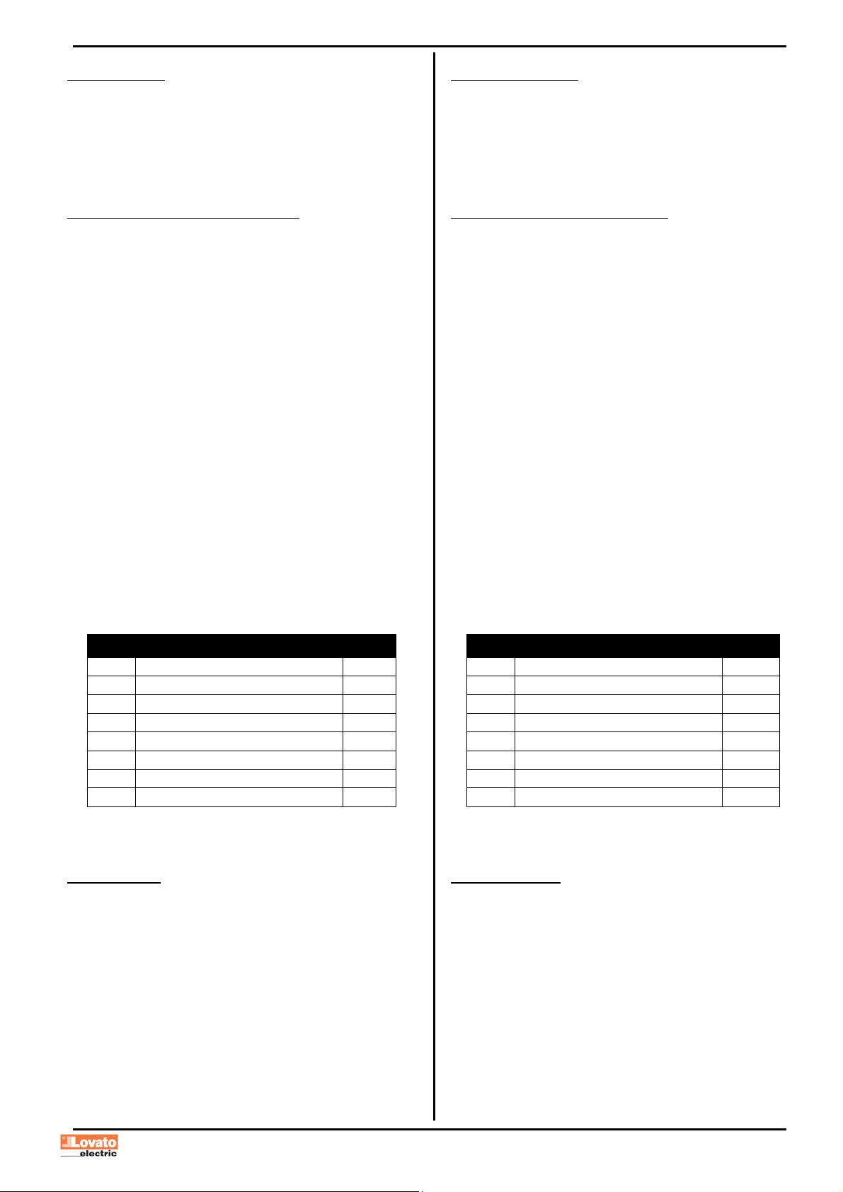
Poniższa tabela pokazuje wszystkie grupy WEJ/WYJ i wewnętrznych
zmiennych dostępnych w DMG700.
KOD OPIS ZAKRES
INPx Wejścia cyfrowe 1…8
OUTx Wyjścia cyfrowe 1…8
LIMx Progi limitów 1…8
BOOx Logika Boole’a 1…8
REMx Zmienne kontrolowane zdalnie 1…8
ALAx Alarmy 1…8
PULx Impulsy zliczania energii 1…5
CNTx Liczniki 1…4
Status każdego I/O lub wewnętrznych zmiennych może byćwyświetlony
na ekranie na dedykowanej do tego stronie.
Inputs, outputs, internal variables, counters
The inputs and outputs of the expansion modules are identified by a
code and a sequence number. For instance, the digital inputs are
identified by code INPx, where x is the number of the input. In the same
way, digital outputs are identified by code OUTx.
The sequence number of I/Os is simply based on their mounting
position, with a progressive numbering from left to right. For instance
the input INP1 is the first input terminal of the leftmost module, while the
subsequent inputs will be named INP2, INP3 and so on.
The DMG700 supports a maximum of 8 digital inputs and 8 outputs that
will thus be numbered INP1…8 and OUT1…8. For every I/O, there is a
dedicated setting menu that allows to specify functionality and
properties.
In a similar way, there are some internal bit-variables (markers) that can
be associated to the outputs or combined between them. For instance,
it is possible to apply some limit thresholds to the measurements done
by the multimeter (voltage, current, power, etc.). In this case, an internal
variable named LIMx will be activated when the measurements will go
outside the limits defined by the user through the dedicated setting
menu.
Finally, it is possible to manage up to 4 counters (CNT1..CNT4) that can
count pulses coming from an external source (through a digital input
INPx) or the number of times that a certain condition as been verified.
For instance, defining a limit threshold LIMx as the count source, it will
be possible to count how many times one measurement has exceeded
a certain limit.
The following table groups all the I/O and the internal variables
managed by the DMG700.
CODE DESCRIPTION RANGE
INPx Digital inputs 1…8
OUTx Digital outputs 1…8
LIMx Limit thresholds 1…8
BOOx Boolean logic 1…8
REMx Remote-controlled variables 1…8
ALAx Alarms 1…8
PULx Energy count pulses 1…5
CNTx Counters 1…4
The status of each I/O or internal variable can be shown on the display
in the dedicated page.
Progi limitów (LIM)
Progi limitów LIMn sąwewnętrznymi zmiennymi, których status zależy
od przekroczenia limitów pomiarów zdefiniowanych przez użytkownika
(przykład: całkowita moc czynna większa niż25kW).
By ułatwićustawianie progów, które mogąposiadaćdużą rozpiętość,
każdy z nich może byćustawiony na podstawie wartości bazowej
i mnożnika (na przykład: 25 x 1k = 25000).
Dla każdego limitu LIM można przypisaćdwa progi, najwyższy
i najniższy, których znaczenie zależy od następujących funkcji:
Funkcja Min: Ta funkcja definiuje najniższy próg jako punkt zadziałania,
a najwyższy jako punkt kasowania. Zadziałanie dla progu LIM nastąpi kiedy
wybrany pomiar jest niższy, niżustawiony próg minimalny, dłużej
niżzaprogramowane opóźnienie. Kiedy mierzona wartość staje się
ponownie wyższa niżustawiony próg maksymalny, dłużej niżczas
opóźnienia, status LIM jest kasowany.
Limit thresholds (LIM)
The LIMn thresholds are internal variables whose status depends on
the out-of-limits of one particular measurement set by the user (e.g.
total active power higher than 25kW) among all those measured.
To make the setting of the thresholds easier, since the limits can span
in a very wide range, each of them can be set using a base number and
a multiplier (for example: 25 x 1k = 25000).
For each LIM, there are two thresholds (upper and lower). The upper
threshold must always be set to a value higher than the lower threshold.
The meaning of the thresholds depends on the following functions:
Min function: the lower threshold defines the trip point, while the upper
threshold is for the resetting. The LIM trips when the selected
measurement is less than the Lower threshold for the programmed delay.
When the measured value becomes higher than the upper setpoint, after
the delay, the LIM status is reset.