RoadHog RH48200 User manual

RH48200
RH60200
RH72200
RoadHog
For units
Built After May 2010
MANUAL
Operation
Maintenance
Service
Parts
Warranty
Serial number ___________________________
Date released for shipment _________________
RoadHog, Inc. 877-640-9975 www.roadhog-inc.com
PUBLICATION DATE: 09/10/13

2
INTRODUCTION
Thank you for your investment in Roadhog Inc. We are confident that you will find that
your Roadhog Inc is the easiest to operate, safest, most durable, and most efficient
attachment on the market.
Your Roadhog Inc is equipped with high performance, heavy duty components. To en-
sure that these components operate properly and effectively, this manual must be fol-
lowed. If any question regarding the operation or performance of this attachment ex-
ists, contact your Roadhog Inc dealer at once.
This manual contains safety instructions, guidelines for efficient operation, trouble-
shooting tips, and service maintenance procedures. When applicable, the terms “right”
and “left” are referenced from a sitting position and facing forward in the loader.
Throughout this manual, information is provided in boxes and highlighted by the word
IMPORTANT. This information should be read carefully. If complied with, it will
improve the operating efficiency of the unit and provide directives that will minimize
costly breakdowns and extend the life of the machine.
This warning symbol appears throughout this manual and
indicates that a safety hazard may exist if the information
given is not properly followed. When the warning signal is
encountered in the manual or on the unit, Be Alert! Your
personal safety is involved!
For more copies of this manual or the necessary safety decals, contact your Roadhog
Inc dealer.

3
TABLE OF CONTENTS
Page
SAFETY DECALS …………………………………………………………………………….4
SAFETY PRECAUTIONS …………………………………………………………………..5
MANDATORY SAFETY SHUTDOWN PROCEDURE ……………………………………5
SAFETY ………………………………………………………………………………………..6
SETUP ………………………………………………………………………………………….7
OPERATION …………………………………………………………………………..…..8-17
MAINTENANCE AND SERVICE……………………………..………...…………...…18-26
CHASSIS GROUP PARTS DRAWING……….………………………...……………..27-28
ATTACH GROUP PARTS DRAWING……….………………………...….……...…...29-34
DRIVETRAIN AND DRUM GROUP PARTS DRAWING…...………...……….….....35-36
ENGINE GROUP ……………………..……….……………………………....………...37-38
CLUTCH GROUP ………………………………………………………………………..39-40
HYDRAULIC GROUP PARTS DRAWING……………………………………….…...42-43
HYDRAULIC VALVE ( DEPTH , TILT AND SIDE SHIFT )PARTS DRAWING……44-
45
HYDRAULIC VALVE ( CLUTCH ) PARTS DRAWINGS…………………….……...46-47
HYDRAULIC TANK PARTS DRAWINGS…………………………………………….48-49
HYDRAULIC SCHEMATIC...……………………………...….……………………..…….50
ELECTRICAL DISCONNECT POINTS PRIOR TO WELDING…………….…………..51
ELECTRICAL GROUP ( MASTER PANEL)………………………………………… 52-53
ELECTRICAL SCHEMATICS………….…………………...……………….…..……..54-56
DECAL GROUP PARTS LIST………...…….…………………………...…………….57-58
SPECIFICATIONS ……………………………………………...….………………………..59
WARRANTY ………………………………………………………...……………………….60
WARRANTY CLAIM FORM………………………………………..…………………...….61
NEW MACHINE DELIVERY REPORT…………………………………………………….62
OWNER INFORMATION CARD……………………………………………………………63
4
SAFETY DECALS
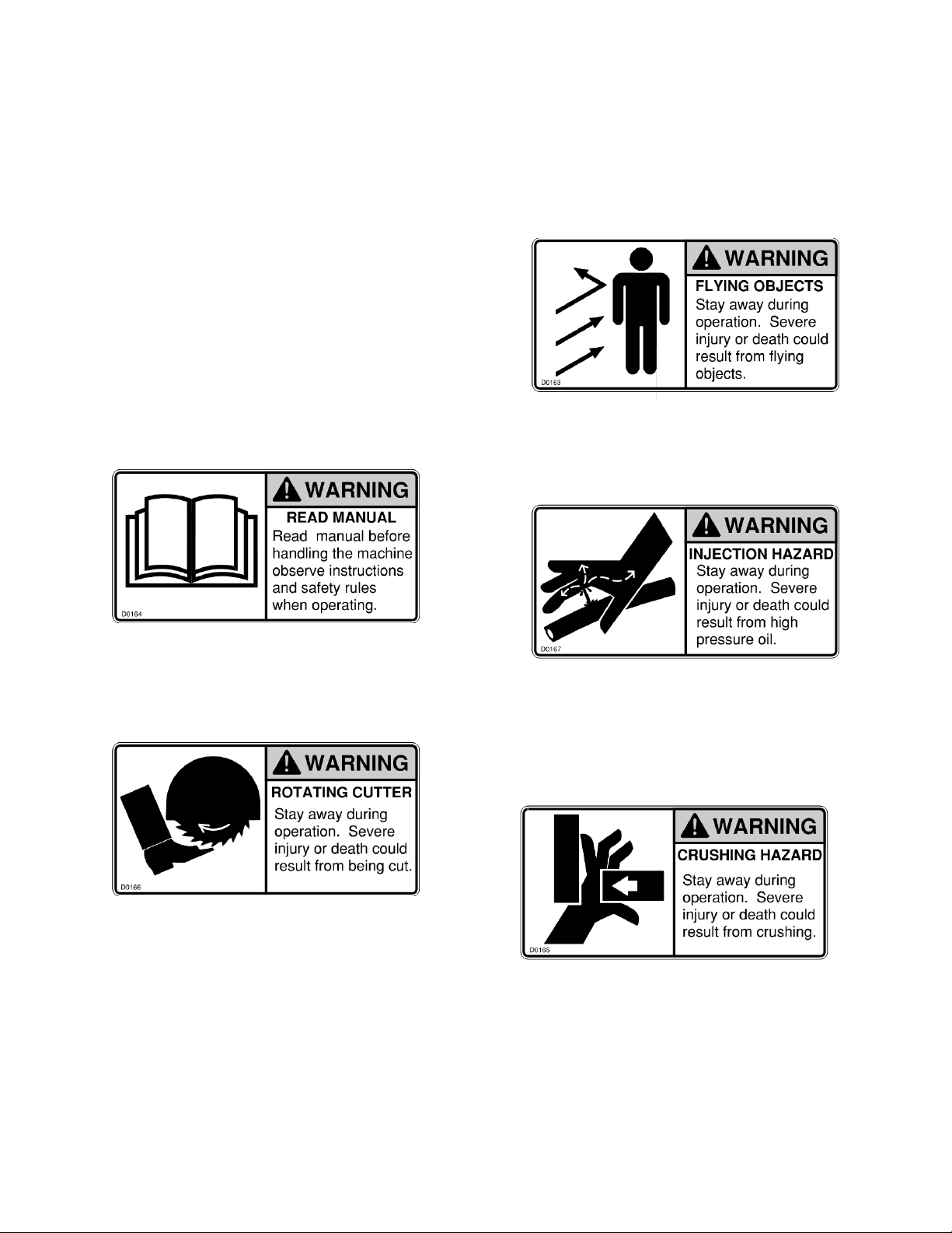
The safety decals existing on the
attachment should be clearly read-
able and always followed. The lo-
cation and description of the de-
cals is shown in the parts diagram.
The CRUSHING HAZARD decal
warns the operator and bystanders
to stay away during operation.
The ROTATING CUTTER decal
warns the operator and bystanders
to stay away during operation.
The READ MANUAL decal warns
the operator to read this manual
before operating the attachment. The INJECTION HAZARD decal
warns the operator and bystanders
to stay away during operation.
The FLYING OBJECTS decal
warns the operator the operator
and bystanders to stay away dur-
ing operation.
5
SAFETY
PRECAUTIONS
ACCIDENTS ARE
PREVENTABLE WITH YOUR HELP
Understand and comply with applicable
laws and regulations.
Call local utilities before you dig.
1-888-258-0808
Know the location of underground gas, water
and electrical lines.
Inspect area for holes, drop-offs, or unstable
ground.
Know the weight limitations of operating
surfaces and clearances.
Remember: Safe operation begins with the
operator.
BEFORE OPERATING THIS
EQUIPMENT, THE FOLLOWING
SAFETY INFORMATION SHOULD BE
READ AND UNDERSTOOD. IN
ADDITION, EACH INDIVIDUAL
WORKING WITH THE EQUIPMENT
SHOULD BE FAMILIAR WITH THE
SAFETY PRECAUTIONS
Exercise extreme caution when attaching and removing the attachment, operating with
other workers present, and servicing the unit.
Roadhog Inc makes operator safety a priority when designing machinery. Exposed
moving parts are guarded whenever possible for safety. However, not all moving parts
can be shielded in order to ensure proper operation. This operator’s manual and safety
decals on the machine provide important safety information when observed closely If
safety decals become difficult to read, replace them immediately. (see “Safety De-
cals”).
MANDATORY SAFETY
SHUTDOWN
PROCEDURE
BEFORE cleaning, adjusting, lubricat-
ing, or servicing this unit, ALWAYS fol-
low the MANDATORY SAFETY SHUT-
DOWN PROCEDURE:
1. Lower loader arms and roll attach-
ment forward until it is flat on the
ground.
2. Apply loader parking brake and stop
the loader engine.
3. Remove loader key and keep with
you while you are working on the at-
tachment.
4. Turn cold planer engine off and lock
control panel using the PIN security
feature.
FAILURE TO FOLLOW THE
PROCEDURES BEFORE CLEANING,
ADJUSTING, LUBRICATING, OR
SERVICING THIS UNIT COULD LEAD
TO SERIOUS INJURY OR DEATH.
WARNING
WARNING

6
SAFETY
A careful operator is the best protection
against accidents. Most accidents involv-
ing operators of industrial equipment are
caused by failure to observe basic safety
precautions. Know the equipment and
worksite before you operate. Familiarize
yourself with the safety precautions listed
below.
THE FOLLOWING PRECAUTIONS
MUST BE OBSERVED FOR THE
SAFETY OF THE OPERATOR
AND/OR SERVICE PERSONNEL.
1. Read and observe all safety infor-
mation and decals on the skid steer
loader and attachment BEFORE
operating the unit!
2. Refer to the SAFETY section of your
loaders operator’s manual and ob-
serve all safety recommendations set
forth in the manual.
3. When loading, keep attachment as
low to ramps & trailer as possible.
4. Always lower the loader arms fully
before leaving the operator’s seat.
NEVER CRAWL UNDER RAISED
LOADER ARMS.
5. BE SURE to raise the attachment
totally off the ground BEFORE side
shifting.
6. CAREFULLY inspect ALL hydraulic
hoses and connections on a routine
basis; Always use a piece of card-
board when searching for leaks.
7. BE SURE to exercise the above
MANDATORY SAFETY SHUTDOWN
procedure, BEFORE proceeding with
any work on the attachment.
NEVER USE YOUR HANDS AS
ESCAPING FLUID UNDER PRESSURE
CAN PENETRATE THE SKIN CAUSING
SERIOUS INJURY. IF HYDRAULIC
FLUID DOES PENETRATE THE SKIN,
SEEK IMMEDIATE MEDICAL
ATTENTION BY A DOCTOR FAMILIAR
WITH THIS TYPE OF INJURY OR
GANGRENE MAY RESULT.
NEVER ALLOW HANDS OR FEET
NEAR ANY WORKING PART OF THE
ATTACHMENT UNLESS THE
MANDATORY SAFETY SHUTDOWN
PROCEDURE HAS BEEN
COMPLETED.
WARNING WARNING
WARNING
WARNING

7
READ THIS ENTIRE MANUAL AS
WELL AS THE DECALS ON THE
ATTACHMENT BEFORE ATTEMPT-
ING ANY MAINTENANCE, SERVICE
OR SETUP OF THE UNIT.
SETUP
Hoses / Fittings
Hydraulic fittings are used to connect
all hoses. All fittings should be tight
and free of hydraulic leaks. Hoses
must be free of crimps or cuts that
might result in leakage. Check your
attachment before operation to make
sure all hose routings are kink-free and
allow for maximum movement of all
depth and side shift functions required
during normal operation.
Drum Assembly
For proper operation, teeth must be
installed in every holder on the drum.
Welds on holder and blocks should
be inspected weekly for cracks. Any
cracks should be fixed as soon as pos-
sible. Teeth should be inspected daily
for wear. Tooth should be allowed to
freely rotate within their holders.
Holders should be inspected daily for
wear. Holder wear is not typically cov-
ered under warranty. Holders may be
hard-faced to replace worn holder ma-
terial.
WARNING
Although the Roadhog Inc is supplied
fully assembled, some simple checks
should be performed before operation
begins.
Safety Decals
The safety decals existing on the attach-
ment should be clearly readable and al-
ways followed. The location and descrip-
tion of the decals is shown in the explod-
ed diagram. Copies of the decals are
shown in “Safety Decals” section.
Lubrication
The dead shaft bearing, supporting the
left hand side of the drum, should be lu-
bricated at least once a week. Daily
lubrication may be required during heavy
use or in extremely dusty conditions.
The planetary oil should be changed af-
ter the first 50 hours of operation, and
then once a year after that.

8
OPERATION
The cold planer is an engine powered attachment intended for cutting asphalt or con-
crete surfaces. The performance of the attachment can vary greatly depending upon
how it is used and operated. Therefore, the recommended operating procedures con-
tained within this manual should be followed at all times for maximum productivity.
Prior to operating the attachment, read this entire manual. Follow all safety guidelines
in this manual and safety decals on the unit. Make sure that all guards, shields, and
decals are in place and in good condition prior to operation.
Attaching to Loader
Pin on style mounting
To attach the unit to the loader, start the loader and rotate the coupler out. Move
the machine forward and align the male bosses on the male portion of the loader
attach with the female bosses on the Roadhog. Insert pins and secure pins to boss-
es per the manufacturers recommended procedure.
Attaching to Loader
quick attach style mounting
To attach the unit to the loader, start the loader and rotate the quick coupler out.
Move the machine forward and align the
male portion of the quick attach on the loader with the female portion of the quick
attach on the Roadhog. Secure the quick attach per the manufacturers recom-
mended procedure.
WARNING
ALWAYS follow the loader manufacturers recommended procedures for mounting
attachments to the loader. Refer to attachment mounting instructions in the loaders
operating manual. Severe injury or death could result from crushing.
GENERAL CONTROL SYSTEM
Units can be operated from either the panel or using the radio controller. The
master panel has illuminated push buttons that change colors during operation which
indicate the following and provide visual feedback to the operator.
RED—indicates that a function cannot be operated.
GREEN—means it can be operated
Flashing GREEN—tells the operator which mode or function is currently active.
Amber—used to tell the operator the water kit is in auto mode and slave to the clutch.

9
Loader operation
1. Clear all bystanders.
2. Enter loaders operator platform.
3. Engage parking brake.
4. Start loader.
5. Start Roadhog ( see instructions on pages
10 thru 13 of this manual )
4. Roll out the loader bucket function so that the Roadhog
depth skis are level and in full contact with the pavement.
5. Lower the Roadhog cutting drum to the desired depth per
instructions on pages 10 thru 13 of this manual.
6. Apply the foot brake.
7. Place the loaders transmission in 1st gear.
Loader engine should be at idle.
8. Release parking brake and foot brake. This step will start
the cutting operation.
NOTE: Cutting drum feed rate and loader ground speed)
is dependent upon depth of cut, age of pavement,
size and type of aggregate in pavement, density of
pavement and ambient temperature.
9. Loader ground speed should be adjusted up or down
after the above factors in step 8 have been evaluated.
10. Adjust loader’s engine rpm and the loader’s ground speed to
maximize the load on the Roadhog’s cutting drum.
11. If the cutting drum on the Roadhog stalls, back up the
loader or lift or curl the Roadhog out of the pavement using the
loader’s bucket function.
WARNING
ALWAYS follow the loader’s manufacturers recommended operating procedures found in
the loader manufacturer’s operating manual for proper operation of the wheel loader.
Severe injury or death could result from improper operation of the wheel loader.
WARNING
If an emergency arises, immediately apply the wheel loader’s brakes and
Stop the wheel loader’s engine and the Roadhog’s engine.
The Roadhog’s engine may be stopped by pushing the red shutdown
button on the master panel or by pushing the red emergency stop button
on the remote transmitter.

10
LCD Display Screens
Home Page Home Page w/ menu button
Contrast Page Up/Down Setup Menu
Home Page - Sub-Screens
Note: After activation the buttons, to move between sub screens just pr ess the page up/down button.
Note: Scr een 2 displays; hour meter , tor que
percentage, fuel efficiency, and voltage options.
Note: Scr een 3 displays; RPM, oil pr ess, and
engine temperature.
Setup Main Menu and Sub-Screens
Note: To enter setup menus, press the setup
button on the home page.
Note: The display is not a touch scr een. Ther e ar e buttons just below each image on the screen. To pull up
the function buttons press the left button once. That will activate the screen options. Push the button to activate the
function.

11
LCD Display Screens (continued)
Home Page with just power on
Changes to screen during operations of Road Hog
Home Page with e-stop on panel
Home Page engine on in panel mode Home Page engine on in radio mode
Home Page clutch engaged Home Page water kit on
Home Page water kit slave to clutch

12
STARTING PROCEDURE- USING MASTER PANEL ON ROADHOG
This procedure requires another operator at ground level.
Engine start
1. Follow all safety procedures.
2. Turn power switch until the control panel lights up.
3. Ensure radio button is in “panel” mode (PANEL will display on LCD screen & button will
be constantly green).
4. Turn and pull red shutdown button out on master panel.
5. Press “engine start” button on master panel until engine starts.
Drum drive engagement
1. Follow all safety procedures.
2. Allow engine to run for 2 to 3 minutes.
3. Push “engine throttle” button on master panel for 2 seconds to engage high idle.
4. Hold “clutch engage” button on master panel for 4 to 8 seconds (Button will flash green)
NOTE: momentary delay of engagement is normal
This engagement may take longer in cooler temperatures.
Drum depth engagement
1. Press and hold “depth down” button on master panel down lower the cutting drum
until the desired cutting depth is reached. Press the “depth up” button on master
panel up to raise the cutting drum. Release button once desired depth is reached.
Side shift engagement
1. Press and hold “side shift” button on master panel. Hold until desired position is
reached. Release button
Tilt engagement IMPORTANT: Always preset the desired angle and depth of cut prior to
making
the cut.
1. Press and hold the “tilt” button until the desired angle is reached.
2. Press and hold the “ depth down” button until the desired depth of cut is reached.
3. Lower the drum into the cut by lowering the loader arms. Only one ski will contact the ground.
Normal shutdown proce- dure using master panel ( non-emergency only )
1. Press “ clutch disen- gage” button to disengage clutch and drum
2. Press “ engine throttle” button on master panel to engage low idle
3. Press red “shutdown” button on master panel to stop engine

13
STARTING PROCEDURE- USING MASTER PANEL ON ROADHOG
(continued)
This procedure requires another operator at ground level.
Water Kit Control
1. Once the engine is started.
2. Press “water kit button” button on master panel once to start the pump. (Button will flash
green when on)
3. Press “water kit button” button on master panel twice to activate slave to clutch.
(Button will be solid amber when in auto)
4. Press “water kit button” button on master panel three times to stop the pump. (Button will
be solid green when off)
Fully lower the loader arms and then roll out the bucket function until the planer skis are level with
the pavement.
Move the throttle to the full rpm position. and keep it there during the milling operations. Begin the
operation by setting the depth cylinders to zero depth at the depth gauge. Lower the drum into the
cut to the desired depth. Move forward at a speed that will allow the drum to mill or cut efficiently
without stalling.
NOTE. Milling speed will depend on tooth condition, age and density of the material, aggregate
size and ambient temperature.
14
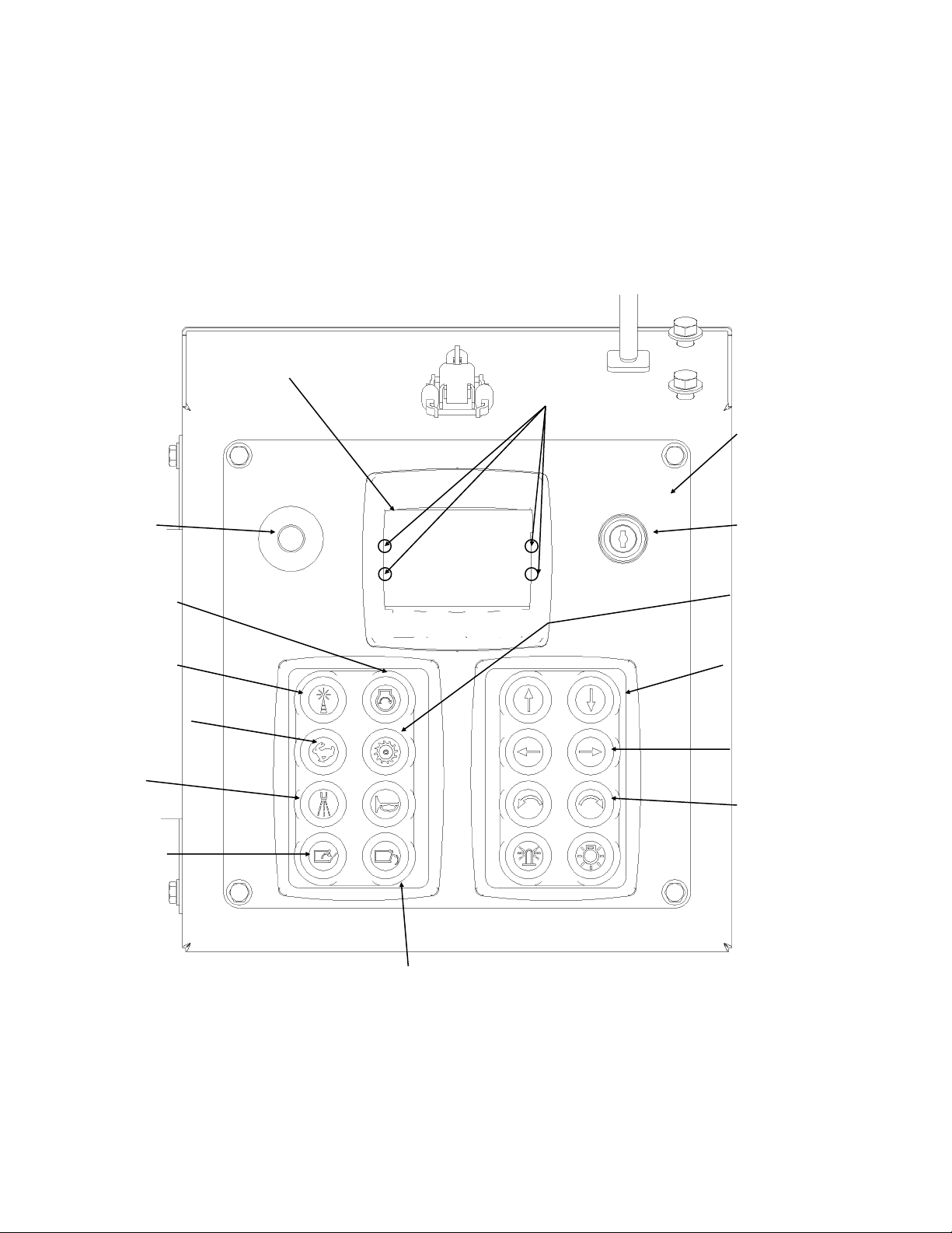
Diagram of master panel
Power key switch
Master panel
Shutdown
button
Radio/panel
Engine start
Engine throttle button
Clutch engage/
disengage switch
Depth buttons
Side shift buttons
LCD display
Tilt buttons
Water kit button
Hood open button
Hood close button
Warning/Error
Lights

15
STARTING AND OPERATING PROCEDURE - USING REMOTE TRANSMITTER
This procedure may be done at ground level using an additional operator, or may
be done by a single operator from the wheel loader’s operator seat.
Engine start
1. Follow all safety procedures
2. Turn power key until the master panel lights up.
3. Press ON button.
4. Ensure master panel button is in “ radio” mode (RADIO will display on LCD screen and
button will flash green).
5. Check for green power indicator light on remote transmitter
6. Turn and pull red stop button “out” on master panel
7. Press “fuel run/stop” button on remote transmitter once
1. Press “engine start” button on remote transmitter until engine starts
Drum drive engagement
1. Follow all safety procedures
2. Allow engine to run for 2 to 3 minutes.
3. Press “throttle high/low” button on remote transmitter once to engage high idle
4. Press “ clutch engage” button on remote transmitter for 4 to 8 seconds to engage drum
NOTE: Momentary delay of engagement is normal
This engagement may take longer in cooler temperatures.
Drum depth engagement
1. Press and hold “drum down” button on remote transmitter to lower the cutting drum until the
desired cutting depth is reached. Use the drum up arrow button
on remote transmitter to raise the cutting drum.
Side shift engagement
1. Press and hold “side shift” button on remote transmitter. Hold
until desired position is reached. Release button
Tilt engagement IMPORTANT: Always preset the desired angle and depth of cut prior to mak-
ing
the cut.
1. Press and hold the “tilt” button until the desired angle is reached.
2. Press and hold the “ depth” button until the desired depth of cut is reached.
3. Lower the drum into the cut by lowering the loader arms. Only one ski will contact the ground.

16
STARTING AND OPERATING PROCEDURE - USING REMOTE TRANSMITTER
This procedure may be done at ground level using an additional operator, or may
be done by a single operator from the wheel loader’s operator seat.
Normal shutdown procedure using remote ( non- emergency only )
1. Press “ clutch disengage” button to disengage clutch and drum
2. Press “ throttle high/low” button to engage low idle
3. Press “ fuel run/stop” button to shut off fuel flow

17
Emergency stop button/Key
Drum side shift right
Drum side shift left
Drum up
Drum down
Power indicator
Throttle button Clutch engage/disengage button
Tilt left button
Engine start button
ON/Fuel button
Diagram of Radio
Tilt left button
Display

18
MAINTENANCE
Proper maintenance of the attachment will
result in longer life and the more produc-
tive and cost effective operation. There are
two basic categories of maintenance re-
quired, pick/holder replacement and
component lubrication. For proper opera-
tion, the picks should be checked each four
(4) hours and lubricated daily with a water
based emulsifying agent to ensure that they
can freely rotate in their holders.
BEFORE PERFORMING ANY
MAINTENANCE ON THE UNIT, PER-
FORM THE MANDATORY SAFETY
SHUTDOWN PROCEDURE.
WARNING
Pick/Holder Replacement
As regular use takes place, normal wear of
the carbide picks will occur with the outer
most picks wearing first. The pick tool in-
cluded with the cold planer should be use
to remove the picks from the cast holders.
In the event the pick tool is not available,
any hardened punch or tool allowing ac-
cess to the bottom of the holders can be
used.
IMPORTANT
Welder must be grounded directly to drum
during pick holder replacement or SEVERE
BEARING DAMAGE WILL RESULT.
A length of pipe with a 3/4 to 1 inch inside
diameter can be placed over the pick to pro-
tect it from a direct hit. Striking a small piece
of wood placed on the pick to absorb the
shock will prevent damage.
NEVER DRIVE THE PICK BY STRIK-
ING DIRECTLY ON THE END OF THE
PICK AS THIS CAN CAUSE THE PICK
TO CHIP AND CAUSE INJURY OR
CREATE SMALL STRESS FRAC-
TURES IN THE PICK, RESULTING IN
PREMATURE WEAR.
WARNING
ALWAYS WEAR SAFETY GLASSES
WHEN PERFORMING THIS OPERA-
TION. HARDENED TOOLS AND PICKS
CAN SHATTER CAUSING INJURY.
WARNING
The factory installed carbide pick chosen
for use is a general purpose pick as the
cold planer is designed for both asphalt
and concrete applications. Picks de-
signed for extended periods of concrete
cutting are available from the factory or
your dealer.
To prevent the picks from seizing in the
holders, the picks should be sprayed
with a lubricate at the end of each day.
This will break down the asphalt build up
in the holders and prevent premature
wear by allowing the picks to rotate in
the holders. Excess lubricant should be
caught in a collection pan and properly
disposed of.
If the pick remains in the holder beyond
its intended replacement point, it reduces
the cutting performance and will not pro-
tect the holder. Inspect the cutting drum
every 30 minutes of operation. Check
the picks and holders for wear. If the
picks are worn enough to indicate slight
holder wear, replace the picks.
NOTE: always disconnect the ECU, radio
receiver and master panel prior to any
welding.
See page 39 for these 3 locations.
19
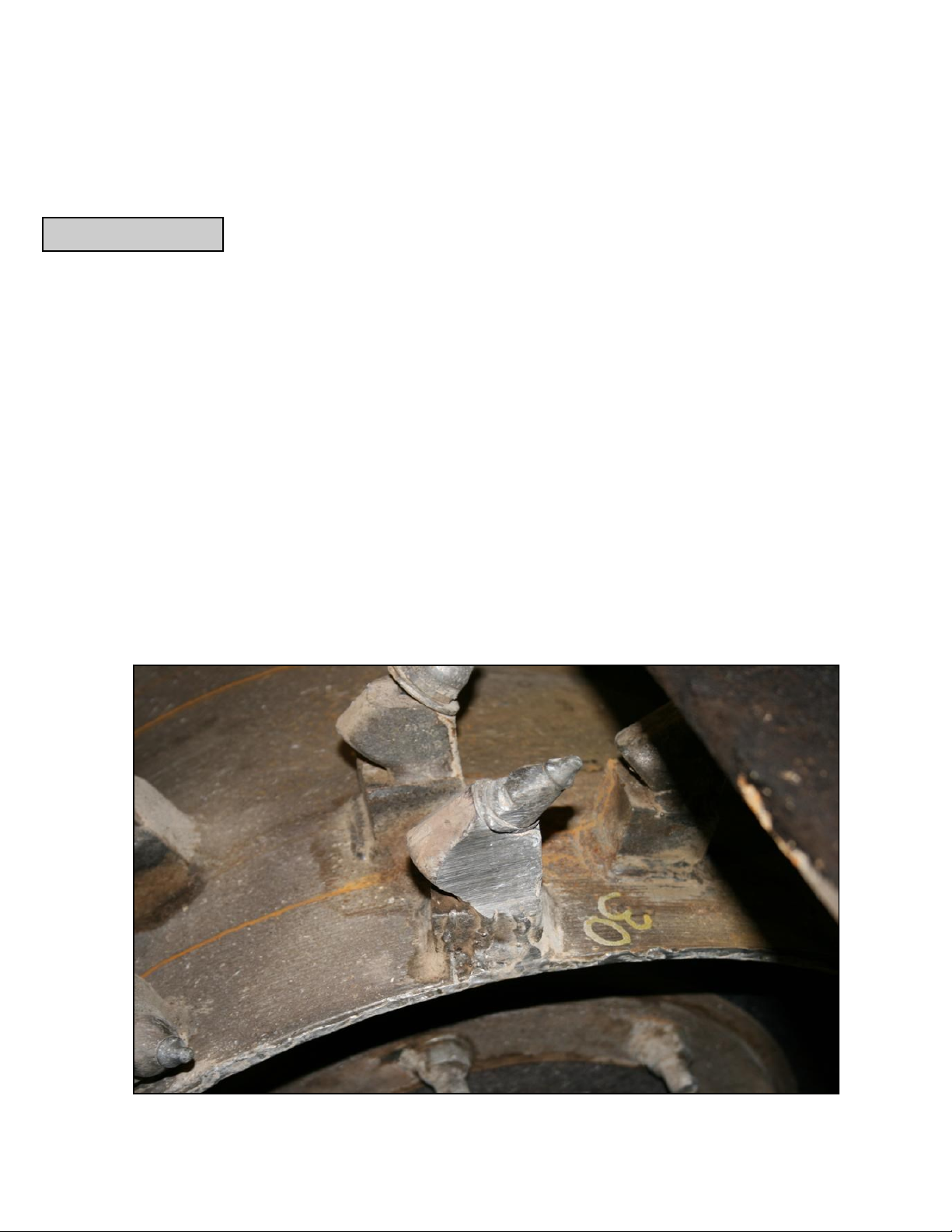
Tooth is no longer rotating in the holder, causing premature tooth and holder wear.
Tooth maintenance ( and rotation ) is critical to extending the life of the tooth and tooth holder and overall production of
the RoadHog.
Check the condition of the teeth every 30 minutes, until wear patterns are determined under current conditions.
Tooth life varies with depth, density, material, aggregate and maintenance, which includes allowing the tooth to rotate.
Various tooth styles are available to match material and aggregate variables, which may increase tooth life and production.
Consult the factory for further assistance.
The tooth has two functions: serves as the consumable cutting tool and it protects the holder.
The tooth must be allowed to rotate in its’ holder. If it locks up, then tooth and holder wear is greatly accelerated
If the tooth is allowed to remain past its’ usable life, the holder will exhibit premature wear characteristics. ( see photo below ).
To promote rotation, spray the teeth daily with a water based asphalt emulsifier to break down asphalt emulsion.
Example: Zep’s Orange Response ( part number 0750 ).
Water should always be used, as it may increase tooth life by 20 to 40% and suppresses the milling dust.
Edge teeth will always wear faster than center teeth, due to side loading of the drum during the loader’s steering corrections.
Edge holders and drum edges are hard-faced at the factory and will be required throughout the machines life.
Tooth Maintenance
IMPORTANT

20
Warranty will not be allowed for failure due to the following: normal wear and tear, abuse or accident, excessive
flow or pressure, modification of original equipment, improper service or maintenance.
Roadhog does not warrant ANY ground engaging parts ( drums, teeth, holders or bases )
against wear, unless the wear is determined by Roadhog to have been caused by an engi-
neering or manufacturing defect.
Teeth may last twice as long if they are free to rotate in their holder
Rotating teeth Non-rotating teeth
Examples of remaining tooth life ( % )
100 95 90 75 40 20 0 -5
This manual suits for next models
2
Table of contents
Other RoadHog Construction Equipment manuals


