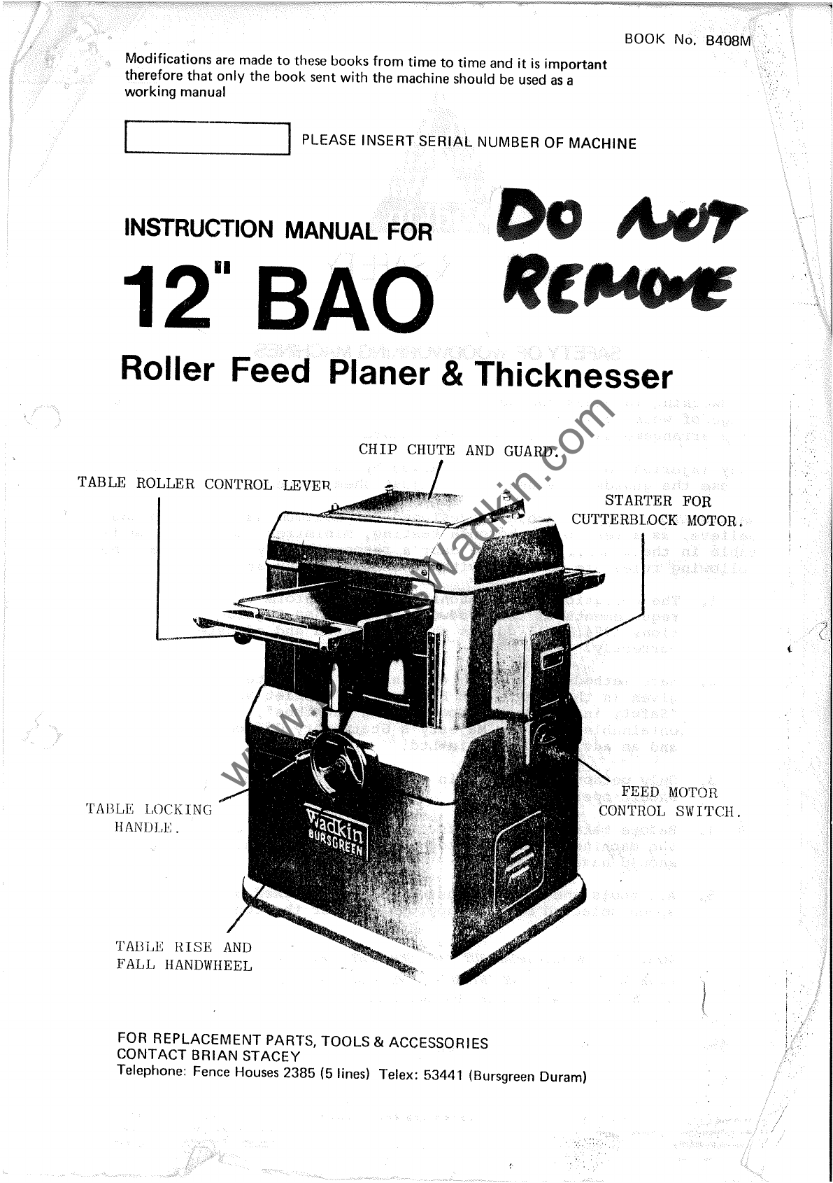
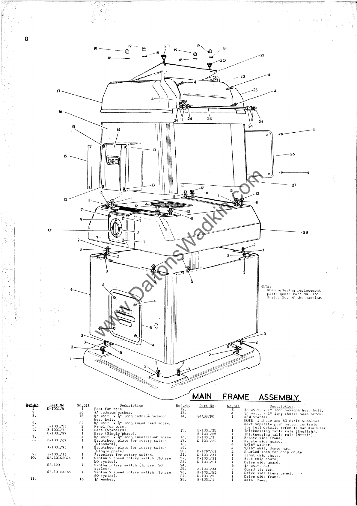
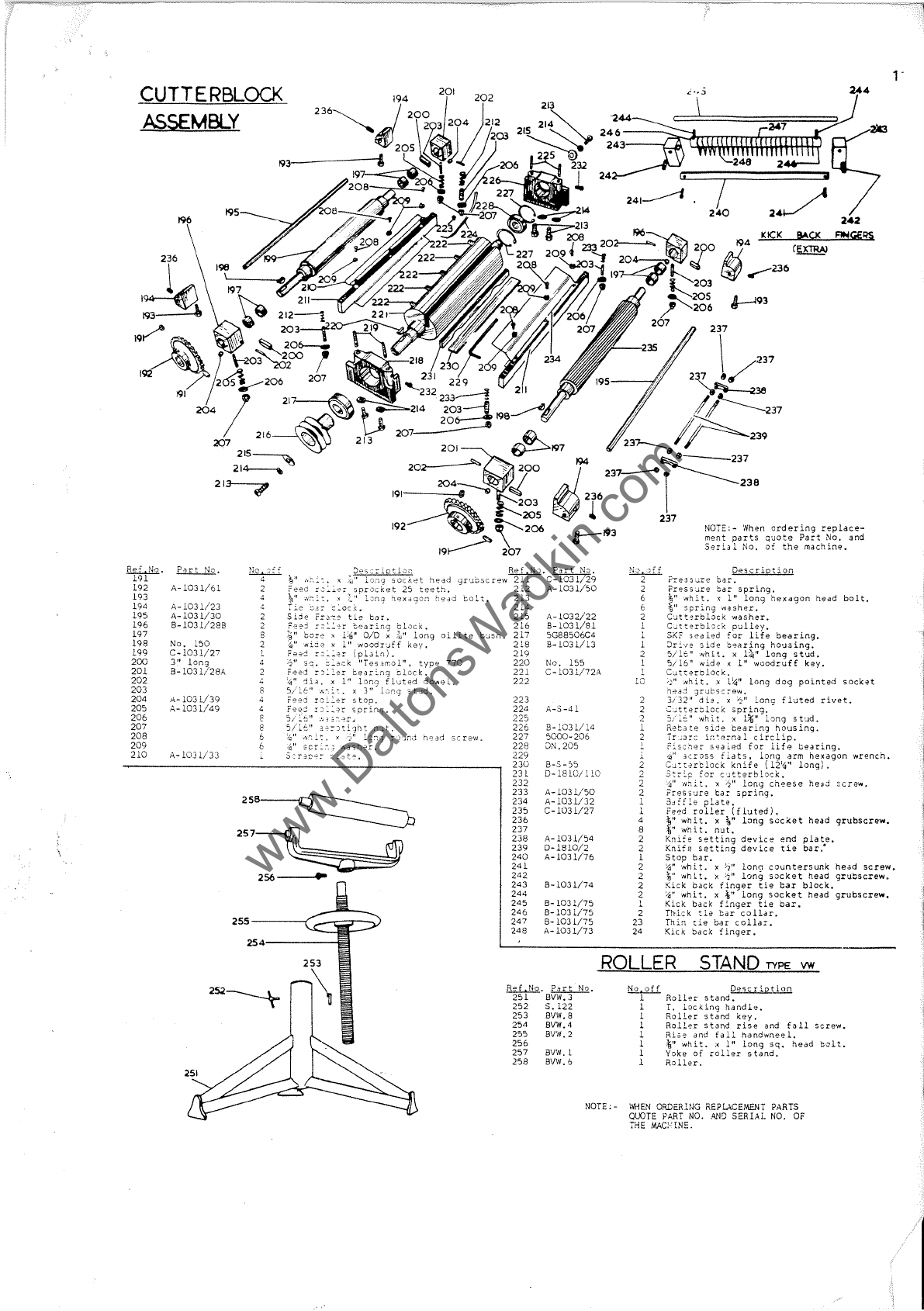
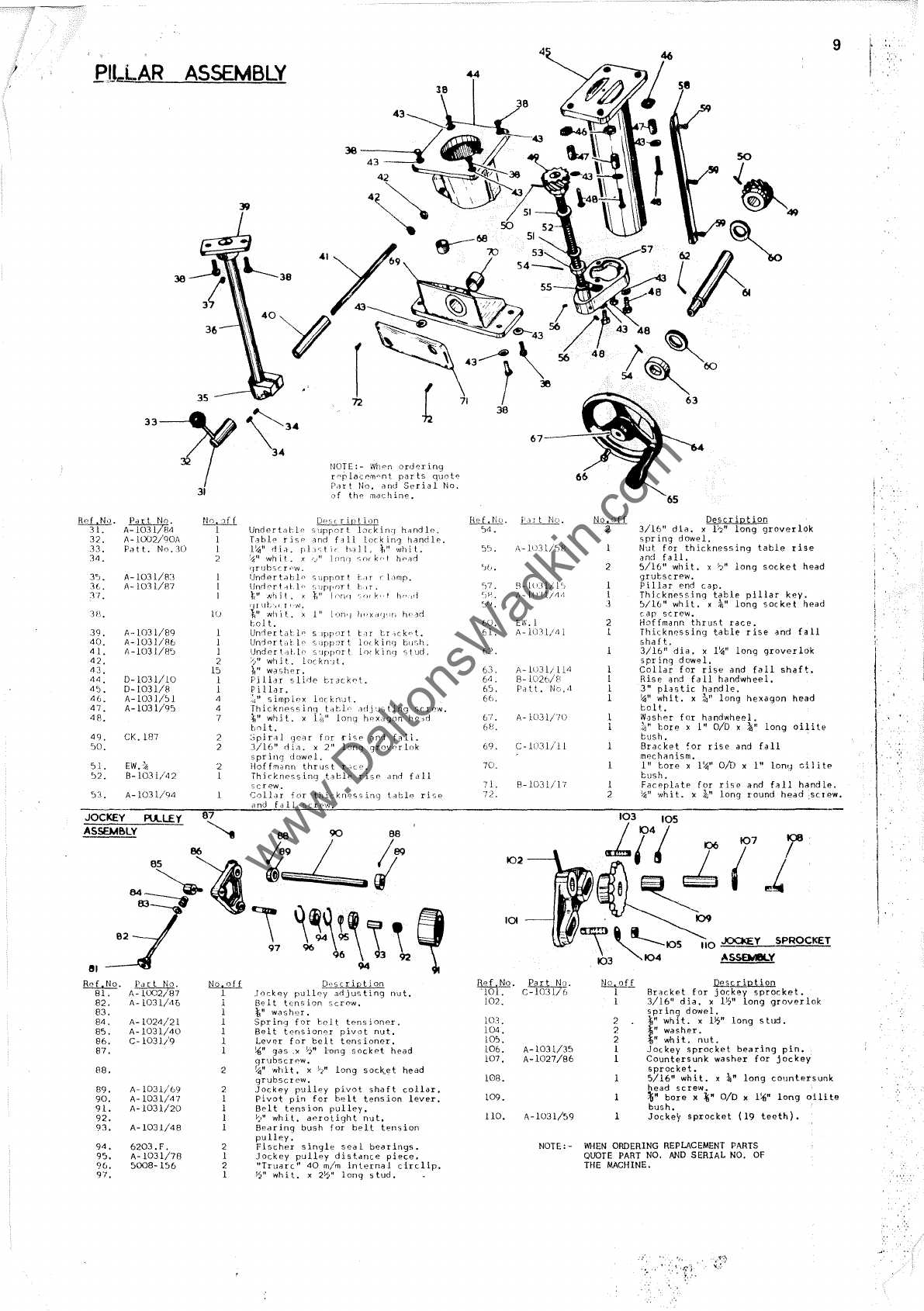
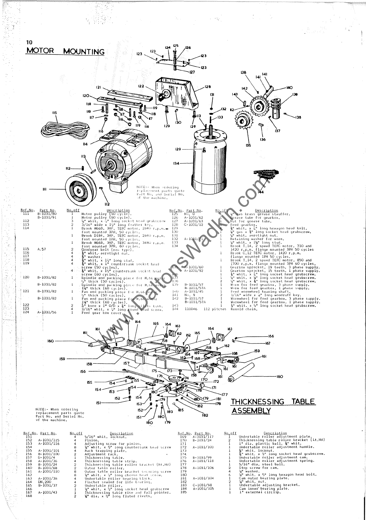
Wadkin BURSGREEN BAO User manual

BOOK No. B408M
Modifications
are
made
to
these
books
from
time
to
time and
it
is
important
therefore that
only
the book sent with the machine should
be
used
as
a
working manual IPLEASE INSERT
SERIAL
NUMBER OF MACHINE
--------------~
INSTRUCTION
MANUAL
FOR
Roller Feed Planer &Thicknesser
TABLE
ROLLER
CONTROL
LEVER.
'1'AI11.E
LOCKING
IIANDLI':
.
TABLE
IUSE
AND
FALL
HANDWHEEL
CHIP
CHUTE
AND
GUARD.
FOR REPLACEMENT PARTS, TOOLS & ACCESSORIES
CONTACT
BRIAN
STACEY
STARTER
FOR
CUTTERBLOCK
MOTOR.
FEED
MOTOR
CONTROL
SWITCH.
Telephone:
Fence
Houses
2385
(5
lines) Telex: 53441 (Bursgreen Duram)
1
,
I'
www.DaltonsWadkin.com

:-,-,-
..
"
Application
Castrol
Worm
Boxes
Alpha
617
General
Magna
ED
Lubrication
Pneumatic
Hyspin
Lubricators
AWS
32
Grease
Spheerol
AP.3
Brake
Brake
cable
Cables
grease
BURSGREEN (DURHAM)
LIMITED
APPROVED
LUBRICANTS
Approved
Lubricant
B.
P.
Shell
Esso
Energol
CS425
Vitrea
75
Pen-O-Led
E.
P.3
Energol
Vitrea33
Esstic
50
HP.20
Energol
Tellus
Nuto
HL
65
27 H 44
Energrease
Alvania
3
Beacon
3
LS.3
Starfak
Premium
3
Energrease
Alvania
Multi
-purpose
L21M 3
grease
H
.j
!
":-'
..
-
Texacoj
Wadkin
Caltex
Regal
L.2.
Oil
J
Ursa
Oil
L.4.
P.20
Rando
Oil
HDA
Regal
L.6.
www.DaltonsWadkin.com

5
SPECIFICATION
Length
of
thicknessing
table.
Ov"r311
len,)th
includinq
J.lter
roll",rs
..
Capacit
of"rnachine
•...
C.Jttinq
circlo
diilrTIpl"r of
Cllttr,!
.lock
•.
Speed
bf
cuttnrblock
•..
~uffibpr
of
cutters:
5landard
..
Uptional
extra.
H.F.
of
Clt
lerblcck
motor.
...
S ri
spoed
of
culterblock
motor:
~O
cycles.
U)
c,(cles.
Diameter
of
fo"j
rJllers
Feed
speeds
per
minute:
3
p~ase
•..
Floor
spac".
Net
weight.
Table
Roller
Control
Lever
Table
Locking_---'
__
Handle.
Table
Rise
and
Fall
Handwheel
IN"T
ALLATlON
1
phase
.•.
FIG.
I.
Remove
orolective
coating
from
Lright
parts
by
applying
d
c~oth
soaked
in
paraffin,
lJrpentine
or
oth"r
sol""nl.
iVti!'n
rTi;lc~inp
is
cased
for
expol
t,
the
outer
t"f;jn
rol,ors
~nd
[is"
and
fall
hand'Nheel
are
removurj and
packed
in
the
parcel.
Removp
and
re-
u:"sn:nLlc:)
;;s
sh:)wn
in
fig.
1.
To
Rpversp
Direction
Ch~n?e
,;
2 and 13:t
To
Reverse
Direction
Chanqe
11:;
anj
B-3
L'>.'Ur1I--t-'L.L:.._L
J
lz
L-M""-''---L
I
'-------'
~IRING
DIAGR~~
FOH
THREE
FH~3E
3JPPLY.
FIG.2.
28
"
3:'//'
12'il"wide x
7"
4"
5,000
rpm
2
3
3
3,000
rpm
3,600
rpm
2"
15
&
30ft.
22ft.
35;;''' x
25>2"
620
lb.
WIRING
DETAILS
deep
710mm
900mm
3l0mm
x
180mm
lOOmm
5,000
rpm
2
3
3
3,000
rpm
3,600
rpm
50mm
4,5
&
9m
6.7m
900mm
x
650mm
275
kg.
The
motor and
control
gear
have
been
wired
in
before
despatch.
All
that
is
required
is
to
connect
the
power
supply
to
the
starter.
Points
to
note
when
connecting
to
power
supply:
1.
Check
the
voltage,
phase
and
frequency
correspond
to
those
on
the
motor
plate,
also
the
correct
coils
and
heaters
are
fitted
to
thE
starter.
2.
It
is
important
that
the
corrpct
cable
is
used
to
give
the
correct
voltage
to
the
starter
a~
running
on
low
voltage
will
damage
the
mote
3.
Check
the
main
line
fuses
are
of
the
correCL
capacity.
See
list
below.
4.
Connect
the
line
leads
to
the
appropriate
terminals.
See
Fig.
2
for
three
phase
supply.
5 Check
all
connections
are
sound.
6.
Check
the
rotation
of
both
motors
for
the
correct
direction.
If
these
are
incorrect
reverse
any two
of
the
line
lead
connections.
For
single
phase
supply
refer
to
booklet
supplied
with
starter
for
wiring
details.
Voltage
Phase.
SoW.G,
Tinned
l:.!!:!p~
550/400/440
380/420/340/380
220
20U
-250
3
3
3
I
Copper
Wire
23
22
"21
17
20
24
29
65
Fuse
capacity
should
not
exceed
three
times
full
load
current
of
machine.
Remove
Side
Panel
to
Grease
Gear
Box. 1 Turn
Per
Week
Oil
Under-
Table
L.ii~n~k~s~-J==~~~~~~~wil
Weekly.-
Grease
Both
Ends
of
Motors
2
Turns
per
Year.
LU8RICAT
ION
Oil
Slide
Pillar
Weekly
FIG.3.
It
is
advisable
to
ke!'p
all
b~ight
parts
covpred
with
a
thin
film
of
oil
to
prevent
lusting.
TYPE
OF
OIL
RECO~';iv'IEI,DE;)
('miEk
EN
..
125
TYF'E
OF
GfiEASF.
RECO;c,lt.ENDED
SHELL ALV,,N1I13.
".
i
I
I
www.DaltonsWadkin.com

~
I
; ,
6
All
adjuslnlPllts
and
alignmentH
listed
helow
hav~
IJ(:ell
carefully
bel
and
checked
and the whole machine thoroughly
tested
before
despatch
from
the
works.
During
the
first
few
weeks
of
operation
and
at
regular
intervals
afterwards
certain
items
such
as
belt
tension
and
chain
tension
should
be
checked
carefully.
When
adjust
ments
are
necessary
proceed
in
accordance
with
the
relative
instrue'ions
given.
TABLE
HOLLEHS
~~TheaiiH::ri'1crfon
table
rollers
or
bed
rollers
revolve
on
sealed
for
life
ball
bearings
which
require
no
lubrication.
On
machines
prior
to
serial
no. 63457
rollers
were
Individually
adjusted
by
set
screws
under
the
bearing
blocks
and
should
be
adjusted
to
suit
the
relevant
working
conditions,
On
all
machines
after
this
number,
the
rollers
are
automatically
adjusted
in
relation
to
the
table
surface
by a
single
operating
lever
at
the
infeed end of
the
table.
A
calibrated
scale
(0
-
3)
above
the
lever
indicates
the
relevant
positions,
a guide
to
which
is
as
follows:
At
Min. 0
-RoHers-
are
level
with
table
surface
and
only
very
fine
cuts
on
selected
pre-machined
timber
are
generally
possible
on
this
position.
Feed
permitting,
however,
very
accurate
step
free
planing
can
be
carried
out In
this
position.
Positions
I and 2.
-These
positIons
are
the
normal
ones
for
general
use,
combining
good feeding with
first
class
results.
Position
3 maximum
This
is
for
use
with wet,
twisted
or
roughly
sawn
material
where
feeding
Is
most
important
feature.
In
all
cases
the
lowest
position
consistent
with good and
regular
feeding
should
be
used
as
this
will
give
the
best
possible
results.
Should
the
table
rollers
be
removed
for
any
r"p-~on
Gare
must
be
taken
to
replace
them
exactly
as
before
'wise
the
setting
will
be
disturbed.
"
must
be
emphasised
thal
a
really
good
surface
finish
from
a
thickn!'ssing
machine
Is
only
possible
when
the
face
of
the
timber
resting
on
the
machine
table
is
flat
and
has
a
reasonable
finish.
Wherever
practicable
this
face
should
be
pre-machined
on an
overhand
jointer
Or
surfacer
to
remove
twist
and
other
irregularities.
'/ HEAR PHESSUHE
BAH
FIG.4.
FHONT PRESSUHE
BAR
FEED
ROLLER
AND
PRESSUHE
BAH
SETTINGS
~1'hese
are
pre-set
at
works
in
accordance
wHll
Fig.
4 and
tical
adjustment
relative
to
the
cutterblock
is
neither
possible
nor
necessary
provided
the
cutters
are
correctly
~set
with
the
special
setting
gauge
supplied
with
each
machine.
, Should
replacement
feed
rollers
or
pressure
bars
be
fitted
at
any
time
the
settings
should
be
very
carefully
checked
with
Fig.
4.
Some
slight
advantage
in
finish
or
feeding
may on
occasions
be
obtained
by
increasing
or
decreasing
the
tension
of
the
pressure
bar
or
feed
roller
springs.
The
springs
should
never
b~
compressed
to
a point
where
the
feed
rollers
and
pressure
bars
cannot
lift
sufficient
to
allow
the
maximum
cut
to be
taken.
BELT
TENSION
--'l'lie-curreriilock
drive
Is
by 2
Vee
belts
from
a 3
HP
motor.
Tension
is
effeeled
to
these
belts
by an
adjustable
jockey
pulley.
To
adjutit, rerllove
sheet
steel
panel
from
drive
side
of the machine
~lnd
tUrn the 'knurled
nut
"A"
in
Fig.
5 ill the
dlrectioll
indicated
until
the
required
tension
is
reached.
Replace
panel
before
operating
machine.
FEED
CHAIN
'l'IO:NSIUC;
--DrlveToIe'ca
i:ol1ers
is
by
roller
chain
frulIl
a worm
gearbox
directly
coupled to
the
feed
motor.
Feed
motor
on 3
phase
machines
is
2
speed
giving
feed
speeds
of
15
and
30
ft/min
(4.5
and
9
m/min)
and
on
single
phase,
single
speed
giving
a feed
speed
of 22
It/
min
(6.7
m/min)
only.
The
feed
chatn
must
be
run
with
sufficient
slack
to allow
the
front
or
serrated
feed
roller
to
freely
lift t" (6
01/
m)
from
rest
position.
To
adjust,
remove
drive
side
panel,
loosen
the
two
nuts
"B"
in
Fig.
5
and
move
idler
sprocket
as
required.
Check
feed
roller
lift
as
above,
tighten
nuts
and
re-
place
panel
www.DaltonsWadkin.com

8
FOH
SOFT
WCXJD
FOR
HARD
WOOD
,~4j
~L,·
11
FOH
DRY
FOR
DRY
I
C
SOFT
WOOD
o
HARD
WOOD
FIG.
7.
CUTTER
CARE
The
cutter,
supplied
1Tn
12~"I~ng
(3!~mm)
x
l~"
wide
(32
mm)
x
~"
thick
(3mm)
In
Lalanc~c
sets.
They
sho~ld
be
kept
In
balanced
sets
by
ensuring
that
the
cutters
have
equal
dimensions
after
grinding
and
that
the
cutting
edge
is
straight
and
parallel
to
the
back
For
general
work kn
angles
for
oft
and
hard
woods
arp
rec~mmanded
as
in
Fig.
7
(a
and
(b).
Whnn
a
very
fine
finish
is
requi
in
dry
soft
and
hard
woods a
slight
front
bovel
is
given
as
in
Fig.
7
(c)
and
(d).
For
wet
or
green
timber
the
cuttIng
bnvel
may
be
decreas~d
five
degrees.
but
the
front
bevel
should
not
be
given.
Keep
th0
cutters
sh0rp
when
in
position
by
using
a
Linn
qr.Jd n
oil
tono
dipped
in
par"ffin.
Allow
tho
~;t(mn
to
rost
lightly
and f
la
t
rln
the
bevel
and
pass
over
th~
cutter
with
a
rotating
action
a few
limns.
Give
about
two
stokes
on
the
full
Inngth
of
each
knife
on
th"
fac
side
to
remove
all
burrs
from
the
cutting
edge.
Do
not
allow
a
heel
greater
than
1/32"
wide
on
the
bevel
before
removing
and
regrinding.
When
the
heel
becomes
too
wide
the
knives
may
heat
up
or
hdV(~
d
hdrrHw'r
i Tlli
('
f f
(~('
t
on
thf'
WI)ud
dnd
rnOTr>
than
,,,nm;d
power
will
be
required
to
run
t.he
cutt0rblock.
SETTING
THICKNESSlNG
TABLE
PAHALLEL
TO
CUTTERBLOCK
The
machine
table
is
accurately
set
parallel
to
cutterblock
before
despatch
but
should
it
bp
dislurbed
for
any
reaspn
it
must
bp
carefully
checked
and
made
parallel
to
th~
cutterblock,
if
necessary,
by
the
following
procedure.
1.
Feed a
short.
length
of
timber
approximately
2"
square
(SO
mm)
x IB"
long
(460
mm)
through
the
machine
to
one
side
of
the
thicknessing
table.
2.
Without
adjustment
to
the
height
of
the
lable
feed
the
timber
through
the
machin
n
again
on
the
opposite
side
of
the
table
to
that
in
item
1.
3.
If
;J
cut.
i'i
l.Jknn
or
it
does
not
Lluch
the,
w,)od
ddju',l
th"
finr
thread
adjusters
on
tllf)
under-
sIde
of
the
tabl"
to
suit
and
when
sot
tighten
a 11
Se
r
0W~}
•
As
the
knife
sptting
d~vicp
sets
the
knivos
parall"l
tu
the-
(utt"r~,l()ck
it
is
vItally
important
that
the>
t~blo
le;
"t
parallel
to
th~
knivps
for
accurate
thickn~ssing.
IG.B.
THICKNESSING
RULE
The
pointer
on
the
machine
table
is
pre-set
before
despatch.
Should
it
be
disturbed,
feed
a
piece
of
timber
through
the
machine
and
measure
the
thickness
accurately.
Check
that
the
reading
given
by
the
pointer
corresponds
to
the
thickness
of
timber
machined.
Should
adjustment
be
necessary
slacken
the
screw
"A"
in
Fig.
8
and
set
pointer
to
the
correct
thickness.
7
GENERAL
H
INT~;
1.
When
thicknessing
long
lengths
of.
timber
always
'support
after
the
machine
table,
otherwise
a
step
will
appear
on
either
or
both
ends.
See
fIg.
9
for
suggested
support
which
can
be
0,:):iily
mad'?
2.
Whrn
a
smooth
finish
is
-required
use
the
slow
feed
speed.
For
roughing
when
the
finish
is
not
important
use
the
fast
feed
speed.
3.
For
the
best
results
always
feed
the
timber
to
cut
with
the
grain.
4.
Should
the-timber
stiik
when
thicknessing
two
probable
causes
are
given
below:
(a)
The
table
rollers
are
set
too
low
in
the
tahle>.
(b)
Thp
spring
pressure
is
too
great
on
the
pressure
bars
and
too
little
on
the
-feed
rollers.
1
31"max.
24"min.
OVERALL
DIMENSIONS
OF
SUGGESTED
SUPPORT
SKETCH
SHO'NING
WOOD
SUPPOHT
IN
POSITION
SKETCH
SHOWING
WADKIN/BlffiSGREEN
HOLLEH
STAND
TYPE
VW
IN
POSITION.
www.DaltonsWadkin.com

f
1
8
i"'1liJ!.
2
3.
4.
O.
6.
7.
8.
9.
10.
11.
19
_______
-"">19
-
~
20
/
18
___
17
15
13
7
9------1
Ol------------~--~
6
paMITs'
!i2.....2ti
Dess;:riQtion
Ref
.No,
0-=1031 5 1
Foot
for
base.
12_
16
r
cadmium
washer.
13.
16
"
whit.
x
~tI
long
cadmium
hexagon
14.
head
bolt.
22
~"
whi
t.
x
'1;"
long
round
head
rew,
8-1031/53
2
Panel
for
base.
E-103
1/7
1
Base
~Standard).
.5.
C-l031/97
1
Base
Single
phase),
4
!04"
whit.
X
74"
long
(olJntersunk
screw.
16_
B-l031/67
1
Escutcheon
plate
fur
rotdty
:,w
itch
17.
(S
tandard)
•
lB.
A-l031/93
Escutcheon
plate
for
rotary
switch
19.
(Sin91e
phase).
20.
B-I031/16
Faceplate
for
rotary
switch.
21.
SR.1310BG74
San
ton
2
speed
rotary
sw
itch
(3phase.
22.
~O
cycles).
23.
SR.123
Santon
rotary
swi
tch
(lphase.
00
24.
cycles)
.
25.
SR.
1316AR65
San
ton
2
speed
rotary
swi
tch
(3phase.
26.
60
cycles),
27.
16
;\I"
washer.
28.
MAIN
Part
No,
84ADS/FO
8-1031/25
8-1031/65
8-1031/3
0-
to3
1/22
0-1797/62
0-1031/31
0-1031/3t
0-1031/21
A-1031/34
B-1031/52
0-1031/2
E-1031/1
12
12
4
4
o
-26
o
0-------4
27
r-------------
28
NUlle:
WhPfl
)r;.h:ring
replaC:Qment
3
P,Ht
NQ. and
C)f
the
machine.
FRAME
ASSEMBLY
lli?.i2.li
Q~iption
8
{,,,
whit.
x
1"
long
hexagon
head
bolt
_
4
~41l
whit.
x
1"
long
cheese
he,Jd
screw.
1
MEM
5
tdrter.
NUTE:
I
phase
and
60
cycle
supplies
h<Jve
separa
te
push
but
ton
controls
for
full
details
refer
to
rnanufac
turer.
1
Thicknessing
table
rule
~
English).
1
Thicknessing
table
rule
Metric).
t
Reba
t e 5
id(~
frame.
t
Hebdtf:
side
qU<lrd.
4
5/16"
washer.
4
5/16"
.whit.
domed
nut.
2
Knur
led
knoe
for
chip
chute.
1
Front
chip
chute.
t
Back
chip
chute.
1
Drive
5
id
~~
guard.
8
\"
whit.
nut.
2
Guard
tie
bdr.
1
Drive
5
ide
frame
panel.
1
Drive
5
ide
frame.
1
Main
frame.
www.DaltonsWadkin.com

CUTT
E
RBLOCK
ASSEMBLY
196
236
Re£",
No.
P"nt
No.
191
192
A-I031/61
193
194
A-I031/23
195
A-I031/30
196
8-1031/288
197
198
No.
150
199
C-1031/27
200
~:
16~~128J\
201
202
203
204
A-1031/39
205
A-1031/49
206
207
208
209
210
A-103l/33
193
2
2
8
2
E
8
6
6
258~
257~
256--~""
255-----
'----s~
254-----1~
252~
770
rew.
A-1032/22
8-1031/81
5G88506C4
8-1031/13
No.
155
C-1031/72A
~~1
A-~-41
225
226
227
228
229
230
231
232
233
234
235
236
237
238
239
240
241
242
243
244
245
246
247
248
A-1031/50
A-I031/32
C-1lJ31/27
A-I031/54
D-1810/2
A-1031/76
8-1031/74
8-1031/75
8-1031/75
8-103l/75
1\-1031/73
2
6
6
2
10
2
2
2
4
8
2
2
1
2
2
2
2
1
2
23
24
244
~93
. g
"''''place-
NOTE:- 'Nhen
orderpJ.n
t-No.
and
ts
'-'''ote
ar
j
~:~1a~a~~.
~~
the
machine.
?;e,,:;:
bar
spring.
head
bolt.
t7,e!~:t:
'(
1"
long
hexagon
13"
sor-:ng
washer.
C,·t~~-blJck
washer.
'"
-~"'bl"'«
p:..Jlley.
,
C-.:t
t'?r
"d'';
life
bearl.ng.
$K~.
sp.~~~
:~~ring
housing.
Jr-:/'?
'-'l,:,e
....
"
l~"
long
stud.
S/IS"
'i'i~lt.
X1,,"lwood!"uff
key.
5;16"
Nlde
x
socket
C:.Jtte~blocki!/.;"
long
dog
pointed
'2"
....
hl
t.
X
'I
x
long
fluted
rivet.
~PI~~gi:mg
s~ud.
.
bearing
h?USlng.
1
cir::llp,
.
for
life
bearlng.
wrench.
S'2~.
long
drm
hexagon
across
t
.J..~~~fe
(121~'~
long).
c'-1tterbLock.
he.,.::!
2Cri?w.
/." x
/2"
long
cheese
-?res
5'Jr~
'cd':
spring.
8",.:'.:'1",
plate.
d)
Fe~d
~oller".~ft~~~
s~cket
head
grubscrew.
3a"
whl
t.
x
'8
~
..
whit.
n~t.
. p
end
plate.
Kni~e
set:~ng
~:~~~;
tie
bar:
Knife
setdng
rew
Stoo
bar.
,
ntersunk
head
se
~
~"
':"h~t.
x
~::
1~~9
~~~ket
head
grubscrew~
~"
....
hlt.
X'",
1
9.
p
bar
block.
Kick
back
fi~ge~n
t\oeket
head
grubserew.
/,i"
whit.
x
~
1
fie
bar.
Ki
ck
back
f.:.nger
1'-
Th'i~k
tie
bar
co
_~r.
Thin
tie
oa::
colla
....
Kic k bac!< f
lnger.
ROLLER
STAND
TYPE
VW
Ref.No.
Part
No,
251
8VW.3
252
S.122
253
8VW.8
254
8VW.4
255
8VW.2
~;*
8VW.l
258
8VW.6
NOTE: -
No
off
1
1
1
1
1
1
1
1
DescriPtion
Roller
stand.
T
l:)cking
handl'?
R;ller
stand
k7'Y'
and
fall
screw.
Roller
st~n?lrlS~dwn""el.
Ri:;'? and
fal...:..
ha
sq~
head
c;:-lt.
{3"
whit.
;(
1"
long
•
Yoke
of
roller
stand.
Roller.
~"
LACEMENT
PARTS
WHEN
ORDERU",O
~:;:.!)
SERIAL
NO.
OF
QUOTE
PART N •
.~,
THE
MAC'INE.
www.DaltonsWadkin.com

/
PU",LAR
ASSEMBLY
36
35
Rr:f
.N'2.
/1MS~4
3l.
32.
A-lU02/90A
33.
p"
t
t.
No.3U
3"
.
3':.),
A-103l/B3
3(" •
A-lOll/87
11.
'3H. lU
39.
A-103l/89
j
40.
A-1031/Ho
j
4J.
A-1031/fJ~
1
42.
2
4:3
•
1:0
"4.
0-1031/10
1
4~.
D-103l/8
1
4().
A-103l/:o1
47.
A-1031/9S
"
48.
7
49.
CK. HI7
50.
5J.
EW.:\i
2
~2.
8-lU31/42
1
53.
A-103l/94
Ref
.No.
Par
t
No.
81.
A::-r
002/87
82.
A-103l/4t)
83.
84.
A-1024/21
85.
A-l031/40
86.
C-l031/9
87.
88.
2
89.
A-1031/69
2
90.
A-l03l/47
1
91.
A-l03l/20
1
92.
1
93.
A-103l/48
1
94.
6203.F.
2
95.
A-l03l/78
1
<)().
5008-156
2
97.
1
36---
__
"
NOTE:-
Whnn
ord0ring
r"riaC0mant
parts
q~nt~
P~rt
No. and
Sprial
No.
of
the
machine.
Undert,lbll'
T'3bl(>
fisp
111)'
diCl,
t)l,)
~1I
wh
it.
x '>" 1
rH)rl
I1IUbsCI"W.
IJndertablp
support
t""lr 1 l,lrnp.
Undnrt
,11,10 t h
tl" Nh
i!
. x "ri" t
hp'fd
rfJ,I'~;;\
~,r.'N~
j"
[nn,!
11I>Xd'J'l[,
h"Jri
LoJ
t.
Un'"ier
tdt
1"
t·d
n
Wac,hf'I.
l],H
sI
irip
I:>I:3ckr>t.
Pillar.
'~J"
simp1.
0x
fhickrH'ss
'ldj
ti
ng
~,crr:w.
'1,"
whj
t.
x
long
hr:'xdgon
h(>
,rl
bolt.
:;pir'11
for
rise
<1fl'1 r
all.
3/16"
d x 2"
long
grovPI
lnk
sprinq
dowr:l.
Hoffmann
thrlJs
t
I'-le
p.
Th5ckn('ssing
t.~
bl~
r
isp
dnd
fall
rew.
(~01L1T
for
th.icknr:'ssing
tat-le
r i '",p
,lnd
rall
:,,:
rp'N.
pnser
iQtion
Jockey
pullr>y
arljusting
nut.
Belt
tension
SCTPW,
li"
wash~:r
•
Spr
in(J
for
hcH
tpns
i
oner.
Belt
tl?nSiOnPT
pivot
nut.
Levr:!T
for
belt
tensioner.
:a"
gas
.x
yj"
1'-on9
sockpt
head
qrubscT0W.
Y.i"
whit.
x !-/'
long
sock.et
head
grubSCTf'W.
J Qc k
ey
pulll?Y
pivot
shaft
collar.
Pivot
pin
for
belt
tension
lever.
Belt
tension
pulley.
h"
whit
af"Totight
nut.
Bearing'
bush
for
belt
tension
pulley.
Fischer
single
seal
bearings.
Jockey
pullpy
distance
piece.
"Truarc"
40
m/m
internal
circlip.
l-S"
whit.
X
2~'f
lonq
stud.
~)b
•
62.
6').
66.
67.
6H.
b9.
70.
71.
72.
4
67
~.
i\-lU31/~H
:i-
H)3
/\_1\)\
A-
t/tll
A-W31/1l
el
8-
lO26/f<
Pe
t.t.
No."l
A-1031/'1ll
C-Jll3l/ll
B-1031/17
102
101
R1~1~'
c~l~jln'
102.
103.
104.
105.
106.
A-103l/35
107.
A-1027/86
108.
109.
110.
A-103l/~9
9
58
65
NO,nff
Description
2
3/16"
di~.
x
l~"
long
groverlOk
spring
dowel.
Nut
for
thicknessing
table
rise
and
fall.
5/16"
whit.
x
~"
long
socket
head
grubscrpw.
Pillar
end
cap.
Thjcknf'ssinq
table
pillar
key.
~!16"
whit.
x
~"
long
socket
head
cap
sr:rcw.
2 Hoffmann
thru~t
race.
t
Thicknp.ssing
table
rise
and
fall
s
ha
ft.
3/16"
dia.
x
l~'t
long
groverlok
spr
ing
dow"?l.
Collar
for
rise
and
fall
shaft.
Rise
and
fall
handwheel.
3"
plastic
handl!'?
~"
whit.
x
~"
long
hexagon
head
colt.
WashAr
for
handwheel.
~l"
Lore
x
I"
% X
~"
long
oill
le
hush.
Bracket
for
rise
and
fall
m0chanism.
1"
bore
x
l~"
olD
X
I"
lon'J
cil
i
tE'
bush.
Faceplate
for
rise
and
f~ll
handle.
~1I
whit.
x
k"
long
round
head
,screw.
lrl
'"
m
~'
\'
~IOS
110
JOCIo:EY
SPROCKET
103
~104
ASSEMel.Y
No.ofl.
1
1
2
2
2
1
1
~illl21lQ.Q
Bracket
for
jockey
sprocket.
3/16"
dia.
)(
l~"
long
groverlok
spring
dowel.
I"
whit.
x
112"
long
stud.
"
washer.
11
whit.
nut.
Jockey
sprocket
bearing
pin.
Countersunk
washer
for
jockey
sprocket.
5/16"
whit.
x
:1;"
long
countersunk
head
screw.
~"
bore
x
~.
% x
1~'
long
011ite
bush.
Jockey
sprocket
(19
teeth).
NOTE:-
WHEN
ORDERING
REPLACEMENT
PARTS
QUOTE
PART
NO.
AND
SERIAL
NO.
OF
THE
MACHINE.
www.DaltonsWadkin.com

'!
10
MOTOR
III
Ref
.No.
Part
No.
111
B-l031/80
112
113
114
115
116
117
118
119
120
!
121
122
8-1031/91
A.
~7
8-1031/82
8-1031/82
8-1031/82
8'
1031/82
MOUNTING
a;M
125
126
123~~%_~1
123
127
r,
l'cd
t
Nil.
)f
tll
..
flldcldr10.
~
Uescrl
1
Molor
pulley
50
cye
1
Motor
pulley
60
(ye
3
~4u
wh
it.
x
;",11
lonq
11<
dd
2
3/16
11
wide
)(
V2"
long
f<:,]ther
1
Brook
M66B. 3HP.
TEFC
2
4
4
4
4
foot
mountnd
3PH,
SO
eyc
,
Brook
D184,
3HP,
TEFC
motor,
2(541.)
l.p.rn.
foot
mounted
IPH,
SO
Lycll.'":'.
Brook
M66B, 3HP,
TEFC
Oil)tor,
348u
l.p.m.
foot
mounted
3PH,
60
lp'.>.
Goodyear
belt
(ree.:
\"
whit.-
aerotight
:t3"
washer.
\11
whit.
X
F~u
long
stud,
tu
whit.
x
1"
eounter':>llnk
sock,;,t
h(.'",,")
screw
(SO
cycles).
\"
whit.
x
l~~n
countr~rsunk
"()(k,,t
IF'dU
screw
(60
cycles).
Spind
le
end
pae
king
pi""
i'
f
\If
M.
f)o
Illut
,it
};,;II
thick
(50
cyelps).
~~~n~~~C~n16ba~~:~~s)~,,'(
t'
t('f
M.{,t)
IlldllJ!
Fdn
end
pdckirFj
)Ji'~ce
t'l
M,
t.,{; 111(,t
Uj
y~,u
thick
(50
cycle~).
Fan
end
pdcking
piece
fur
M.bG
fliJtor
l~u
thick
(60
cycles).
7Il
u
bore
x
1"
% x {ill
129
----f-'--:A
I
134
fulL~,
Pdfl
No.
12') N·). 0
120
A-103l/62
lL7
A-lU31/63
128
C-l031/12
129
13U
131
A-1031/71
134
13')
LIt:;
13(j
N::;.
~',
f f
1
1
1
1
4
1
1
1
1
1
1
1
1
1
2
1
1
1
2
1
1
1
123
124
A-
~031/5(,
2
4
1
3/16"
whit.
x /;/'
1009
refl.
110046
112
pi
lehes
Feed
gear
box
Cover.
161
161
I~-----------~><
159
-------"
NOTE: -When
order
ing
replacement
parts
quote
Part
No.
and
Ser'ial
No.
of
the
rnaehine.
163
&L.1i2..
.EllLl;!Q.
~2.ll
151
4
~/16"
whit.
152
A-1031/110
4
Pinion.
153
A-l031/116
4
Adj
us
t
ing
se
rew
for
pinio!l.
1,4
8
~Il
whit.
X
"2"
long
counter~;unk
hedJ
screw
155
A-1031/101
4
Hack
trapping
p
lil
te.
156
B-l03l/100
2
Adj
us
tmen
t
rack.
157
U-1031/4
1
Thickness
ing
tdlle.
158
A-103l/36
4
Thicknessing
t<.lL
le
s
tr
ip.
159
B-1031/24
2
Thicknes~ing
talle
roll
L'l
Lld(i«;t
(Ht
.Hdl
160
S-1031/68
2
O.lter
tdt.l'.:'
ro
lleI.
161
A-1031/110
8
Outer
tdbl€'
roller
br..l(
kf:'
t
:H1WJ
~)C
rew
l62
8
~"
whit.
x
~;,;
It
lonq
(hens<,
h",jlj
,1.
[(·w.
i63
A-1031/38
4
Undex·table
roller
bedr
lng
lLock,
164
DN.200
4
Fbcher
sealed
for
li
ft'
L"d
r
in').
165
8-1031/37
2 Undert-.:;lble
roller.
166
1
~It
whi
t.
x Yl"
10nC)
~,oc
ke
t
head
gluLsc
rew
167
A-103l/43
1
Thickn\~ssing
table
rise
,~
lid
fall
poin
tel'.
168
2
~"
did.
X
15"
10nq
fluted
r'
ive
ls.
178
fu."LLl'1..Q
•
Par
t No.
169
A-103l!IU
170
B-1ll31/24
111
172
A-1031/103
173
174
US
8-1031/99
176
A-l03l/118
177
178
A-1ll31/106
179
180
181
A-103l/
lU4
182
183
C-103l/98
184
A-l031/105
185
137
136
.".
144
~b"
gd
S
Gr
2
1
J
1
1
1
1
1
i~ut
grease
tube.
Feed
qedrbox.
{,U
whi
t.
x
~."
long
~aH
gelS
x
tu
long
socket
'1!H
whit.
J~rotiyht
nut.
Retbining
washer
for
worm.
'1!"
whit.
x
l~"
long
stud.
Brook
I.14,
2
speed
IEFC
motor,
710
and
1420
Lp.m.
flonge
mounted
3PH
SO
cycles
Blook
C.12
TEFC
motor,
1420
r,p.m.
f
Idng0
mounted
IPH
50
c
ye
les.
Brook
T
.14.
2
spl":Ad
TEFC
motor.
850
and
1700
r.p.m.
fla!lfje
mountE:!d 3PH
60
cycles.
G'!Zlrbox
sprock'Jt.
19
teeth,
3
phase
supply.
Gedrbox
sprvcket,
IS
teeth,
1
phase
supply.
~"
whit.
x :tu
long
socket
head
grubscrew.
~"
whit.
x
~"
long
socket
head
grubscrew.
;c4"
whit.
x
.tin
long
socket
head
grubscrew.
W"IIIl
for
feed
yeartox.
'3
phdSP
supply.
Worm
for
feed
g~~"rtox.
I
phdS8
~upply.
F{<f,U
worlllwhee~
t~e<lring
shdft.
'3/1V'
wide
x
14"
long
woodruff
key.
Wormwheel
for
feed
gearbox,
3
phase
supply.
Wormwheel
for
feed
gearbox,
1
phase
supply.
~tI
whi
t.
x y","
long
socket
head
grubscrew.
Renold
chain.
161
----I~
THICKNESSING TABLE
ASSEMBLY
Qescr
i.ll.i.!.9n
Undl'rtable
roller
adjustment
plate.
fh1cknessing
table
roller
bracket
(Lt.Hd)
l"
did.
plastic
ball,
\"
whit.
Undertable
roller
adjustment
handle.
tu
whit.
locknut.
"
whit.
x
~It
long
socket
head
grubscrew.
Undertdble
roUer
adj
us
tmen
t
cam.
Under
table
roller
adj
us
tment
spring.
0/16"
dia.
steel
ball.
2
Stop
screw
for
cam.
4
Y.i"
washer.
"
~tI
whit.
x
1)11
long
hexagon
head
bolt.
1
CJrn
outer
bedr
ing
pla
te.
2
~"
whit.
nut.
1
Undertable
adjusting
bracket.
1
~:rn
e;~~;~~
~e~f;~Ii~~a
te.
1
www.DaltonsWadkin.com

D o
-----,--------------------------------------------------------~
12"
BAD
--'----
CUT'J'ER
SETTING
The
knife
is
held
in
the
cutterhlock
by
a
wedge,
into
which
is
fitted
spring
loaded
balls,
these
balls
hold
the
knife
finger
tight
whilst
the
5-M12
hexagon
head
screws
are
loose.
This
allows
both
hands
to
be
free
to
adjust
the
blade~ensure
that
it
will
not
slip
back
during
setting
or
move
whilst
the
wedge
screws
are
being
tightened
up.
Should
any
other
method
of
cutter
setting
be
employed
the
amount
of
cutter
projection
must
correspond
exactly
with
that
given
by
the
setting
gauge
supplied
and
failure
to
observe
this
instruction
will
result
in
bad
feeding
and
poor
finish.
To
remove
the
knives
and
re-set
with
the
"BURSGREEN"
knife
setting
gauge,
proceed
as
follows:-
1
?
3
Remove
the
four
domed
nuts
and
washers
securing
the
guard
and
chip
chute
and
lift
the
complete
guard
clear
of
the
machine.
Turn
the
cutterblock
to
approximately
the
position
shown
in
FIG.6
and
loosen
the
5-M12
hexagon
head
screws,
carefully
remove
knife
from
cutterblock.
NOTE: When
grinding
it
is
most
important
that
knives
are
ground
dead
straight
and
balanced
in
pairs
or
sets.
An
efficient
re-grinding
service
is
available,
charges
are
moderate
and
service
prompt.
To
avail
yourself
with
this
service,
return
knives
to
BURSGREEN
(DURHAM),
FENCE
HOUSES,
TYNE
&
WEAR.
To
re-set
the
knives
the
cutterblock
should
be
in
the
approximate
position
as
shown
in
FIG.G.
Place
knife
in
between
wedge
and
cutterblock
with
the
blade
drawn
forward
slightly.
/'
4
Carefully
secure
the
knife
setting
device
'A'
FIG.G,
to
the
_I
cutterblock
with
the
two
knurled
locking
screws
'B'
as
shown
in
FIG.G.
/5
.
G
7
8
Whilst
turning
these
locking
screws
'B'
FIG.G,
knife
will
be
lowered
to
correct
setting
which
is
reached
when
knurled
screws
are
locked
in
position
and
knife
just
touches
knife
setting
device.
When
the
knife
is
correctly
set,
tighten
5-M12
hexagon
head
screws,
remove
knife
setting
device,
then
securely
lock
the
5-M12
hexagon
head
screws.
Rotate
cutterblock
until
the
next
knife
is
in
position
and
repeat
the
procedure
until
all
the
kniv~s
have
been
set.
When
changing
knives
it
is
advisable
to
check
that
all
the
locking
screws
are
adequately
lubricated
and
quite
free.
Periodically
e'xamine
for
damage
or
cracks.
Any
doubtful
screws
should
be
replaced
and
all
screws
well
lubricated
with
"Molyslip"
or
similar
oil,
before
replacing.
P.T.O.
--~-----
..
-.
~.---
-----~-
-
----_.-
----
:--,
..
,'."
,
\"j
r
www.DaltonsWadkin.com

r
I
~~
Tc::,P_~~J!IQ~
__
~_!~.~?1!C_N\J'~!I.!s:.t!
l
J~~t~;r
z
Spw>
1LI'.C
•.
,:'>01< 1500g.P.M
FU'lNC.
Nlou!IT.1)
WlOToe.
,h~fP
---
=
C:r'2€RSE
Bo'Ol
E.N~
Or
MoTOl1S
2
lUi1N
fb~~
1-----
21.f
---.J
No'lL;;:
CHIPPING
E.XHAUST
REMOVE
~)\l)E
PH""',
TQ
GR£~S£
C~£qR
pJO)(.
-,
Tu~--1~~
'-lEEK
37
CUTTf.RB~()(
MOTO£
BROOI(S
M6bB
Mo
TOR
;>,
If'
>1T
::'000£
PNI
--.-~--
O'L
SLIDE
P".LAR /
_'W£EKL'f
£.NTR'I
FoR.
MRIN;
LRBLE
SPRII'IG
LCA!)ffi
(UTTf.R
J?U'lOG
l
_____
i
, ,
I ,
\...
...'
SKErCll :)HOWINC.
'(,.\FE.
Sm,NC,
JJEVIC£.
I"
POSITIDN.
gELTs.-2-AS7
YU
.f'oP£5.
CNECX
J,
All72Jsf.Bra
lENS/ON
.lJAlLY
j),,,,,,.,r_
t:;MT
-r:.,
M·,..
/1,.. n
TA
lE'
('
I./.
S
11
".,
'-"'MLr
/7*u {WO
"cA'S
u,..
rUNN/N&1O
II!J/D
OELT<JLIP
wIlEN.
ml?7iNG
uP
IY/flCJI/NE.
M.E.M.
STARTEe
SRNT"ON
Z
SPEED
ROTARV
S\IIlrc.H
NO
SR
I~IO.\)C.
'14
SPEtIFI(RTION5
C~""CJTV
Of
N\~'NE
~PEE])
OF
(UTTERBLOtK
WOr
lUmRBLOtK
MOTOR
If'
OF
i=EED
MOTOR
RATE,
OF
rUD
RpPROX NETT 'v/EIC..rr
GRO;,
'WEJC.."T
eR5£: Srl:£
CASE
VOUJr,l£
TYPE
Dv
CrR£.A>E
REtOMMENbEll
TyP! 0.
D'L
R£.COM",·",,n"'BERR.INC.S
LlSED
•
l~
W'DE
• 1
nEtP
-
5.000
RPM.
.31f'~
•
.t&~1P
'f IS &aotll"""
•
"-Ho
lb.
•
78B16,
.2'8~
x2'~i
,3'
.sf
•
23:..Bu.,
l',
• SI<EU-
qC'"NI"':)
POwEe
EM
/25.
I·
bN205 (F,SC-HER) t)ERRINc. }
1_
8850cC (&K.F) BEARING -
US"-!>
01-\
C.,f\TER.?>\..OC.K.
4 -
DN
200
(FIStHER)e,ERRINC;
- - U"f:\)
0"
\.i1-\ll£R
\"
ReI.£.
RoLLERS
2-
8B'::>O~
(~K.F)
e,f.RRI~C.S
- - -
th£.be..
Joc."EY
PULL£Y
2-
£.w~
1110")
!HRUST
RRus }
\
E.
•
(H
)
li
D_
-
USE.l>
0..
R~
f
&RRU<.f.i
-
.W
I
OFF
HRU5T
"-Mt£.
NOTf..· G-REAM LHRINS, l'ut> GERR. Box
8<
R.
~
F
H<;stMe.\..~
'Wul<.d.
W"EN
IN5TRLUNC.
LE~EL1RBi.£
1','1
t'RC.I(Ir<C.
liNDER.
rOOT
OF
i)\\s£.
fllG-H SPEED
.-+_-+_~
__
L,
SLow
SI'Ef.1>
R,
,,'------le.=..
L,
c,
V1IRIW.
DIRGRAM.
• •
TITLE..·
N\\"
BU~5C.R:"£N.
~tt"'A.N\)
LTb
12
'HICJU<£S5iNC.
FE.Nc,e:
HOU5e!,
Co.
:nU2.HAM.
ITVPE I
N\db"
Nare.
Qu"",
P
...
",I<
l{\RT
,-
URTE.
I
I
B.~.O
:
~
~
21-1'~O
"bRe.
Ni
~\N'"
:tR.:
C,IU>R
""
\Jttt\""'N
Le.·
\OM \
rb
Id.
RI?
www.DaltonsWadkin.com

~---------------
I
L::J
u....
www.DaltonsWadkin.com
Table of contents
Other Wadkin Planer manuals