Robert Juliat Tibo-505 User manual
TIBO - 505 / C - Version V1
TIBO - 515 / C - Version V1
TUNGSTEN FRESNEL LENS - 300 - 500 - 575 - 600 - 650 W /
PROJECTEUR FRESNEL HALOGÈNE 300 - 500 - 575 - 600 - 650 W
SINGLE LENS LUMINAIRE /
PROJECTEUR FRESNEL
VALIDATION : 26/03/15
DN41044200
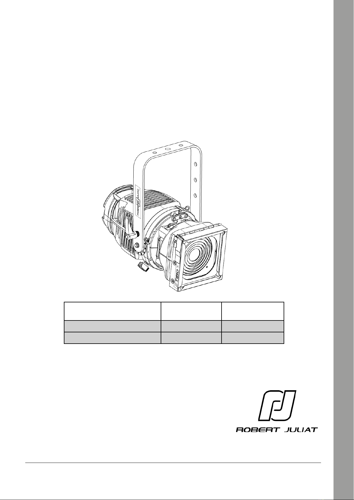
TIBO
Manual / Manuel
Reference Standard North American
Référence Standard Nord-Américain
300/500/650 W (GY 9.5) 505 505C
600 W (G 9.5) 515 515C
Robert Juliat S.A.S. 32, rue de Beaumont, F 60530 Fresnoy-en-Thelle - phone : +33 (0)3 44 26 51 89 - fax : +33 (0)3 44 26 90 79 - [email protected]
www.robertjuliat.com

Robert Juliat reserve the right to change or alter any of the items detailed on this page,
to increase or improve manufacturing techniques without prior notice.
Table of Contents
1 User’s instructions .............................................................................................................. 1
2 Presentation ........................................................................................................................ 2
2.1 Functions..................................................................................................................... 2
2.2 Identication label ..................................................................................................... 2
2.3 Accessories included .................................................................................................. 3
2.4 Optional accessories .................................................................................................. 3
3 Set-up ............................................................................................................................. 4
3.1 Mechanics ................................................................................................................... 4
3.1.1 Operating positions......................................................................................................... 4
3.1.2 Minimum distance between a ammable material and the lighting unit....... 4
3.1.3 Instructions for use........................................................................................................... 4
3.1.4 Hanging..............................................................................................................................5
3.1.5 Safety cable........................................................................................................................ 5
3.2 Electrical data............................................................................................................. 6
3.2.1 Lamp.................................................................................................................................... 6
3.2.2 Power Supply.....................................................................................................................7
3.3 Accessories .................................................................................................................. 8
3.3.1 Front lter holder..............................................................................................................8
3.3.2 Barndoors...........................................................................................................................8
4 Operation............................................................................................................................. 9
4.1 Light intensity ............................................................................................................. 9
4.1.1 Range................................................................................................................................... 9
4.1.2 Control................................................................................................................................. 9
4.2 Beam size adjustment................................................................................................ 9
4.2.1 Range................................................................................................................................... 9
4.2.2 Control...............................................................................................................................10
4.3 Orientation................................................................................................................10
4.3.1 Range.................................................................................................................................10
4.3.2 Control ............................................................................................................................11
4.4 Colour ........................................................................................................................11
4.5 Peak and Flat adjustment .......................................................................................12
4.5.1 Range.................................................................................................................................12
4.5.2 Control...............................................................................................................................12
4.6 Beam shaping (Barndoors) .....................................................................................13
4.6.1 Range.................................................................................................................................13
4.6.2 Control.............................................................................................................................13
5 Service ...........................................................................................................................14
5.1 Preventive maintenance..........................................................................................14
5.1.1 Frequency.........................................................................................................................14
5.1.2 General visual check......................................................................................................14
5.2 Analysis .....................................................................................................................14
5.3 Exploded view / Spare parts list..............................................................................14
6 Troubleshooting ...............................................................................................................14

EN
EN - 1 -
1 User’s instructions
GENERAL INSTRUCTIONS
1. Not for residential use.
2. These fixtures must only be serviced by a qualified technician.
3. In addition to the instructions indicated on this page, relevant health and safety requirements of the appropriate EU
Directives must be adhered to at all times.
4. This fixture is in compliance with section 17 – Lighting appliance for theatre stages, television, cinema and photograph
studios. Standards NF EN 60598-1 and NF EN 60598-2-17.
5. This fixture is rated as IP20, and is for indoor use only.
FIXTURE
6. Warning: disconnect from mains supply before servicing.
7. Ensure fixture is correctly mounted on an appropriate support.
8. Protection screens, lenses and filters must be replaced in the event of any damage, such as cracks or deep scratches,
since these might reduce performance.
9. When hung or flown the fixture must be secured by an additional hanging accessory (such as a safety cable or bond) of suitable
length.
10. Safety bonds or cables must be securely attached to the back of the fixture and be as short as possible, or rolled up as necessary,
to minimise travel distance should the fixture be dislodged.
11. Movable accessories (barn doors, spill rings etc.) must also be secured with a suitable safety cable or bond at the front of the
fixture.
12. The combined weight of both the fixture and the accessories must be considered when choosing the load-bearing
capability of safety cable or bond.
13. Do not open lighting fixture when the lamp is ignited.
14. Warning: Both lamp and lamp housing become hot during use. Allow fixture to cool before servicing
15. Do not tamper with design of fixture nor any of its safety features.
16. Tighten electrical mains cable connections regularly and replace with one of identical specification if damaged.
17. Use only with correct power supply.
VENTILATION
18. Keep well away from flammable material.
19. Not for outdoor use. Do not cover. Do not permit fixture to get wet.
20. To avoid overheating, do not obstruct air vents.
21. Ensure any cooling fans are in correct working order. If fans are not working, turn fixture off immediately and service as necessary.
LAMP
22. Check that the lamp voltage corresponds to the mains voltage used. Only use a lamp of type and voltage indicated on lamp
housing or packaging.
23. Replaced lamp if damaged or deformed by heat.
24. Ensure lamp is correctly fitted before use.
CLEANING
25. Clean all optical parts (lenses, lamps, etc.) with alcohol-based cleaner.
26. Regularly remove dust from mirror with a soft, clean cloth.
27. Clean all filters regularly.
PLEASE NOTE
These products have been built to conform to European standards relating to professional lighting equipment. Any modification
made to our products will void the manufacturers' warranty.

EN
EN - 2 -
2 Presentation
2.1 Functions
2.2 Identication label
Functions
Description
1. Peak/flat set-up
2. Handle
3. Hanging yoke
4. Tilt locking handle
5. Beam angle adjustment
6. Safety cable attachment point
7. Unit rotation locking button
8. Tilt index
9. Front slot locking system
10. Front slot for accessory and gel frame
11. Safety cable attachment point for
accessories
1. Serial number
2. Version

EN
EN - 3 -
2.3 Accessories included
2.4 Optional accessories
Reference Description
1 PF100M 138x138 mm metal filter holder
Reference Description
1 PF100M Barndoor 135 x 135 mm (without safety cable)
2 872 Doughty Twenty clamp with M10 screw/nut for Ø48 to 51mm
pipes – SWL: 20Kg - TÜV certified
3 878 25x6 hook clamp for 23mm screw for Ø35 to 50mm pipes – SWL:
11Kg max.
4 CS2 Safety cable Ø3 mm (length = 600mm) - SWL: 75 Kg
1
1
4
2
3
This manual suits for next models
1
Table of contents
Languages:
Other Robert Juliat Lantern manuals


Popular Lantern manuals by other brands


shada
shada 1000436 instruction manual

BEGA
BEGA 84 036 Instructions for use

BEGA
BEGA 33 596 Instructions for use

Dale Tiffany
Dale Tiffany GT701162 Assembly instructions

Wagan
Wagan Brite Nite Pop-Up USB Lantern user manual

Eaton
Eaton Crouse-Hinds Pauluhn DLLA M2 Series Installation & maintenance information