Robertshaw 571A Owner's manual

1
Avoid Catastrophic Failure
Protect your rotating or reciprocating
machinery, including pumps, motors, fans,
blowers, gear boxes, compressors, turbines
and other machinery from excessive vibration.
Vibration monitoring will alert you of
increasing machine vibration levels so
preventative maintenance can be scheduled
before catastrophic failures occur.
General Description
Robertshaw’s model 571A is a loop powered
(14 – 30 VDC) vibration transmitter that
provides a 4-20 mADC output proportionate
to vibration. The transmitter is available with
a variety of acceleration and velocity ranges.
This rugged (316L Stainless Steel, NEMA 4X,
IP68) compact unit provides continuous
monitoring of machine vibration for trending,
alarm and/or shutdown when used with a
PLC, computer, DCS, data logger or current
relays. When used with an approved barrier
the transmitter is intrinsically safe for use in
hazardous locations. Without a barrier the
transmitter is rated non-incendive.
Installation is simple and no calibration is
required. A 1/4-28 stud is provided for
mounting in a 1/4-28 tapped hole. The unit
has a 2 pin connector and mates with a
standard MIL-C-5015 2 socket connector with
splash-proof boot for a weatherproof, splash-
proof connection. Optional cable assemblies
are available in lengths of 16, 32, 64 and 112
feet.
Sales Manual Section 140
Product Specification Model 571A
Intrinsically Safe
Loop Powered Stud Mount
Vibration Transmitter
Cable Sold Separately
Features and Benefits:
• Two wire loop powered (14 – 30 VDC)
• 4 – 20 mADC output (isolated)
• Compact design, 1.12” diameter, 2.80”
height
• Corrosion resistant (316L Stainless
Steel)
• Certified Intrinsically Safe (with
barrier)
• Certified Non-Incendive (Division 2)
in the USA & Canada (without
barrier)
• NEMA 4X, IP68, hermetically sealed
enclosure
• ESD and EMI protection
• Overload protection
• Reverse wiring protection
• Available for either acceleration or
velocity measurement
• CE & ATEX Certified
• No Trim Pots required

2
ORDERING INFORMATION
AND MODEL NUMBERS
Order by model number in Table 1.
Table 1 - Measurement
MODEL NO. DESCRIPTION
571A-A Acceleration, 0 - 5 G peak
571A-B Acceleration, 0 - 10 G peak
571A-C Acceleration, 0 - 20 G peak
571A-D Velocity, 0 - 0.5 IPS peak
571A-E Velocity, 0 - 1 IPS peak
571A-F Velocity, 0 - 2 IPS peak
Accessory Items
PART NO. DESCRIPTION
086568A0016* Standard IP66 Cable - 16 foot,
2 conductor shielded cable,
MIL-C-5015 2 socket connector with
splash-proof boot.
086568A0032 Standard IP66 Cable - same as above
except 32 foot
086568A0064 Standard IP66 Cable - same as above
except 64 foot
086568A0112 Standard IP66 Cable - same as above
except 112 foot
086568B0016** IP68 Cable - 16 foot, 2 conductor
shielded cable, MIL-C-5015 2 socket
connector with splash-proof boot
086568B0032 IP68 Cable - same as above except 32
foot
086568B0064 IP68 Cable - same as above except 64
foot
086568B0112 IP68 Cable - same as above except
112 foot
435KB311 Mounting stud for 1/4-28 tapped hole
(supplied with transmitter)
435KB311-01 Mounting stud for 3/8-24 tapped hole
435KB311-02 Mounting stud for M8 X 1.25-6G
tapped hole
435KB311-03 Mounting stud for M6 X 1.00-6G
tapped hole
* 16 foot standard cable is a stock item.
For other cables allow 6-8 weeks delivery.
Cable accessory must be ordered separately.
** For submersible applications use IP68 cable.
SPECIFICATIONS
DYNAMIC
Output (±5% of span) ……………..……....… 4 – 20 mADC
Vibration Range ………………………..…..…… See Table 1
Frequency Response:
- 3 dB …..………………….….…... 2 Hz – 2 kHz
Repeatability ………………………………..………..... ±2%
Resonant Frequency, mounted, nominal ………..…… 28 kHz
Transverse Sensitivity, max. …………..…………..…….. 5%
ELECTRICAL
Power Requirements (Two wire loop power):
Voltage Source …………….....14 VDC – 30 VDC
Loop Resistance …….…………………….……….see page 4
Grounding …………………………………….. case isolated,
internally shielded
Protection ………………….……… reverse wiring, overload,
ESD & EMI
ENVIRONMENTAL
Temperature Range …….…..…-40°to 85°C (-40°to 185°F)
Vibration Limit ……………………………………250 g peak
Shock Limit ………………………………….….2,500 g peak
Electromagnetic Sensitivity, equiv. g …………... 10 µg/gauss
Sealing ………………………….. hermetic, NEMA 4X, IP68
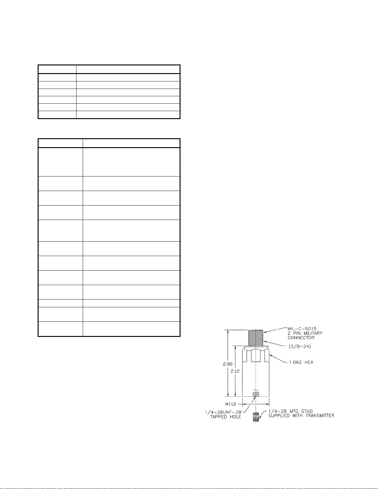
PHYSICAL
Sensing Element Design ………………….PZT ceramic/shear
Weight ……………………………………………..162 grams
Case Material ………………………….... 316L stainless steel
Case Rating ………………………………... IP68, NEMA 4X
Mounting ……………………………..…1/4 – 28 tapped hole
Supplied Accessories …………………..1/4-28 mounting stud
Output Connector ………………….….... MIL-C-5015, 2-pin
Pin A (white lead) ………………………. plus (+)
Pin B (black lead) ……………………….minus (-)
Cabling ……………………………… two conductor shielded
(see Accessory Items Table)
Torque Limit ………………………………... 30 in. lbs. Max.
Warranty ………………………………………………. 1 year

3
Mounting Instructions
The mounting point on the structure should be
faced to a diameter of 1.25 inches. For
measurements involving frequencies above 1 kHz,
the surface should be flat within 1 mil and have a
surface texture no greater than 32 micro-inches.
The tapped hole must be perpendicular to the
mounting surface and at least two threads deeper
than the stud. This will prevent a gap between the
transmitter and the mounting surface producing
optimum frequency response.
Proper screw torque on the mounting stud is also
required. Under-torquing the transmitter reduces
the stiffness of the coupling. Over-torquing can
cause permanent thread damage to the transmitter.
It is recommended that the 1/4-28 stud be torqued
to a value of 30 inch-pounds.
SURFACE 32 1.25″DIA MIN
FINISH
.004 A
.001
-A-
.35
.25
Before stud mounting the transmitter, a coupling
fluid should be applied to the mating surfaces.
The coupling fluid protects the mounting surface
and optimizes the frequency response by
increasing the coupling stiffness. Suggested
coupling fluids are machine oil or vacuum grease.
It is recommended that a thread adhesive such as
Loctite 222 be used.
Cable Routing and Electromagnetic
Interference
Walkie-talkies, power lines, or even electrical
sparks may cause signal interference. The
following guidelines will eliminate many
measurement errors due to electromagnetic
radiation and electrostatic discharge (ESD).
Assure that high quality, well shielded cables are
used. If cable splices are made, complete
shielding must be maintained.
Proper cable routing is imperative. Never run
transmitter cable alongside AC power lines; cables
must cross AC power lines at right angles. Where
possible, provide a separate grounded conduit to
enclose the transmitter cable. In addition, route
the cable away from radio transmission
equipment, motors/generators, and transformers.
Finally, avoid routing the cable through areas
prone to ESD. Even though transmitters are
protected against ESD failure, temporary
distortion signals may appear at the output.
Cable Grounding and Ground Loops
In order to provide proper shielding and prevent
ground loops, cable grounding should be
carefully considered.
For transmitters using two conductor shielded
cable, the power is carried on one lead and the
return on the other. The cable shield serves to
protect the signal from ESD and electromagnetic
interference (EMI). The shield should be
grounded at only one point.
Cable Anchoring
After mounting the transmitter, the cable should
be anchored to reduce stress at the cable
terminations. When securing the cable, leave
enough slack to allow free movement of the
transmitter.

4
CERTIFICATIONS
CSA Certified for the USA and Canada
Intrinsically Safe....................... Class I, Division 1,
Groups A, B, C & D; T3C
when connected as shown on
drawing 12641 (barrier required).
Non-Incendive .......................... Class I, Division 2,
Groups A, B, C & D
(barrier not required).
0081 II 1 G
LCIE 03 ATEX 6113X Certified for Europe
Intrinsically Safe................................. EEx ia IIC T3
when connected as shown on
drawing 12641 (barrier required).
Safety Barriers
Entity parameters
Groups .....................................A, B, C & D
Vmax or Ui...................................... 30 Vdc
Imax or Ii ........................................106 mA
Recommended Barriers................... MTL 706+,
MTL 787S+,
MTL 7087+,
MTL 7187+,
MTL 7787+,
STAHL 9001/51-280-091-14
Due to continued research and development, the manufacturer
reserves the right to amend these specifications without notice.
LOOP RESISTANCE
Maximum loop resistance can be calculated by:
V power – 14 V
RL(max) =
20 mA
Loop resistance is the sum of the wiring resistance and
the load resistance.
Typical
POWER SOURCE
VOLTAGE RL(max)
16 100 Ω
20 300 Ω
24 500 Ω
26 600 Ω
30 800 Ω
Reference: Robertshaw cable resistance is 40 Ωper
thousand feet.
Q-4169 (10/04) Printed in U.S.A.
Other Robertshaw Transmitter manuals