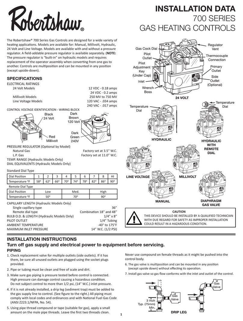
3
OPERATION
With the start Point Adjusting Nut (7) at the desired
setting, introduction of instrument pressure creates an
upward force against the Valve Seat Assembly (1). When
the instrument pressure exceeds the downward force of the
Start Spring (8), the Valve Seat Assembly (1) is forced
upward unseating the upper (larger) hemispherical surface
of Valve (2). This opens the passage between the Supply
and Output chambers allowing supply air to flow into the
output chamber and out to the Actuator Diaphragm
Chamber.
The motion of the Valve Seat Assembly (1) is also
transmitted to Pivot (3) acting against Arm (4). This arm
transmits the movement to Feedback Lever (5) which is
connected by a spring to the terminal control valve stem.
Through this linkage, motion of the control valve stem is
fed back to the Valve Seat Assembly (1).
Increasing output pressure moves the control valve stem
downward, increasing the spring force downward against
the Valve Seat Assembly (1).
Rotation of Lever (5) moves Pivot (6) along Arm (4)
thereby adjusting the throttling range of the control.
Therefore, the movement of the control valve stem is
proportional to the instrument pressure change and the
downward force transmitted to the Valve Seat Assembly
equals the upward force of the instrument pressure and both
surfaces of Valve (2) are seated.
Any reduction of the instrument pressure causes an
unbalance, allowing the valve seat assembly to move
downward, opening the lower surface of the Valve (2) and
exhausting Control Valve Diaphragm air pressure until the
control valve stem has moved upward a proportional
amount.
ADJUSTMENTS
Vary the instrument pressure over the range and turn the
throttling range adjusting screw until the desired throttling
range is achieved in stroking the valve.
Then, with the instrument pressure at the desired start
point, turn the start point adjusting nut (Figure 1) until the
valve just begins to move.
MAINTENANCE AND REPAIR
The design of the Model P2 makes routine maintenance
unnecessary.
It is recommended that no field maintenance be
attempted on the device other than replacement of the filter
beneath the supply air connection.
If repair becomes necessary, replace the unit with a new
or factory reconditioned unit.
Figure 3


