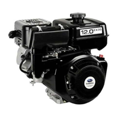
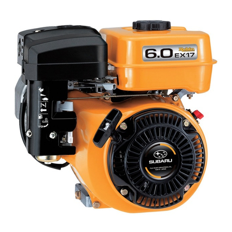
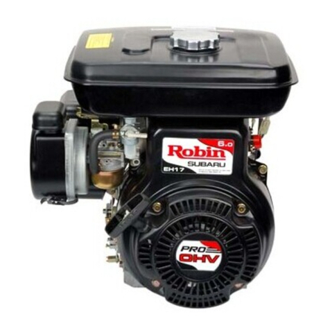
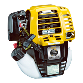
Robin EH11/W01-115 Operating instructions


GENERAL
INFORMATION
Wisconsin Robin
WO1-115,
150
and
210
engines
are of the four cycle type, inwhich each ofathefour
operations of suction, compression,expansion and
exhaust constitutes a complete stroke.This pro-
duces one power stroke for each
two
revolutionsof
the crankshaft.
These engines provide dependable service with
qualityandstrengthwherethey areneeded.
A
heavy
cast iron cylinder liner, forged steel crankshaft and
camshaft, forged alloy bearings andan aluminum
alloy connecting rod, alladd up to improved
durability.
MECHANICAL DECOMPRESSOR
Foreasy engine starting, a mechanical decom-
pressor is mountedon the camshaft to decreasethe
recoilpulley force. The decompressor opens the
exhaust valvebeforecompressionreachesthe max-
imum to reduce thecompression pressure,which in
turn decreases therecoil pulley force.
IGNITIONSYSTEM
A
pointless magneto ignitionsystem is standard on
these engines.Thissystem, referred to asT.I.C.
(Transistor Ignition Circuit), is completely free of
problemsassociated withbreakerpointtype ignition
systemssuch as start-up failuredueto dirty,burnt or
oxidized point surfaces, lowignitionefficiency
because
of
moisture, rough breaker point surface
and incorrecttimingresulting from worn me-
chanical parts.
A
Solid StateIgnition System is anavailable op-
tion.
LUBRICATION
An oilscraper
on
theconnectingrodcap splashesoil
in the crankcase on the rotating and sliding parts.
COOLING
Cooling is accomplished by a flow of air circulated
pastthe cylinder wallsandheadfinsfrom acombina-
tion fan-flywheel encased in a sheet metal shroud.
Air isdivided and directedby ducts and baffle plates
toinsureuniformcooling of all parts.
CARBURETOR
The engines are equipped witha horizontaldraft car-
buretor that has a float controlled fuel system. The
carburetorhas been carefully settoassuresatisfac-
torystart-up,acceleration,fuel consumption and out-
put performance.
A
fuel pump is standard on
WO1-115
and
WOl-150
carburetors only.The fuel pump improves engine
operation at a tilted angle.
GOVERNOR
A
centrifugal flyweightgovernor controls the engine
speedbyvarying the throttle opening
to
suitthe load
imposed uponthe engine.
REDUCTION GEAR
A
l/2
reduction gear is anava,ilable option on the
engines.
ROTATION
Rotationof the crankshaftisclockwise whenviewing
fromthe flywheel sideof theengine. Thisgivescoun-
terclockwise rotation at thepowertake-off endof the
crankshaft.
AIR
CLEANER
The engines are equipped with an oval air cleaner
with a sponge element.
A
cyclone type air cleaner
with semi-wet double elements are an available
option for the engines.
OIL
GRADE
CHART
Crankcase Capacity
E:;::
1.27
pts.
(0.60L)
WOl-2
10
I
1.37
OtS.
(0.65U
f
"Use
oilsclassified as Service
I
SE
or
SF
I
I
Seasons
or
Temperature
I
Gradeof
Oil
I
I
(+49'C
to
+4"a
I
Spring,
Summer
or
Autumn
+120"F
to
+40°F
1
SAE30
I
Winter
+40"F
to
+15"F
1
SAE2O
I
(+ST
to
-9X)
Below
+15"F
(-9°C)
SAEl
OW-30
i
W
1-1

IGNlTlC
Figure
1-1.
SectionalViews
of
Engine Models
WO1-115
and
WO1-150
,-
1-2

VALVE
ROCKER
ARM
I
Figure 1-2. Sectional
View
of
Engine
Models
WO1-115 and WO1-150
1-3

Figure
1-3.
SectionalView
of
Engine Model
21
0
I
14

Q
P
Figure
1-4.
Sectional
View
of
Engine Model
21
0
r
CAR3URETOR
1-5

SPECIFICATIONS
Model wo1-210WO1-150
WO1-115
Type
2.28 in.
(58
rnm)
Bore
Air-Cooled4-Cycle, Vertical Shaft, Single Cylinder, OverheadValve, Gasoline Engine
2.05 in.(52
mm)
1.81 in. (46
mm)
1.69 in.(43
rnrn)
Stroke
2.83 in.(72
mrn)
2.52 in. (64
mrn)
Displacement
Forced
Air
Cooling
Cooling System
Counterclockwise FacingPTO Shaft
Rotation
12.92 cu. in. (21
1
cc)9.02 cu. in. (147 cc)
6.93 cu. in.(1 13cc)
Lubrication
SAE
30,20
or
1
OW-30
See Oil Chart.
Lubricant
SplashingType
Carburetor
Regular Gasoline (Leadedor Unleaded)
Fuel
Horizontal Draft, FloatType
Fuel Consumption Ratio
(gr-HP-h) 230at continuous ratedoutput operation
Fuel Feed Gravity Type
Fuel Tankcapacity
1.1
1gal.
(4.2
L)
0..77 gal. (2.9
L)
0.55
gal. (2.1
L)
Reduction Ratio
'/2
-
'/2
-
'/2
-
Governor Centrifugal FlyweightType
IgnitionSystem
NGK
BPGES
or
CHAMPION
N9Y
Spark Plug
Pointless MagnetoType (Solid State Ignition)
LightCapacity (V-W)
I
12V
-
15W (available,
if
required)
Starting System Recoil Starter
Net
Dry
Weight
47.5
Ibs.
(21.5 kg)
46.4 lbs(21.0kg)
32.7 Ibs(l4.8kg)31.6 Ibs.(14.3
kg)
28.0 lbs.(12.7
kg)
26.9 Ibs(12.2kg)
Starting System Recoil Starter
Net
Dry
Weight
47.5
Ibs.
(21.5 kg)
46.4 lbs(21.0kg)
32.7 Ibs(l4.8kg)31.6 Ibs.(14.3
kg)
28.0 lbs.(12.7
kg)
26.9 Ibs(12.2kg)
Length
15.08 in.(383
rnm)
13.74 in. (349 mm)12.36 in.(31 4
mrn)
WidthDimensions
14.69 in.(373
rnm)
12.72
in.
(323
mm)
12.13 in. (308
rnrn)
Length
15.08 in.(383
rnm)
13.74 in. (349 mm)12.36 in.(31 4
mrn)
WidthDimensions
14.69 in.(373
rnm)
12.72
in.
(323
mm)
12.13 in. (308
rnrn)
Height 16.46 in. (41
8
mm)
12.95 in. (329
rnrn)
12.56 in. (31
9
mm)
1
-6

MAINTENANCE ANDSTORAGE
ENGINE MAINTENANCESCHEDULE
Q
ACAUTION: Failure tofollow thisschedule will seriouslydamagetheengine.
Daily
1
'
MAINTENANCE Every
I
or
8
hrs.
I
20
hrs.
Add fuel
to
tank.
Check oillevel.Add to
full mark.
Do
not overfill.
Clean air intake screen.
Clean cooling fins
if
needed.
0
Inspect unit for
loose hardware,lines,
or hoses.
Change crankcaseoil.
Inspect coolingsystem.
Removeblower housing
and scrape between
fins, around cylinder
head and from housing.
0
a
I
Cleanaircleaner.
I
I
Check and clean
Clean fuel filter andfuel
tank.
Clean contact and
breaker points.
Disassembleand clean
carburetor.
Removecarbon
from cylinderhead.
Weekly
I
Monthly or
I
Semi-annualSee Note
or
50
hrs.
100-200
hrs.
500-600
hrs. Below
*.
*
*
a
*
0
-*
I*
/.I
I*
1.
,
*Under severe environmental conditions these itemsmay need to be maintainedmore frequently.
Cleaning
Air
Cleaner
Remove air cleaner cover. Remove element from base.
Washelement in detergentandhotwater, then dry
thorou-ghly. Wipeall other components clean. Saturate
elementwithlightoil.Squeezefirmly to evenlydis-
tribute oil andremoveanyexcess.
Service daily
if
engineis operated in very dusty and dry
grassconditions.
A
cloggedaircleanerwillresult in
highfuelconsumption,
loss
of
powerandexcessive
carbonbuild-up inthe combustionchamber.
i
ENGINE STORAGE
Ifnot properlyprotected,temperatureandhumidity
changescan causecorrosionof pistonrings,cylinder
walls and bearing surfacesina stored engine. For max-
imum protection,prepare the engineforstorageas
follows:
1.
Runthe engine untilit reaches operating tempera-
ture.Stop the engineanddrain the oil from
crankcasewhileengineisstillwarm.
2-1

2.
Drain fuel lines, carburetor, fueltank and fuel
pump
(if
equipped), to prevent lead and gum
sediment from.interfering with future operation.
Gasoline fumes from gradual evaporation are a
dangerous fire hazard.
3.
To
protectthe internal components and keep
them from rusting and sticking, a half and half
mixture of keroseneand good engine oil(same
grade as used in the engine crankcase) should
be injectedinto the carburetorair intake.
Do
this
while the engine
is
warm and running at mod-
eratespeed. Useenoughof the mixture(about
l/4
pint)
so
that a heavy, bluish smoke appearsat
theexhaust. This“fogging” operation will leavea
coating of oil on the parts, protectingthem from
the atmosphere.
4.
Turn thestarting pulley by hand andleave it
where the resistance is the heaviest.
5.
Tape
or
seal
off
air cleaner andexhaust
openings for the duration
of
the storage
period.
6.
Remove all dirt and chaff from the cooling
fins.
7.
Clean the engine outside with an oiled cloth.
8.
It
is highly recommended that machines be
stored insidea buildingthrough thewinter.
If
this
is not possible, the engine should be protected
from snow and ice by a suitable covering.
NOTE: Before adding newcrankcase oil the next
season, drain engine
of
condensationwhich
may haveaccumulated in thecrankcasedur-
ing the storage period. Fill crankcase with
good quality oil before starting engine
(see‘SPECIFICATIONS).
2-2

B
The three primerequirementsnecessary for starting and maintaining satisfactoryoperation
of
gasoline engines
are:
1.
A
proper fuel mixture in the cylinder
2.
Goodcompression in thecylinder.
3.
Good spark at the correct time, to ignite the mixture.
There are otherfactors which contributeto hard starting; suchas too heavy a loadfor the engineto turn over at
low starting speed,long exhaust pipewith high back pressure, etc. These conditions mayaffect starting, but do
not necessarily mean the engine is improperly adjusted.
The most common symptoms of engine problems are given here, followed by the probable causes.
ENGINE
WILL
NOT
START, ORHARD
TO
START
Electrical System Problems Caused By:
Weak or dead battery.
Poor groundconnection.
Defective starter.
i
FuelSystemProblemsCausedBy:
Fuel tank empty. Improper or contaminated
fuel.
Carburetor not chokedenough (cold en-
gine).
Low
cranking
speed.
Restricted cooling air circulation.
Loose fittings or defective fuel lines.
Carburetor needle valve held open bydirt or
gum.
Defective speed control or governor.
Fuel or oil leaks.
Ignition System Problems Caused By:
Loose
or
corroded electrical connections.
Ignition wires disconnected or broken.
Damaged or loose ignition module.
Faulty ignition coil.
Spark plug cable wet or broken.
Spark plug wet or dirty.
Spark ptug point gap incorrect.
CompressionSystem ProblemsCausedBy:
Lack of lubrication on moving parts due to
long storage.
Incorrect oil grade or
low
oil
level.
Loose or broken spark plug.
Damagedhead gasketorloose cylinder
head.
Incorrecttappet clearance.
Valve stuck open due to carbon or gum on
valve stem.
Defective or incorrectly adjustedvalve com-
ponents.
Worn valve guides, piston or rings.
Scored or worn cylinder walls.
3-1

ENGINE
MISFIRES
Incorrect spark plug gap.
Ignitioncable leaking.
Weak spark
Ignitionwires loose.
Water or dirtingasoline.
Insufficient compression.
ENGINE
STOPS
Fueltank empty.
Water, dirt, gum, etc.ingasoline.
Vapor lock(gasolineevaporatinginfuel lines
dueto excessive heataround engine).
Vapor lock in fuellinesor carburetor
dueto incorrectfuel.
Enginescored
or
stuck dueto lack of oil.
Air vent hole inthefuel tank cap plugged.
Magneto or ignition coilfaulty.
ENGINEOVERHEATS
Crankcaseoil level
low.
Sparktiming incorrect.
Low
grade gasoline used.
Engineoverloaded.
Cooling air restrictedfrom dirt
or
debris.
Engine operated in confined space where cool-
ingair is continually recirculated.
Restricted exhaust.
Heavy load
at
low enginespeed.
0
ENGINE KNOCKS
Low quality gasoline.
Engine operating under heavy load at
low
speed.
Carbon or lead deposits in cylinder head
or
on piston.
Sparktiming incorrect.
Worn
or
damagedconnecting rodbearing.
Worn or damagedpiston pin.
ENGINE BACKFIRES THROUGH
CARBURETOR
Wateror dirt in gasoline, or poor grade
gasoline.
Intakevalve stuck
Valvesoverheated,
or
particles in combustion
chamber.
Enginecold.
ENGINESURGES
OR
GALLOPS
Carburetorflooded.
Governor rod installed wrong,orgovernor out
of adjustment.
Highspeedjet
in
carburetor partially
restricted.
/?
3-2

IGNITION
The standard ignitionsystem for engines
WO1-115,
150
and
210
is a magneto ignition system called
T.I.C. (Transistor Ignition Circuit).T.I.C. consists
of
an
ignition coil witha built-in transistor mountedon
the flywheel.
For initialexcitation,aSolidStateIgnition is anavail-
able option for these engines.
SYSTEM
OPERATION
Figures
4-1
and
4-2
Revolution
of
the flywheel generates electricity on
the primary side
of
the ignition coil, and theelectric
SYSTEM
current
(A)
runs.
(A)
makesthe powertransistor
"ON"
and the electric current
(B)
passes.
The flywheel goes roundfurther, and at the time
of
ignition the electric current (C) runs,thenthe electric
current
(D)
runs
to
the signaltransistor, by which the
electric current
(B),
passing through the power tran-
sistor,is abruptly cut;and as a result, thehigh
voltage electricity
is
generated onthe secondary
side
of
the ignition coiland itsparksat the plug.
Figure
4-2
illustrates theenginewiring diagram.
-
RESISTOR
f
IGNITION
COIL
Figure
4-1.
STOP
BUlTON
IGNITIONCOILCONNECTOR
-r
SPARK
PLUGBLACK
mrr
(OPTION)
EXCITER
COIL
(
I
I
l""1
I
i
FLYWHEEL
Figure
4-2.
4-
1

SYSTEM
CHECKS
Inthe event of amalfunction
of
the ignition
system:
Check the magneto fordefects.
Check
the
high voltagewire for damage or
if
shorted.
Faulty spark plug, caused by moisture, dirt, broken
insulation
or
incorrect plug gap.
CHECK
SPARK
If
difficulty is experiencedin starting the engineor
if
engine misses firing, check the strength of the igni-
tion sparkRemove the sparkplug. Withthe ignition
cable connected to it, lay the spark plug on a con-
venient metal part
of
the engine
so
that the gap can
be observedas yourotatethecrankshaft several
times using the recoil starter.
If
a good strongspark
occurs,the ignition system can be eliminatedas the
source
of
trouble.
CHECK FLYWHEEL
Check that the external magnet, mounted
on
the
flywheel isin
good
condition.
CHECK FLYWHEEL
AIR
GAP
Figure
4-3
Use a non-metallic feeler gauge to measure the air
gap between the flywheel andthe ignition coil.
Loosen theignition coil hold down screws
to
adjust
the gap to specifications (see ‘SPECIFICATIONS’).
FEELER
GAUG
COIL
I
Figure
4-3.
4-2

FUEL
SYSTEM
AND
GOVERNOR
FUEL
SYSTEM
Alwaysuse a high quality brand of leaded or
unleadedgasoline free from dirt and water.Some
poorer grades of gasolinecontain gum which
depositsonvalvestems, piston rings,and inthe
varioussmallpassagesin the carburetor. Thiscan
cause serious engine operating problems.
Use
gasoline with an octane rating of atleast
86.
Fuelwith a
low
octaneratingwillcause detonation. If
operation
is
continued underthis condition, severe
damage will result to the engine.TeledyneTotal
Power recommendsfuels with no more than
10
per-
cent alcohol content.
GOVERNOR
OPERATION
The governor is mountedon the governor gearinthe
crankcase cover.
As
the engine speedincreases,the
centrifugal force in the flyweights acts against the
governor spring and closesthecarburetor throttleto
a point where the engine speedwill be maintained
practically constant under varying load conditions.
GOVERNOR ADJUSTMENT
Figures
5-1
-
5-4
IMPORTANT:This procedureshould be
necessary only
if
the governor lever was
loosened or removed.
Forcorrect carburetorthrottle opening and governor
regulation, the governor lever must be properly
adjusted.
1. Install governorrod andgovernor spring on
throttle lever and governorlever. Mount gover-
norlever on governorshaft. for models
WO1-
1
15 andWO1-150, refer to Figure 5-1.
If
removed,installspeedcontrol leveroncylinder
head.
\
SPRY
>
GOVERN~R
ROD
SPRING
:I-
/
/
\
GOVERNOR
LEVER
HIGH
SPEED
CONTROL
LEVER
SPEED
GOV~RNORSPRING
GOVERNOR ROD HOOKING
POSITION
2.
Hook
governor spring from speed control lever
to governor lever.FormodelsWO1-115 and
WO1-150,
refer to Figure
5-2.
Fo’r
model
WO1-2
10,
refer to Figure
5-3.
The
governor spring may be hooked to a different
position according
to
generator specifications.
3.
Turn control lever clockwise(toward“High
Speed”) until throttlevalve in carburetor is fully
open. Hold lever in this position.
IMPORTANT:Check that governor lever clamp
screw is loose
so
governor shaft can be turned
independently oflever.
-
Figure
5-3.
60Hz
2-6
50Hz
4-5
Figure
5-1.
5-1

4.
RefertoFigure
5-4.
Insertascrewdriver inslot at
end of governor shaft. Turn clockwise as far as
shaft can be turned. Tighten governor lever
clampscrew.
1
GOVERNOR
SHAFT
GOVERNOR
LEVER
TIGHTENING BOLT
:igure
5-4.
GOVERNOR SPRINGAND
GENERATOR SPECIFICATIONS
Figure
5-5
I'
For engines WO1-115 and WO1-150, there are
two
types of governor springs, one for
50
Hz
and the
other
60
Hz.
The locations for either spring are listed
in Figure
5-5.
The differance between the springs: Dimension
A
is
longer.
60Hz
(STD)
50Hz
I
WO1-115
4-A
WO1-150
4-A
WO1-115
4-A
WO1-150
3-A
L
Figure
5-5.
/"
5-2

CARBURETOR
B
FUEL
PUMP
Figure
6-1
The fuel pumpconveysthepulsating pressureinthe
crankcase to thediaphragmchamber to vibrate the
diaphragm and changethevolume, thereby drawing
and discharging thefuel. Thediaphragmsuction and
discharge passageshaveonevalve eachwhich
allows fuelflow inone direction only,thus preventing
reverse fuel flow.
FLOAT
SYSTEM
Figures
6-1
and
6-2
The fuel bowl (float chamber)
is
mounted directly
beneaththecarburetorbody. Fuel fromthefuel tank
is suppliedto thefuel bowl through the fuelinlet and
needlevalve. The fuel in thebowl is maintainedat a
predetermined level by the float through its control
of
the needle valve.The needle valve openingis
regulated by the speed andload(fueldemand)
of
the
engine.
Figure
6-1.
Sectional Views
of
Carburetor
Models
WO1-115
and
WO1-150
i
6-
1

IDLE
SYSTEM
Figures 6-1
and
6-2
The idle system supplies fuel to the engine during
idleand low speed operation. Fuel isfedthrough the
mainjet to the idlejet.The fuel,measuredbythe idle
jet, is then mixed with air from the idle air jet. This
supply of fuel and air is discharged totheengine
through the idle outlet. At high speeds, the throttle
valve opens to allow the fuel-air mixture to be dis-
charged from both the idle outlet and by-pass
MAIN
(High
Speed)
SYSTEM
Figures 6-1
and
6-2
The mainsystemcontrolsthe air-fuel mixture during
r
medium and high speed operation. Fuel flows from
thefuel bowl,through themainjet and into themain
nozzle. Here the fuel is mixedwith air coming from
themainairjet andadmittedthroughthe bleedholes
of
the main nozzle.The mixture is discharged
through the top
of
the main nozzleas atomized fuel
where it mixes with intake air
to
become the
holes. optimum air-fuel mixture supplied to the engine.
BY-PASS
HOLES
Figure
6-2.
Sectional Views
of
Carburetor
Model
WO1-210
6-2

CHOKE
SYSTEM
Figures
6-1
and
6-2
The chokesystem providesa richfuel-air mixture for
cold weather starting.
When the chokevalve is closed,a
low
pressurearea
(vacuum)existsatthemainnozzle.
A
rush
of
fuelwith
relatively small amounts
of
air is obtained from the
main nozzle as the engine iscranked for starting.
Even with a cold engine, thisextrarich mixture
makes starting easy.
DISASSEMBLY AND REASSEMBLY
Figures
6-3
-
6-5
Besides mechanical failures, most troubles are
attributed to an incorrect mixing ratio.Themost
common causes of incorrect fuel-air mixtures are
clogged jets, restricted air and fuel passages,and
variations in the fuel level. Inorder to obtain the full
performance
of
the carburetor, the air cleaner and
carburetor must be clean
so
that air and fuel flow
without restriction. Usinggood quality,fresh, leaded
or unleaded gasoline will help keep the car-
buretor clean.
D
SPRING
13
U
r\
I
"IDLE JET
THROI~LE
SHAFT
CARBURETOR
BODY FLOAT PIN
~~
NOZZLE
4
>
NEEDLEVALVE
e
MAIN JET
FLOAT
&
FLOAT BOWL
igure
6-3.
Models
WO1-115
and
WO1-150
CHOKE
VALVE
@a-
\
SHAFT
CARBURETOR
BODY
:igure
6-4.
Model
WO1-210
Cleaning
Thoroughly clean all metal parts in a good quality
carburetor cleaner and rinse in cleaning solvent.
Blowout all passages in throttle body and fuel bowl
with reduced air pressure. Check that all carbon
deposits have been removedfrom throttle bore and
idle discharge holes. Reverse the
flow
of
com-
pressed air through all passages to insure the
removal
of
all dirt. NEVER
USE
A
DRILL OR WIRE
TO
CLEANOUTJETS OR IDLE HOLES.
Throttle System
Figures
6-3
and
6-4
1.
Remove screws to remove throttle valve and
throttle shaft from carburetor body. Use care to
avoid damaging parts.
2.
Remove throttle stop screw and spring.
6-3

Choke System
Figures
6-3
and
6-4
1.
Removescrews to remove choke valve and
choke shaft.Usecare to avoid damaging
parts.
2.
During reassembly, install with cut-out on valve
facing mainair jet.
Idle
System
Figures
6-3
and 6-4
1.
Remove idle jet.Use care to avoid damaging
parts.
NOTE: Idlejet is included in repair kit.
2.
During reassembly, tightenidle jet securely to
prevent fuel leakage.
Main
Fuel System
Figures
6-3
and 6-4
1.
Drain remainingfuel in fuel bowl into a suitable
container. Remove bowl and gasket.
2.
Removemain jet from carburetor body.
NOTE: Main jet is included in repair kit.
3.
During reassembly,tighten main jet securely to
prevent fuel mixture from becoming too rich.
Install fuel bowland new gasket. Torquescrew to
specifications (see 'SPECIFICATIONS').
Float System
Figures
6-3
and 6-4
1.
Removefloatpin, float and needle valve.
NOTE: Float pin isflattened atone end. Useasmall
drift punch and tap on float pin round end
to remove.
r
2.
Inspect float. Replace
if
dented, contains fuel, or
if
float
axle
bearing and tab contactingneedle
valve are worn excessively.
NOTE: Special service needle valve is included in
repair kit.
Inspect needle valve. Replace
if
damaged orworn.
3.
Duringreassembly,adjustfloat setting.Withfloat
chamber bowl removed, place carburetor body
on end. Float surface must be parallel to car-
buretor body. Toadjust float surface bend tab.
The tab (float lever) should just contact the fuel
needle valve.
Install float bowl using a new gasket. Torque to
specifications (see 'SPECIFICATIONS).
Fuel Pump
Figure
6-5
1.
Remove screws to remove fuel pump from car-
buretor. Use care not to lose 0-Ring.
2.
Removescrews
to
separatefuel pump. Usecare
to avoid damaging parts.
3.
During reassembly, keep the fuel pump free of
foreign matter.
"
FUEL
PUMP BODY
O-RING
DIAPHRAGM
MEMBRANE
GASKET PRIMER CAP
Figure
6-5.
,."
64

STARTING
SYSTEM
RECOIL STARTER
DisassemblyandReassembly
Figures
7-1
-
7-10
A
WARNING:
A
loaded power spring operates
under great pressure.
To
avoid personalinjury,
use care to keep power spring in housing.
DO
NOTremove spring unless for replacement.
1.
Refer to Figure
7-1.
Pull starter knobout from
housingabout
16
in.
(40
cm). Hold housing and
reel to prevent reel fromrewinding.
NoTCH
Figure
7-1.
2.
Pull out rope to the inside
of
recoil starter and
press rope into notchon reel. Releasereel to let
spring mechanism slowly unwind.
3.
Refer to Figures
7-2
and
7-3.
Remove return
'
spring, friction spring or plate andratchets.
4.
Referto Figure
7-4.
Slowly lift reel,turning lightly
left to right, from support shaft in housing.
Inspect rope. Replace
if
damaged orworn.
CAUTION:
Use rope of same lengthand
Refer to Figure
7-5.
Install new rope in handle.
Tie knotas illustrated about
1
%
in.
(35
mm) from
end. Pull knot tight and fit into top ofhandle.
Refer to Figure
7-6.
Insert otherend of rope
throughhousingguidebushingandthrough
hole in reel groove. Pull ropethrough cavity
opening. Make knot asillustrated about
1
in.
(25
mm)fromend.Fit knot into cavity.
A
diameter as originally furnished.
,PLATE
FRICTION
RETURN
SPRING
6
QT=
RATCH ET
Figure
7-2.
Models
WO1-115
and
WO1-150
U-SNAP RING
THRUST WASHER
FRICTION
SPRING
COVER
%
'
/FRICTION SPRING
RATCHETS
Figure
7-3.
Model
WO1-210
7-1
This manual suits for next models
2
Table of contents
Other Robin Engine manuals

Robin
Robin EY35 User manual

Robin
Robin Subaru EY15-3D User manual

Robin
Robin EH12-2D User manual

Robin
Robin EH12-2D User manual

Robin
Robin EC03ER User manual

Robin
Robin EHO9-2D User manual

Robin
Robin EH12-2D User manual

Robin
Robin EH36BS User manual

Robin
Robin PKX201T User manual

Robin
Robin EH18V OHV User manual