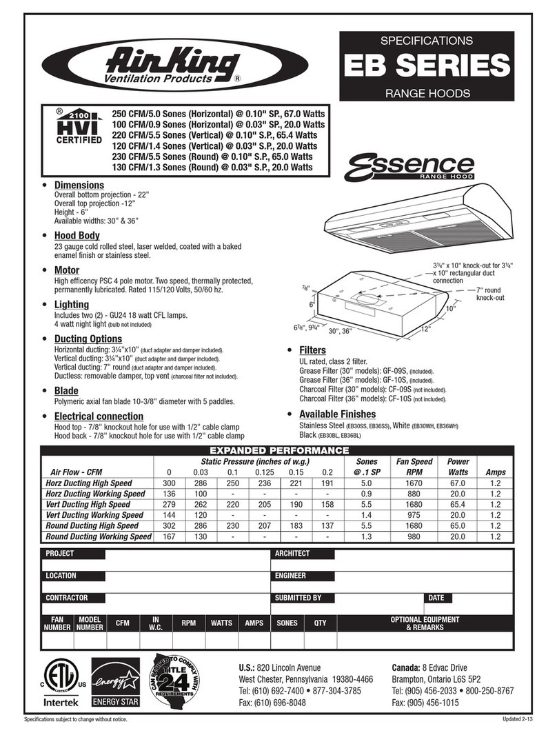
Robin ESPACE Manual

NOTICE D’UTILISATION ET D’INSTALLATION
DIRECTIONS FOR USE AND INSTRUCTIONS FOR INSTALLATION
ESPACE
CENTRALE

FSOMMAIRE
1CONSEILS D’UTILISATIONS
ENTRETIEN
GARANTIE ET
SERVICE APRÈS-VENTE
2REMARQUES
CONSEILS D’INSTALLATIONS
RACCORDEMENT ÉLECTRIQUE
3POSE DE L’APPAREIL
FONCTIONNEMENT
GB CONTENTS
4HINTS FOR USE
MAINTENANCE
GUARANTEE AND
AFTER-SALES-SERVICES
5REMARKS
INSTALLATION ADVICE
ELECTRICAL WIRING
6FITTING THE APPLIANCE
OPERATION

1
1CONSEILS D’UTILISATION.
•Pour obtenir une efficacité maximum d’absorption des fumées ou des vapeurs, faire
fonctionner l’appareil avant et après la cuisson des aliments; pour les préparations déga-
geant peu de vapeur, utiliser de préférence la petite vitesse.
•IMPORTANT . NE JAMAIS FLAMBER DE METS AU DESSOUS DE L’APPAREIL
Ne laissez jamais de flammes libres sous la hotte en fonctionnement.
Eteindre la flamme ou la réduire au minimum pour de courte période et sous surveillance.
•Si vous effectuez des fritures, c’est avec une surveillance permanente : l’huile sur-
chauffée pourrait s’enflammer.
2ENTRETIEN.
Déconnecter le câble d’alimentation pour toute intervention électrique.
L’appareil a été conçu pour faciliter au maximum les opérations d’entretien, synonyme de
bon fonctionnement et rendement de l’appareil dans le temps.
•Nettoyage des filtres métalliques.
Il est indispensable de procéder à un NETTOYAGE PÉRIODIQUE de ces filtres à la main
(avec un détergent liquide à l’eau tiède et rinçage) ou au lave- vaisselle avec une fré-
quence de l’intensité d’utilisation pour éviter le risque d’inflammation.
•Carrosserie.
Nettoyer régulièrement celle-ci en utilisant des produits détergents, non abrasifs et une
éponge légèrement humide. N’utilisez jamais d’éponges ou de chiffons trempés
N’introduisez aucun objet, ni les mains dans l’ouverture servant à l’évacuation de l’air
•Conduit d’évacuation.
Vérifier tous les 6 mois le bon écoulement de l’air vicié.
Observer les prescriptions réglementaires locales concernant l’évacuation de l’air vicié.
•Éclairage. Avant toute intervention sur l’appareil, mettre l’interrupteur d’allumage
des lampes en position éteinte.
- Modèle électrique Type de lampe: E 14 , 220-240 V, 40 W.
- Modèle électronique sans Transformateur ou convertisseur : GU 10 Halogène, 50 W -
220 - 240 V, ø 50, 50° d’ouverture.
- Modèle électronique équipé d'un transformateur ou d'un convertisseur : GX 5.3 Halogène
Ne pas dépasser la puissance prescrite et ne pas changer de type de lampe
3GARANTIE ET SERVICE APRÈS-VENTE.
•En cas d’anomalie de fonctionnement, prévenez votre installateur qui devra vérifier
l’appareil et son raccordement.
•Dans le cas où le câble viendrait à être endommagé, celui-ci ne peut être remplacé
que par un atelier de réparation reconnu par le fabricant, car des outils spéciaux sont
nécessaires.
•Débrancher complètement l’appareil.
•Exigez toujours l’utilisation de pièces de rechange d’origine. La non observation de
cette prescription peut compromettre la sécurité de l’appareil.
•Lors de la commande de pièces détachées, rappeler le numéro de l’appareil inscrit sur
la plaque signalétique.
F
20 W - 12 V, ø 50, 36° d'ouverture.

2
•Seule la facture d’achat de l’appareil fera foi pour l’application de la garantie contrac-
tuelle.
Cette garantie ne couvre pas :
- L’éclairage : lampes incandescentes, halogènes ...
- Les filtres.
Ceux-ci étant considérés comme des consommables.
4REMARQUES.
Nos appareils sont conformes aux normes harmonisées CEI 335 et aux directives euro-
péennes basse tension 73/23 et compatibilité électromagnétique 89/336.
5CONSEILS D’INSTALLATION.
•Pour un fonctionnement idéal, nous vous conseillons une plage de hauteur de pose
qui se situe de 0,65 m à 0,70 m au-dessus du plan de cuisson. Toutefois, il est formelle-
ment interdit d’installer toute hotte ou groupe d’aspiration à une distance inférieure à
0,65 m du plan de travail (risque d’inflammation des filtres). La fumée doit monter naturel-
lement vers la zone de captation (attention aux courants d’air qui créent des turbulences).
•Respecter le diamètre de sortie de l’appareil : la hotte ne doit en aucun cas être
raccordée à un conduit de ventilation mécanique contrôlée (V.M.C.).
•Lorsqu’on évacue l’air vicié dans un conduit d’évacuation, veiller à ce que celui-ci ne
soit pas déjà exploité à véhiculer des gaz ou fumées provenant d’appareils alimentés par
une énergie autre qu’électrique.
•Positionner le plan de cuisson au plus près de l’évacuation et éviter la formation de
coudes sur la gaine, afin de réduire au maximum les pertes de charges.
•Dans tous les cas d’installation, veiller au bon renouvellement d’air de la cuisine.
Penser à effectuer une ou des entrées d’air par une grille de section égale ou supérieure
au diamètre du tuyau d’évacuation, afin de ne pas mettre la cuisine en dépression.
•Prévoir une aération suffisante lorsqu’un appareil de cuisson ou autre utilise simulta-
nément l’air ambiant de la pièce où est installée la hotte.
•La dépression maximum crée dans la pièce doit être inférieur à 0.04 mbar, ce qui
évite un retour de gaz de combustion.
•L’appareil doit être positionné de telle façon que la fiche d’alimentation soit accessible.
6RACCORDEMENT ÉLECTRIQUE.
•La hotte est équipée d’un cordon d’alimentation de type HO5VVF 3 x 0,75 mm² com-
portant une fiche normalisée 10/16 A avec système de mise à la terre.
Mode de protection : classe 1.
Tension d’alimentation : 220-240 V mono - 50/60 Hz.
Vérifier que la tension du secteur est identique aux valeurs indiquées sur la plaque signa-
létique à l’intérieur de la hotte
•Si la hotte est raccordée directement sur le réseau sans sa fiche, un interrupteur
omnipolaire avec une ouverture de contact de 3 mm doit être installé avant la hotte. Le fil
de terre (Jaune / vert) ne doit pas être interrompu par cet interrupteur.
F

3
7POSE DE L’APPAREIL.
Montage et raccordement doivent être réalisés par un installateur* qualifié.
(*) Le non-respect de cette condition entraîne la suppression de la garantie du cons-
tructeur et tout recours en cas d’accident.
a) Enlever les vis du conduit.
Enlever les vis TH 5 x 10 qui fixent la boîte moteur sur le corps.
Débrancher le connecteur 6 voies.
b) Régler le support de hotte sur la boîte moteur à la hauteur désirée. Votre hotte est
réglable en hauteur par tranche de 50 mm ; les 8 vis 5 x 10 T. Hexagonale se logent
dans les trous oblongs permettant une mise à l’aplomb. (figure n° 1a pour le modèle
1200, figure n° 1b pour le modèle 900).
c) Percer le plafond à l’endroit de la pose, dont un trou de Ø 40 qui permet le passage de
l’alimentation, suivant la figure n° 2a pour un modèle 1200, suivant la figure n° 2b pour
un modèle 900.Si le plafond est en béton, employer 4 chevilles en fonte pour Ø 10,
exclure les chevilles en plastique.
Si celui-ci vous semble de solidité douteuse, n’hésitez pas à le renforcer dans les com-
bles (fig. 3).Une pastille de couleur sur la boîte moteur définit l’orientation des comman-
des.
d) Fixer solidement le support de hotte à l’aide de 4 tiges filetées Ø 10 mm, passer le tuyau
flexible et le raccorder ; remonter le conduit et le fixer à l’aide de ses vis.
e) Prendre en main les vis 5 x 10 T. Hexagonale.
f) A 2 personnes, saisir la hotte et l’emboîter sur le conduit. Fixer par les 4 vis de l’intérieur
de la hotte (figure n° 4).
Brancher le connecteur 6 voies à l’intérieur de la boîte moteur.
8FONCTIONNEMENT
tableau de commande
Touche :I - petite vitesse
Touche :II -moyenne vitesse
Touche :III - vitesse intensive
Touche :lumière
F

4
1HINTS FOR USE.
•To ensure maximum absorption of smoke or smells, turn the appliance on before and
after the food is cooked : for simmering and dishes which let off only a little steam, use the
low speed setting.
•IMPORTANT : NEVER FLAME A DISH UNDER THE APPLIANCE.
When using a gas hob in conjunction with this cooker hood never leave the burners of the
hob uncovered while the hood is in use or when the pans have been removed.
Switch of the gas before removing the pan, or for just short periods and never leave the
hob unattended.
•Never leave frying pans unattended during use as overheated fat and oil may catch fire.
2MAINTENANCE.
Disconnect the power cable before carrying out any electrical work.
The appliance has been designed to make cleaning as easy as possible. This leads to
more efficiency and a longer useful life.
•Removal of the filters.
These filters must be CLEANED REGULARLY , more regularly if required according to
use. They must be cleaned by hand (with liquid detergent in warm water and rinsed) or in
as dishwasher. These measures reduce the risk of fire.
•Casing.
Do not use wet clothes or sponges to clean the surface of the cooker hood.
Only use mild household detergents and soft damp clothes.
Do no insert hands or any other objects into the air outlet
•Extraction tube.
Check every 6 months that the dirty air is being extracted correctly. Comply with local
rules and regulations with regard to the extraction of vitiated air.
•Lighting :Before carrying out any work on the appliance, switch off the light.
- Electronic model equipped with transformer or converter: Halogen GX 5.3, 20 W - 12 V,
Ø 50 closed, 36° bundle opening.
- Electric model Typ of lamp : E 14 , 220-240 V, 40 W
Do not exceed this power and do not change the type of lamp.
3GUANRANTIE ANDAFTER-SALES SERVICE.
•In the event of any malfunction or anomaly, notify your fitter who will have to check the
appliance and its connection.
•In the event of a damage of the cable, this one can only be replaced by a repair shop
recognised by the manufacturer because special tools are necessary.
•Disconnect the hood from the mains supply.
•Ask for genuine spare parts.Should these warning fail to be observed it could affect the
safety of your cooker hood.
•When ordering spare parts, mention the number of the appliance written on the identi-
fication plate
GB
- Electronic model without transformer or converter: Halogen GU 10 , 50W - 220-240 V ,
Ø 50 closed, 50° bundle opening.

5
•On the strengh of the purchase invoice of the appliance only, the contractuel guaran-
tee could be applied.
This Guarantee doesn’t cover :
- The lighting : classic and halogen lighting...
- The filters.
These ones considered to be consummable
4REMARKS.
Our apparatus conform to harmonised standards CEI 335 and to the European directives
on low voltage 72/23 and electromagnetic compatibility 89/336.
5INSTALLATION ADVICE.
•Comply with the minimum and maximum height limits. To ensure perfect operation, we
advise that the appliance be placed at any height ranging from 0,65 m to 0,70 m above the
cooking surface. Nonetheless, it is strictly forbidden to install any cooker hood or extrac-
tor unit at a distance of less than 0,65 mfrom the worktop (the filters run the risk of
catching fire). The smoke must be allowed rise of itself towards the extraction area (be-
ware of draughts which create turbulence).
•Observe the specifications with regard to the diameter of the outlet for this appliance :
the cooker hood must under no circumstances be connected to a mechanically con-
trolled ventilation tube.
•Exhaust air should not be discharged into any chimney or flue which may carry com-
bustion products from other sources. Exhaust air should not be discharged into a wall
cavity, unless the cavity is designed for that purpose.
•Place the cooking surface as close as possible to the extractor and avoid causing
bends to be formed in the flue.
•In all types of installation, ensure that the air is being renewed in the kitchen. Remember
that one of the air inlets must have a cover grill of which the cross-section is at least as large,
if not larger, than the diameterof the extractor tube, thus avoiding a rarefaction of the air.
•Ensure adequate ventilation if the cooking appliance or any other appliance is at the
same time using the ambient air in the room where the cooker hood is fitted.
•When the cooker hood is used in conjunction with other appliances supplied with en-
ergy other than electricity, the negative pressure in the room must not exceed 0.04 mbar in
order to avoid a return of the fumes from combustion.
•The appliance must positioned so that the plug is accessible.
6ELECTRICAL WIRING.
•The cooker hood is fitted with an HO5VVF 3 x 0,75 mm2power cord with a standard
10/16 amp. earthen plug.
Protection mode : class 1. Serviceable voltage: 220-240 V single phase 50/60 Hz.
Before connection to the mains supply ensure that the mains voltage correspond with the
voltage on the rating plate inside the hood.
•Connect the hood to the mains supply via a double pole switch which has 3 mm mini-
mum clearance between the contacts.
GB

6
7FITTING THE APPLIANCE.
The assembly and wiring must be executed by a skilled* electrician fitter. (*)
Noncompliance with this condition causes the cancellation of the manufacturer’s
guarantee and any right to claims in the event of an accident.
a) Remove the tube screws.
Remove the TH 5 x 10 screws which attach the motorbox to the frame.
b) Your cooker hood is vertically adjustable in stages of 50 mm. Adjust the hood bracket on
the power unit to the desired height ; the eight 5 x 10 T hexagonal screws are to be
inserted into the oblong holes which allow vertical correction (figure n° 1a for a Island
cooker hood 1200, figure n° 1b for a Island cooker hood 900).
c) Pierce a hole in the ceiling at the place where the appliance is to be positioned according
to figure n° 2a for a Island cooker hood 1200, to figure n° 2b for a Island cooker hood 900,
leaving a Ø 40 hole for the power cord to pass.If the ceiling is concrete, use four Ø 10
cast iron dowels. Plastic dowels are not to be used.If the ceiling seems shaky, do not
hesitate to reinforce the rafters (figure n° 3). A colour chip on the power unit defines the
direction of the cooker hood controls.
d) Attach the cooker hood bracket securely using four Ø 10 mm threaded rods, bring the
flexible tube through and attach it using the screws.
e) Take the 5 x 10 T. hexagonal screws in your hand.
f) With a second person, take the cooker hood and fit it onto the tube. Attach it with screws
inside the cooker hood (figure n° 4).
Connect up the 6-way connector inside the motor box. Put the filters in place.
8OPERATION
•Control Panel
The layout of the control panel is as follows:
Key :II - low speed
Key :II - medium speed
Key :III - high speed
Key :ligthing
GB

19
1a 1b
2a 2b
34

20
1200
900

21

Dir. 89/336/CEE
73/23/CEE
20NO028
Table of contents
Languages:
Other Robin Ventilation Hood manuals
Popular Ventilation Hood manuals by other brands
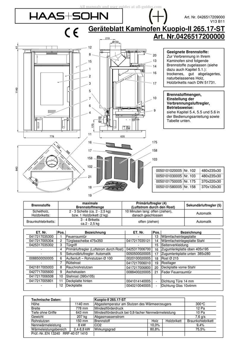
Haas+Sohn
Haas+Sohn Kuopio II Assembly instructions

Concept2
Concept2 OPK5860bc manual
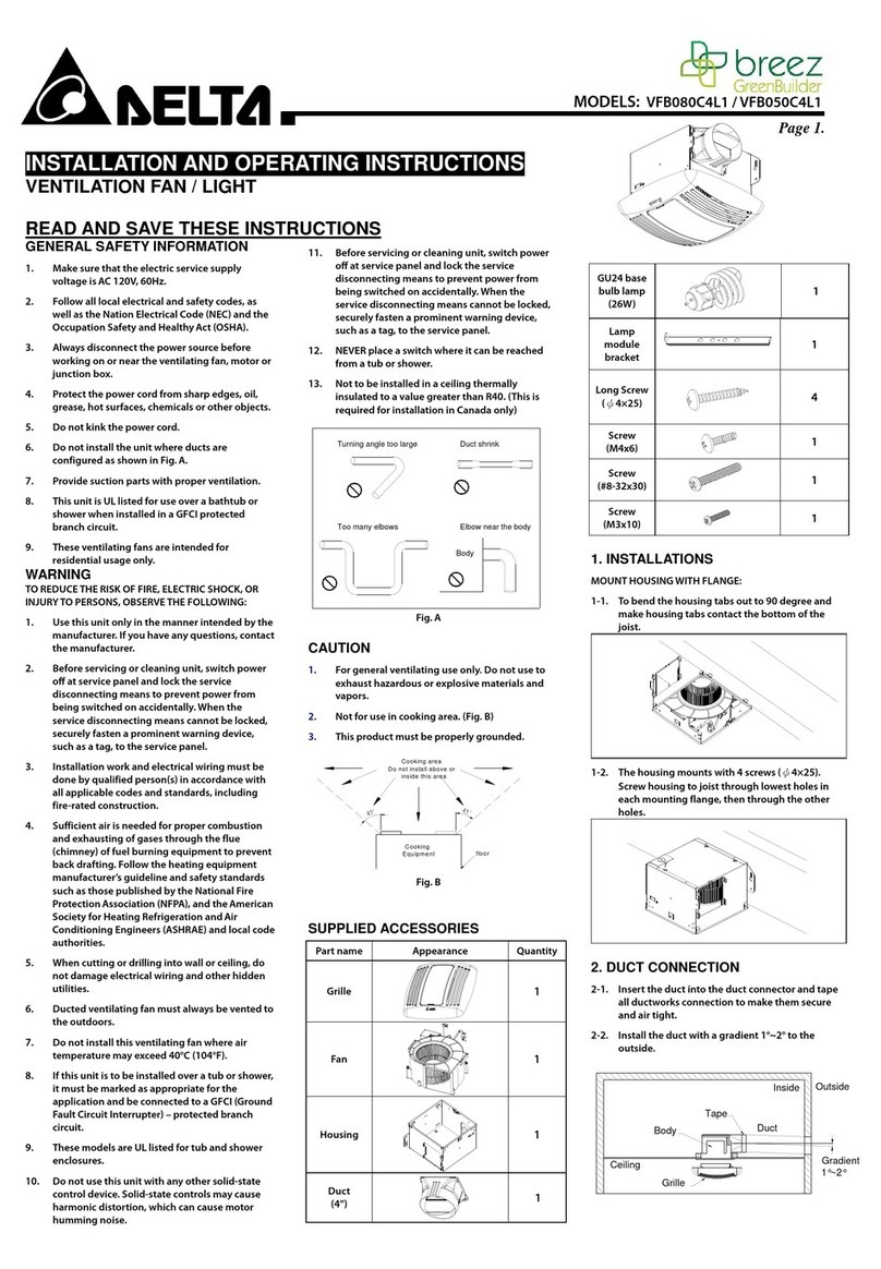
Delta
Delta VFB080C4L1 Installation and operating instructions
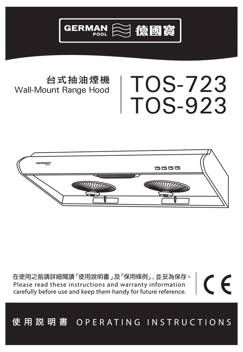
German pool
German pool tos-723 operating instructions

Blue Star
Blue Star PRO LINE PL30240 Installation use and care manual

Turboair
Turboair KR801 Instruction on mounting and use

Air King
Air King ESDQ Series operating manual
System air
System air Villavent 210 installation, user and maintenance instructions
Range Master
Range Master RMG2H60SS instruction manual

Air King
Air King APDQ Series operating manual
Wesco
Wesco WH Scala 110 Use and maintenance instructions
System air
System air Villavent 251-10/B User instructions

