Hauptsäge
Abmess. Quertisch mm 1420x650
Abmess. Schiebeschlitten mm 3200/3800
Abmessungen Tischverbreit. mm 1100x450
Abmessungen Sägetisch mm 885x700
Abmessungen Tischverläng. mm 650x700
Bohrung mm 30
Durchmesser Hauptsägeblatt max. mm 400
Durchmesser Hauptsägeblatt min. mm 300
Geschwindigkeit Hauptsägeblatt
U/min 3000 / 4000 / 5000
Länge Queranschlag mm 2100
(teleskopisch bis 3000 mm)
Vorritzer
Absaugstutzen mm 120 + 80
Bohrung mm 20
Durchmesser Vorritzsägeblatt mm 120
Geschwindigkeit Vorritzsägeblatt
U/min 8200
Schnitthöhe bei Durchmesser Vorritzblatt
120 mm mm 3,5
Schrägstellung Vorritzsägeblatt ° 90 - 45
Leistung Vorritzmotor kW 0,94
Leistung Hauptsägemotor ps 7, 5
Schrägverstellung ° 90 - 45
Schnittbreite am Parallelanschlag mm 1525
Schnitthöhe maximal (400 mm Blatt)
bei 45° mm 100
bei 90° mm 125
Schnittlänge mm 3200
Konfig.
Abmessungen Verpackung (LxWxH) mm
2270 x 1330 x 1020 + 3250 x 450 x 200
Betriebsspannung Drehstrom V 230 - 400
Gewicht kg 1050
Servoantrieb KEB 0.55 nm mit Resolver. Endlosschleife Sys-
tem für höchste Genauigkeit.
Standardbreite von 1525 Millimeter.
Schweres Alu-Extrusionsprofil.
Kugelumlaufspindel, Spielfrei.
Spielfreies Führungssystem.
Exakter Servo-Regler, sehr höhe Wiederholgenauigkeit.
Ausgestattet mit EMC Filter.
Standard mit Touch Screen.
Technische Daten
Technical Specifications
GR TE MARKT 20 - P STBUS 22
NL-4524 CD SLUIS - NEDERLAND
TEL: +31 (0)117-462880
FAX: +31 (0)117 462888
***
WWW.R BLANDMACHINES.C M
INF @R BLAND.C M
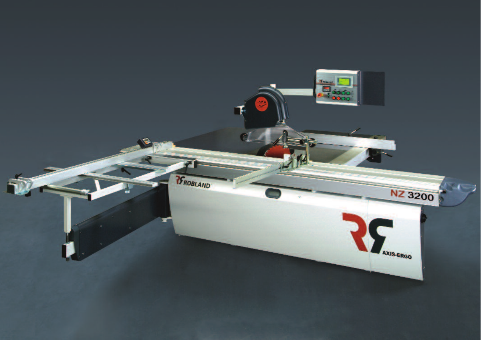
AXIS - ERGO
AXIS - ERGO
Configuration
Dimensions crate (LxWxH) mm 2270 x
1330 x 1020 + 3250 x 450 x 200
Voltage three phase V 230 - 400
Weight kg 1050
Main Saw
Dimensions cross-cut table mm 1420 x 650
Dimensions sliding table mm 3200/3800
Dimensions right hand table extension mm
1100 x 450
Dimensions sawtable mm 885 x 700
Dimensions saw table extension mm 650 x
700
Scoring saw
Dust suction ports mm 120 + 80
Bore mm 20
Diameter scoring saw blade mm 120
R.P.M. scoring saw R.p.m. 8200
Cutting depth with 120 mm diameter blade
mm 3,5
Scoring saw blade tilt ° 90 - 45
Scoring saw motor power kW 0,94
Auto Star-Delta starter standard.
Motorised rise, fall and tilt of the sawblades
as a standard.
Overhead control switch panel standard.
Bore mm 30
Diameter saw blade maximum mm 400
Diameter saw blade minimum mm 300
R.P.M. main saw blade R.p.m.
3000/4000/5000
Length cross-cut fence mm 2100 (tele-
scopes to 3000 mm)
Motor power main saw hp 7, 5
Sawblade tilting ° 90 - 45
Parallel rip capacity mm 1525
Cutting depth maximum
(400 mm saw blade) at 45° mm 100
Cutting depth maximum
(400 mm saw blade) at 90° mm 125
Saw stroke mm 3200
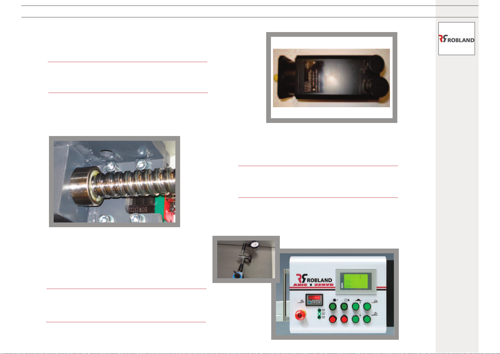
Servo motor KEB 0.55 nm with resolver. Closed loop system
for high and constant accuracy.
Standard width of 1525 mm.
Based on a stable machined aluminium extrusion.
Ball screw, free of backlash.
Guide free of backlash.
Precise servo-regulator to guarantee a very high
repetition accuracy.
Equipped with EMC filter.
Touch screen, easy to use.