10 10-V1011 Z3200 Z3200 10-V1011 11
–English–Deutsch
–English –Deutsch
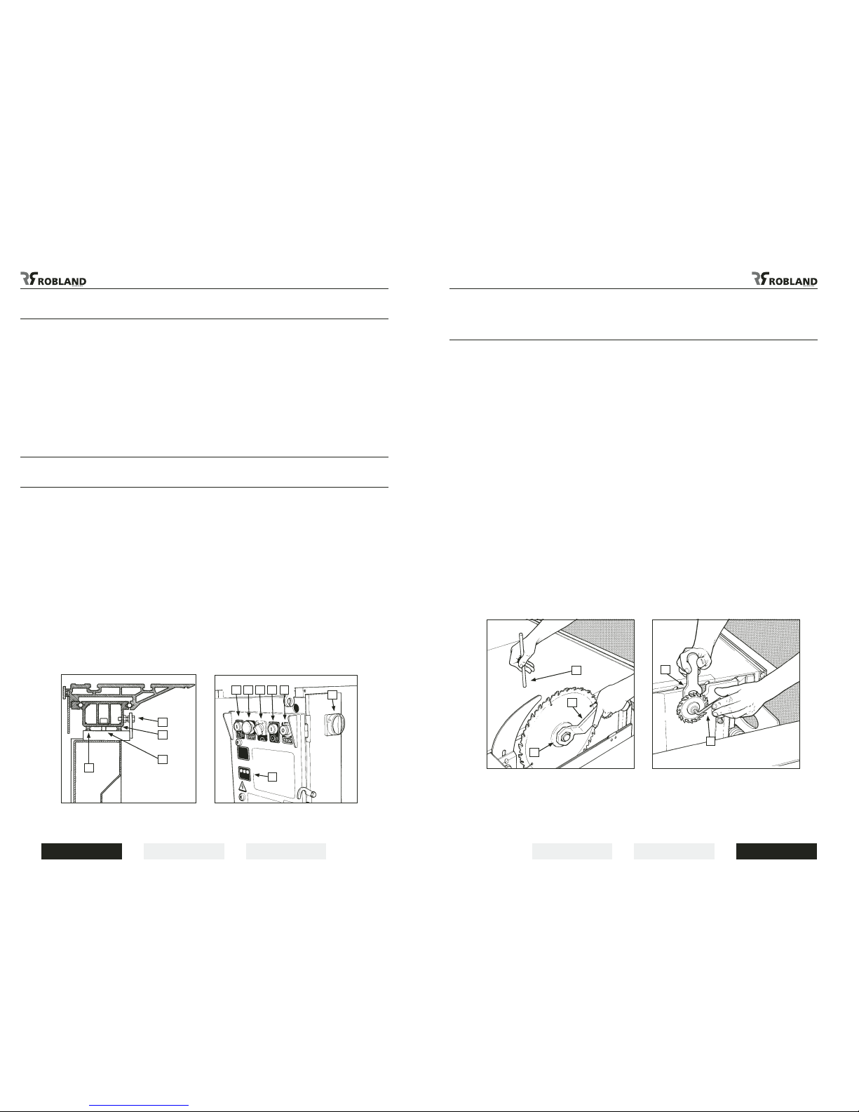
Changing main sawblade
and scorer sawblade (Fig.7-8)
Warning : Before changing sawblades always turn off the main switch.
Handle sawblades with care, to avoid serious cuts and injuries.
Push the sliding table to the rear and open the saw cover. Raise the main sawblade to its
highest position and put the key(3) into the saw arbor nut.
Put the locking pin (2) in the opening of the sawtable and turn the arbor with the key (3) until the
locking pin (2) engages in the hole in the saw arbor pulley.
Now unlock the nut. Before tting the new sawblade ensure the blade and anges are clean. This
prevents wobbling of the sawblade.
Never forget, after the saw arbor nut has been tightened, to remove the locking pin from the pulley
before starting up the motor.
atteNtioN :
Only sawblade diameters from 250 to 400 mm are allowed on the machine.
The use of HSS sawblades is strictly forbidden on all panelsaws; only use carbide-tipped
sawblades.
The scorer sawblade is changed as follows : turn the scorer blade to the left and put the key (1) onto
the atened arbor. Loosen the bolt with the Allen key (2) and put the scorer blade on. After changing
the blade tighten the bolt.
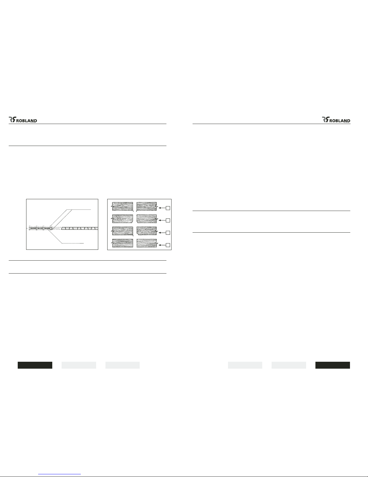
WarNiNg :
All main sawblades which are used on the panel saw must have two additional holes in the sawblade
body, to prevent the sawblade from loosening when the rotation of the saw arbor is stopped by the
brake on the motor.
The two little bolts in the xed saw arbor ange prevent the saw from coming off and may
under no circumstance be removed.
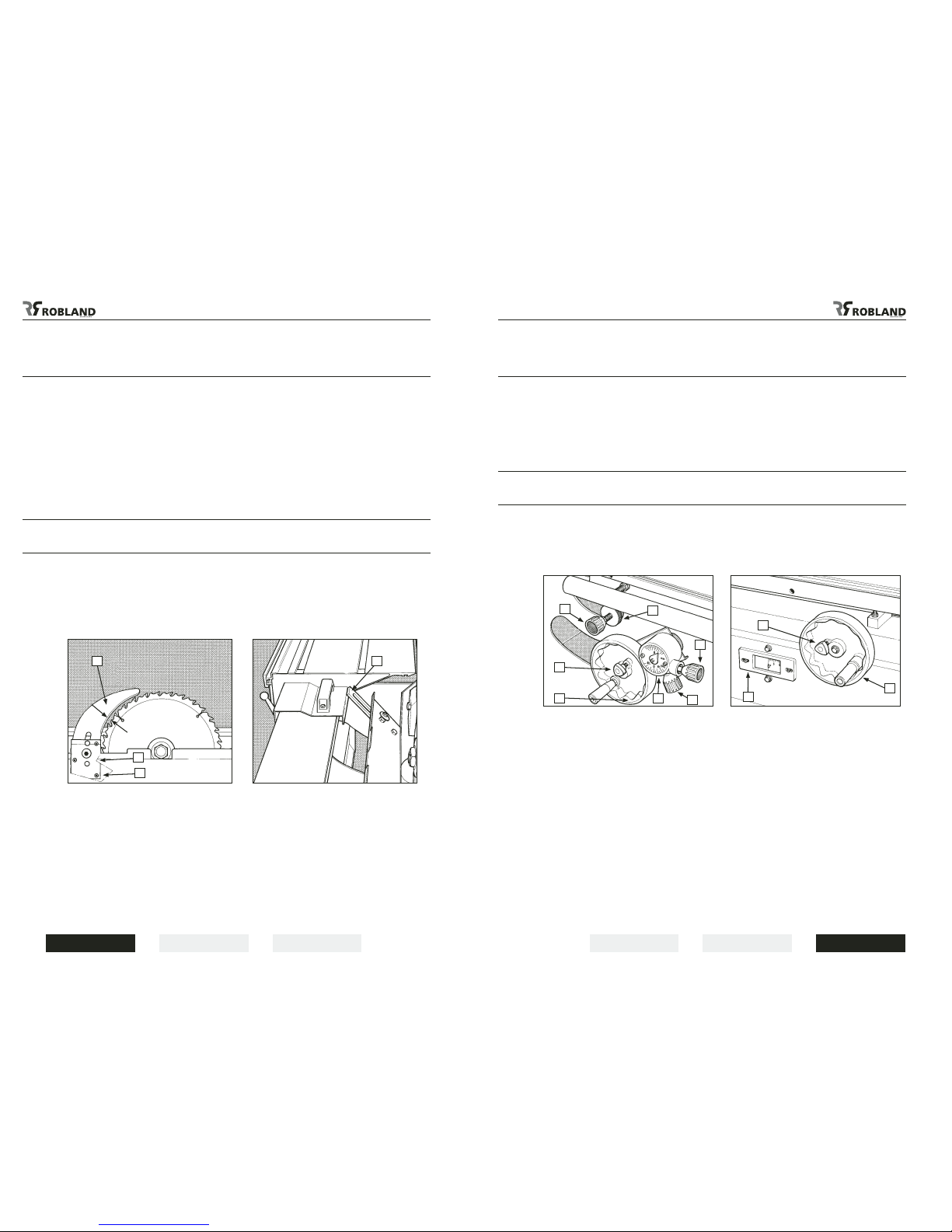
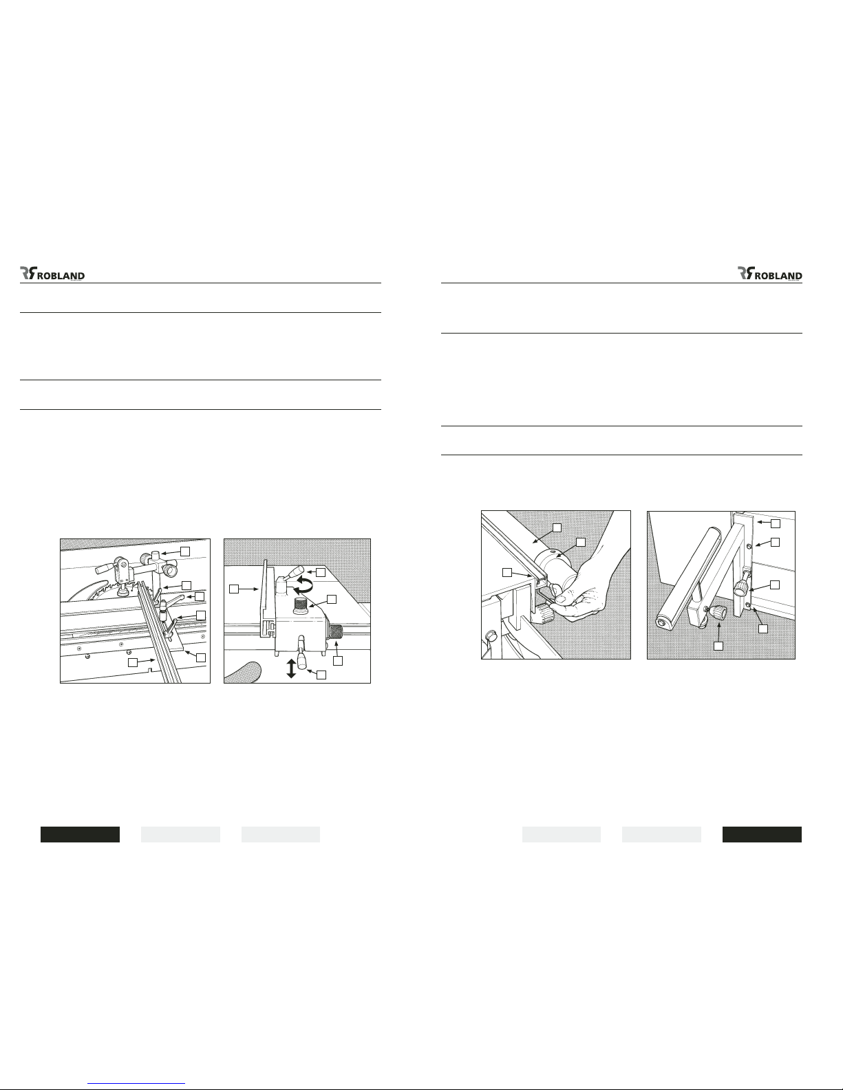
Mounting of the sliding table (Fig.5)
The position of the sliding table relative to the machine is factory set and needs no further
adjustments.
Simply put the table onto the frame with the two lateral adjustment bolts (1) in the two lugs placed at
the side of the frame.
These lateral adjustment bolts (1) are also factory set and normally need no adjustment.
Now place the 4 big Allen bolts (3) into the lower section of the sliding table. Ensure the table from
ipping over when sliding away the upper section of the sliding table.
These 4 bolts need to be well tightened.
The 8 small adjustment bolts (2) are height setting bolts set at factory. To ensure a clean and neat cut
the sliding table has to be set 100 % parallel to the sawblade.
To correct the parallelism between sliding table and sawblade, unlock the 4 big Allen bolts (3) and
adjust with one of the two parallel adjustment bolts (1).
After adjustment tighten the 4 big Allen bolts.
Starting up the machine (Fig.6)
Turn the main switch (1) to “1” and ensure that the star-delta switch (3) is put in position “star”.
To start the main saw motor push the start button (4). After about 8 seconds put the star-delta switch
(3) in position “delta”.
This time delay is needed to let the motor gain its full speed before switching over to “delta”.
When you forget to switch over from “star” to “delta”, the motor will reach its full speed but will have no
power, and will be damaged. The scorer motor is started by pushing the start button (6); this is only
possible with the main saw motor running.
By pushing the stop button (7) the scorer motor is stopped, when the emergency stop button (5) is
pushed both motors are stopped.
The main saw motor is equipped with an automatic brake which slows down the motor within 10
seconds as soon as the machine is shut off.
WarNiNg :
When the machine access door is open, it is impossible to start up the machine.
The RPM indicator lights at the front of the main switch panel show the speed of the saw spindle as
soon as the machine is switched on with the main switch (1).
All fuses can be found inside the electrical switch panel and each time this panel is opened the
machine has to be disconnected from its power supply.
Fig.5
Fig.7
1
21
2
3
1
Fig.6
Fig.8
4 5 3 6 7 1
2
2
2
3