8DR LED SERIES
INSTALLATION INSTRUCTIONS
H.E. Williams, Inc. Carthage, Missouri www.hew.com 417-358-4065
Information contained herein is subject to change without notice.
PN #49091089
Page 1 of 4
REV.09/14/18JJ
WARNING:
■This product must be installed in accordance with the applicable
installation code by a person familiar with the construction and
operation of the product and the hazards involved.
■Make sure all electrical power is turned off while installing the fixture.
■This luminaire must be adequately grounded for protection against
shock hazards and to assure proper operation.
■Disconnect power before servicing.
■LEDs are ESD (Electro Static Discharge) sensitive devices that can be
easily damaged if the proper ESD mitigating steps are not taken.
■LEDs are very sensitive to mechanical damage. Caution must be taken
to avoid damage to the LEDs.
■ESD or mechanical damage voids all warranties.
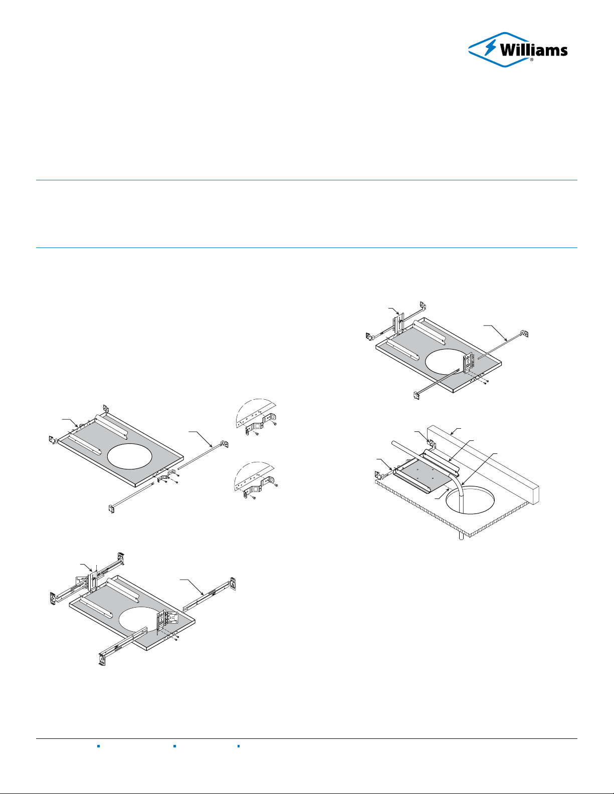
MOUNTING PAN INSTALLATION
Step 1: NEW CONSTRUCTION: Pre-attach the specified mounting
hardware to the fixture pan. See FIGURES 1.1 - 1.3.
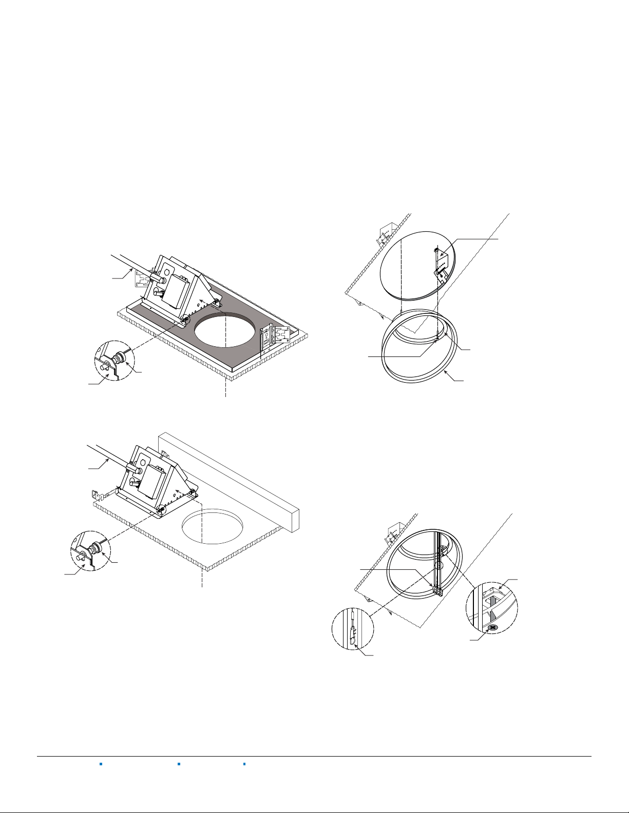
REMODEL: With the expandable bar hangers removed, maneuver
the receiver bracket assembly up through the ceiling cutout.
Once in the ceiling, reinstall the bar hangers, then position the
receiver bracket assembly 2” from the ceiling opening. Expand
the universal bar hangers until they stop against the ceiling joists
(both sides), then use a hammer to tap the nailer tabs into the
joists. See FIGURE 1.4.
FIG. 1.1 2-Position fixed pan bracket
F1: Universal bar hanger, shown | F2: T-bar clip hanger
Low position for
wood joist ceiling
High position for
1-11/16” T-bar grid
Universal
bar hanger
ed pan
et
FIG. 1.2 Adjustable butterfly pan bracket
BA1: Butterfly bracket only | BA2: Heavy-duty universal bar hanger, shown
Heavy-duty
universal
bar hanger
et
FIG. 1.3 Adjustable caterpillar pan bracket
CA1: Universal bar hanger, shown | CA2: T-bar clip hanger
bracket
Universal
bar hanger
FIG. 1.4
Nailer tab
Expandable
Receiver bracket assembl
Flex conduit
2”
MOUNTING PAN INSTALLATION CONTINUED ON NEXT PAGE
TABLE OF CONTENTS
MOUNTING PAN INSTALLATION.................................................................. 1
ELECTRICAL CONNECTIONS .......................................................................2
DRIVER BOX INSTALLATION ........................................................................ 3
SCA TRIM INSTALLATION ............................................................................. 3
DOWNLIGHT INSERT INSTALLATION........................................................ 4