manuals.online logo
Brands
  1. Home
  2. •
  3. Brands
  4. •
  5. Linergy
  6. •
  7. Lighting Equipment
  8. •
  9. Linergy PRODIGY PR08F10EBRT User manual

Linergy PRODIGY PR08F10EBRT User manual

APPARECCHIO DI EMERGENZA
EMERGENCY LUMINAIRE
ENERGY TEST
NON PERMANENTE
IP 42
ISTRUZIONI PER L'INSTALLAZIONE E L'USO
INSTALLATION AND USE INSTRUCTIONS
I
UK EN 60598-1 EN 60598-2-22
2002/95/CE RoHS Compliant
MADE IN ITALY
230 Vac - 50 Hz
IP 65
3
21
5 6
1.RUOTARE
IL GIRAVITE NELLA
FESSURA INDICATA
2.SOLLEVARE
IL VETRO
3.SOLLEVARE
IL RIFLETTORE CON
IL CACCIAVITE
3.SOLLEVARE
IL RIFLETTORE
CON IL CACCIAVITE
4.SOLLEVARE LA
BASE
4.TAGLIARE LE
PREDISPOSIZIONI
SULLA CORNICE (PASSAGGIO CAVI)
FISSARE LA BASE
AL MURO
FISSARE IL RIFLETTORE CON
IL LED VERDE VERSO SINISTRA
1.ROTATE
THE SCREWDRIVER
AS SHOWN IN THE PICTURE
2.LIFT
THE GLASS
3.LIFT THE REFLECTOR
WITH THE SCREWDRIVER
AS SHOWN IN THE PICTURE
4.LIFT THE BOX
4.CUT
PREPARATIONS
ON THE FRAME (CABLES ENTRY)
FIX THE REFLECTOR WITH
THE GREEN LIGHT TO THE LEFT
FIX THE BASE
TO THE WALL
N.B. SUI MODELLI IP65, MONTARE IL RACCORDO PERFETTAMENTE
AL CENTRO DELLA PREROTTURA LATERALE
ROMPENDO ANCHE LA CORNICE DELLA BASE**(DETTAGLIO FIG.4)
N.B. ON THE IP65 MODELS, PUT THE IP65 CONNECTOR ON THE
BOX AND THEN DRILL THROUGH THE ALL LAMP WITHOUT CARE
ABOUT THE FRAME*(DETAIL PIC.4).
4
DIAMETRO DEL FORO
Ø16.5
4.FORARE
LE PREDISPOSIZIONI
CON LA PUNTA CONICA 4.DRILL
THE PREPARATIONS
WITH CONICAL TIP
HOLE DIAMETER
Ø16.5
DETTAGLIO CORRETTO
POSIZIONAMENTO
DELLA PUNTA CONICA
DETTAGLIO ROTTURA
CORNICE DELLA BASE
CORRECT DETAIL
OF THE DRILL POSITION
TO USE
CORNICE*
FRAME*
BOX**
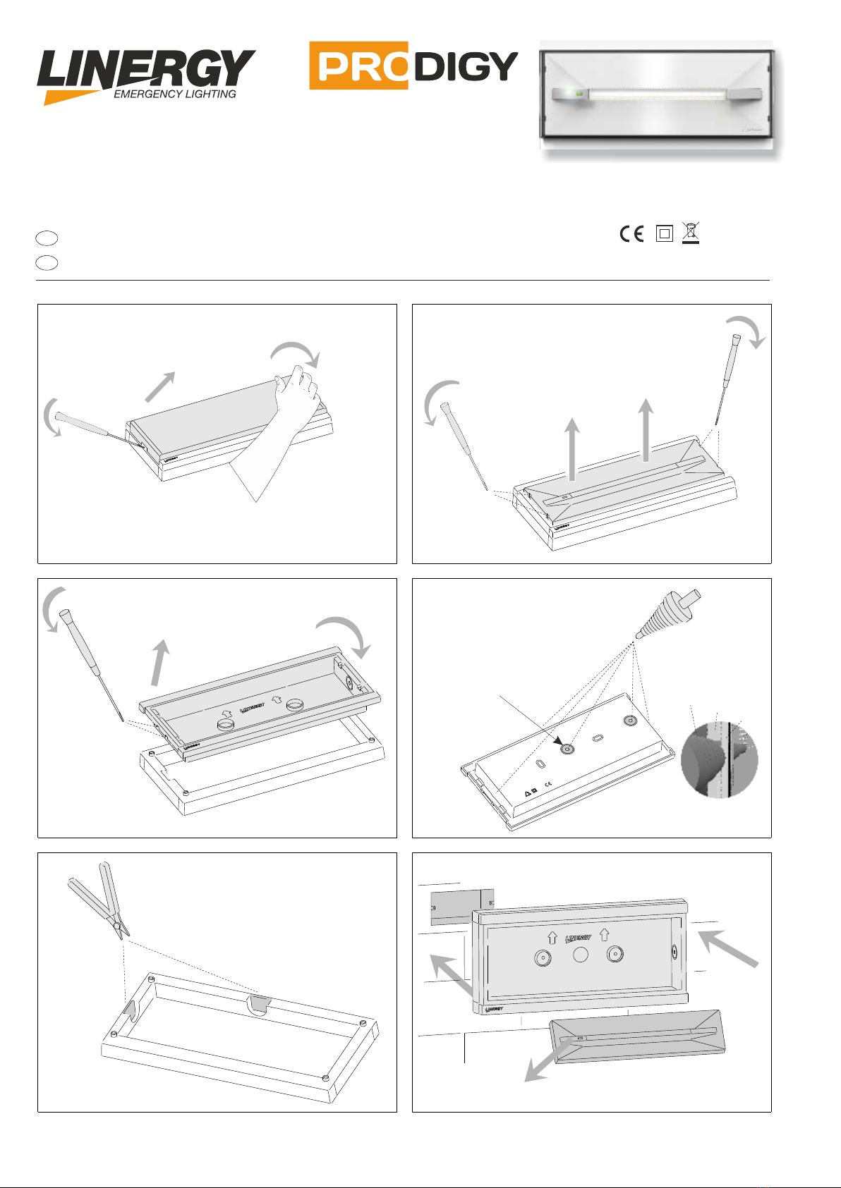
COLLEGAMENTI ELETTRICI - WIRING DIAGRAMS
A
Attenzione: In caso di utilizzo dell’art. COMMANDER non collegare il ponte a filo su A-B, e una volta effettuato il collegamento come la linea tratteggiata
IN PRESENZA DI RETE, tenere premuto per 10 s il tasto ON, affinché la lampada si configuri in “MODO DI RIPOSO”.
NOTA: Da questa situazione è possibile ritornare alla configurazione di fabbrica spingendo il tasto OFF per 10 s.
Attention: When using the COMMANDER do not connect the jumper wire on A-B and, once the connection is made as in figure 6-7 (broken line),
WITH THE MAINS SUPPLY ON hold the ON button for 10 s so that the lamp gets configured in “REST MODE.
NOTE: from this situation it is possible to return to the factory default configuration by pushing the OFF button for 10 s.
CONFIGURAZIONE - CONFIGURATION COMMANDER
MAINS SUPPLY ON, NO WARNING
TEST DISABLED, INHIBIT LUMINAIRE
BATTERY FAULT
WARNING LUMINAIRE
SEGNALETICA LED / LED SIGNALLING
VERDE ACCESO FISSO / GREEN ON PRESENZA RETE, NESSUNA ANOMALIA
TEST IN CORSO / TEST IN PROGRESS
TEST DISABILITATI, LAMPADA INIBITA
GUASTO BATTERIA
ANOMALIA LAMPADA
VERDE LAMPEGGIANTE / GREEN FLASHING
ROSSO LAMPEGGIANTE LENTO / RED SLOW FLASHING
ROSSO LAMPEGGIANTE VELOCE / RED FAST FLASHING
ROSSO ACCESO FISSO / RED ON
FUNZIONI DI TEST
- La lampada esegue due tipi di test temporizzati: il test funzionale e il test
di autonomia. I test funzionale e di autonomia possono essere effettuati
anche manualmente con il Commander quando la batteria è in ricarica di
mantenimento.
Durante il tempo di attesa il led verde lampeggia per segnalare che la
lampada sta aspettando di potere compiere i test.
Test funzionale: viene effettuato ogni 15 giorni e consiste nella
accensione della lampada fluorescente per una durata di 20 secondi. Per
attivare il test funzionale manuale premere una volta il Commander ON
(effettuare una pressione breve della durata non superiore a 2 secondi)
Test di autonomia: viene effettuato ogni 90 giorni e consiste nella
completa scarica della batteria. P e il test di autonomia er far partir
premere una volta il Commander ON (effettuare una pressione lunga
della durata non inferiore a 10 secondi).
Disabilitazione dei test: tutti i test temporizzati possono essere inibiti
tramite la pressione di un tasto del Commander OFF, ad una seconda
pressione del tasto ON i test temporizzati verranno riabilitati.
TEST FUNCTIONS, ONLY FOR SELF TEST MODELS - ABRT:
-The lamp makes two types of deliberate time tests: the functional test and the duration
test. The functional test and the duration test can be made also in the manual way with
the use of the Commander in the normal charge mode.
In the time of waiting the green led flashes to indicate that the lamp is waiting for the
test.
The functional test: is done every 15 days and consists in the lighting of the
fluorescent lamp for a duration of 10 seconds. To start the manual functional test push
one time the Commander ON (make a short push no more than 10 seconds)
The duration test: is done every 90 days and consists in the complete discharge of the
battery. To start the duration test push one time the Commander ON (make a long push
no less than 5 seconds).
Disabilitation of the tests: all deliberate time tests can be disabled with a pushing of
the button of Commander OFF, with a second pushing of the Commander ON
deliberate time tests will be enabled.
Fig. 1
COLLEGAMENTI ELETTRICI REST MODE CON COMMANDER
WIRING DIAGRAMS REST MODE WITH COMMANDER
Fig. 2
NOTE: NON COLLEGARE PRODIGY ENERGY TEST E REST MODE NELLA STESSA LINEA COMMENDER
NOTE: DO NOT CONNECT PRODIGY ENERGY TEST AND REST MODE ON THE SAME COMMANDER LINE
APPLICAZIONE DEL PITTOGRAMMA DI SEGNALAZIONE
APPLICATION OF THE SIGNALING PICTOGRAM
1
1.RUOTARE
IL GIRAVITE NELLA
FESSURA INDICATA
2.SOLLEVARE
IL VETRO
2
4.ESTRARRE
LA LENTE
3.SOLLEVARE LA
LENTE CON UN
GIRAVITE
3
5.APPLICARE IL
PITTOGRAMMA ADESIVO
SUL VETRO
4
6.RIPOSIZIONARE IL
VETRO SUL CORPO
LAMPADA
3.REMOVE
THE LENS
1.ROTATE
THE SCREWDRIVER
AS SHOWN IN THE PICTURE 3.LIFT THE LENS
WITH THE SCREWDRIVER
AS SHOWN IN THE PICTURE
5.PUT
THE SIGNAL
LABEL ON THE GLASS
6.REPLACE THE
GLASS ON THE
BODY LAMP
CENTRALIZZATE SPY SYSTEM / CENTRALIZED SPY SYSTEM
230V~ 50Hz SE
A B
L N
Fig. 3
- NON PERMANENTE/NOT MAINTAINED
COLLEGAMENTI ELETTRICI / WIRING DIAGRAMS
Respect the polarity of the Bus.
B
B
A
A
Rispettare la polarità del Bus. The Bus:
The bus used for the Spy System must have a
bipolar, twisted and shielded cable (min. 2x0,5
mm²). The connection is a Point to Point type,
i.e. input and output of the fixtures must be,
as shown in fig. no. 2. The connection must be
done respecting the polarity of "A" and "B"
both on the lamps and on the plant.
Il Bus:
Il Bus che deve essere utilizzato per lo Spy
System deve avere un cavo bi-polare (minimo
2
2x0,50mm ) twistato e schermato. La tipologia di
connessione deve essere Punto Punto, ossia si
deve entrare ed uscire da ogni plafoniera come è
visibile negli schemi a lato. Il collegamento deve
essere fatto rispettando le polarità di “A” e “B” sia
sulle lampade che sulla centrale.
LINERGY SRL - Via A. De Gasperi 9 - Acquaviva Picena (AP) - ITALY - tel.0735.5974 - fax 0735.597474 - www.linergy.it - info@linergy.it - ISTPRODIGY-ET-SE Ver.1.1
Il cassonetto barrato sull’apparecchio specifica che il prodotto deve essere
consegnato ai centri di raccolta autorizzati per un corretto smaltimento. Rivolgersi
all’ufficio competente del proprio ente locale per informazioni sulla raccolta e sui
termini di legge.
The crossed out waste bin symbol indicates that the product should be taken to
an authorized waste collection centre which can dispose of it properly. For
information on waste collection centres and on current waste disposal legislation,
please contact your local waste disposal authority.
ATTENZIONE
La sorgente luminosa a LED non è sostituibile.
WARNING
LED source is not replaceable.
TABELLA DEI MODELLI
MODELS TABLE
Sostituire la batteria ogni quattro anni o quando l'autonomia
non è più quella nominale. Sulla batteria c’è a disposizione uno
spazio da riempire a cura dell'installatore con la data di entrata
in funzione.
Attenzione: Le batterie al LiFePo4 sono inizialmente
scariche, la prima ricarica deve durare almeno 48h.
ALIMENTAZIONE/ POWER SUPPLY
POTENZA ASSORBITA IN RICARICA/ POWER ABSORPTION
GRADO DI PROTEZIONE/ PROTECTION DEGREE
CLASSE DI ISOLAMENTO/ INSULATING CLASS
CARATTERISTICHE TECNICHE/TECHNICAL CHARACTERISTICS
230Vac - 50Hz
2,3W SE
IP42-IP65
II
TEMPERATURA DI LAVORO/WORK TEMPERATURE T=0° ÷ 40°C
GENERAL CHARACTERISTICS:
- Indicator green Led for the presence of the power supply.
- Operation with rechargeable LiFePo4 batteries.
- Constant current electronic device for the charge of the battery.
- Electrical protection device for the excessive discharge of battery.
- Possibility to be put in the stand-by mode by remote control Commander
(optional)
- Possibility to put a green signal label .
- Plastic body in accordance with the rules in force.
CARATTERISTICHE GENERALI:
- Led spia verde per presenza rete.
- Funzionamento con batterie ricaricabili al LiFePo4.
- Dispositivo di ricarica delle batterie a corrente costante.
- Dispositivo di protezione contro la scarica eccessiva della batteria.
- Possibilità di messa in stato di riposo tramite il comando remoto Commander
(opzionale).
- Possibilità di applicare dei pittogrammi di segnalazione.
- Corpo in materiale plastico conforme alle normative vigenti.
CONDIZIONI DI GARANZIA / WARRANTY CONDITION
La garanzia sugli apparecchi di emergenza è di 2 anni dalla data di
vendita. La garanzia decade se il prodotto è stato manomesso o
riparato da personale non autorizzato LINERGY.
The warranty on the emergency luminaire is 2 years from the sales
date. The warranty voids if the product has been mishandled or
repaired by personnel not authorized by LINERGY.
CODICE MODELLO
CODE MODEL
IP42
CODICE MODELLO
CODE MODEL
IP65
N.
LED
LUCE
PARAGONABILE
LIGHT
COMPARABLE
AUTONOMIA
DURATION
TIPO
TYPE
FLUSSO MEDIO
(lm) SE
AVERAGE FLUX
(N/M)
BATTERIA
BATTERY
RICARICA
RECHARGE
PR08F10EBRT PS08F10EBRT 10 8W 1h SE 70 LIFEPO4 3.2V 0.55Ah 12h
PR08F30EBRT PS08F30EBRT 10 8W 3h SE 70 LIFEPO4 3.2V 1.5Ah 12h
PR11F10EBRT PS11F10EBRT 10 11W 1h SE 130 LIFEPO4 3.2V 1.5Ah 12h
PR11F30EBRT PS11F30EBRT 10 11W 3h SE 130 LIFEPO4 3.2V 3Ah 12h
PR24F10EBRT PS24F10EBRT 20 24W 1h SE 210 LIFEPO4 3.2V 1.5Ah 12h
PR24F30EBRT PS24F30EBRT 20 24W 3h SE 210 LIFEPO4 3.2V 3Ah 12h
CODICE MODELLO
CODE MODEL
IP42
CODICE MODELLO
CODE MODEL
IP65
PR08F10EBRC PS08F10EBRC
PR08F30EBRC PS08F30EBRC
PR11F10EBRC PS11F10EBRC
PR11F30EBRC PS11F30EBRC
PR24F10EBRC PS24F10EBRC
PR24F30EBRC PS24F30EBRC
ENERGY TEST ENERGY TEST SPY SYSTEM SPY SYSTEM

This manual suits for next models

5

Other Linergy Lighting Equipment manuals

Linergy EI58SA/E User manual

Linergy

Linergy EI58SA/E User manual

Linergy PRODIGY PR08F10EBR Operating and maintenance manual

Linergy

Linergy PRODIGY PR08F10EBR Operating and maintenance manual

Linergy PRODIGY Quick start guide

Linergy

Linergy PRODIGY Quick start guide

Linergy VA03N20EBRD User manual

Linergy

Linergy VA03N20EBRD User manual

Linergy STEP Operating and maintenance manual

Linergy

Linergy STEP Operating and maintenance manual

Linergy ASTRA Operating and maintenance manual

Linergy

Linergy ASTRA Operating and maintenance manual

Linergy VIALED EVO-HIGH User manual

Linergy

Linergy VIALED EVO-HIGH User manual

Linergy PS08F10EBRT Quick start guide

Linergy

Linergy PS08F10EBRT Quick start guide

Linergy VIALED IP65 User manual

Linergy

Linergy VIALED IP65 User manual

Linergy SU30N10AGR Product manual

Linergy

Linergy SU30N10AGR Product manual

Linergy LEDY Instruction Manual

Linergy

Linergy LEDY Instruction Manual

Linergy LEDY LD100L10EBR Instruction Manual

Linergy

Linergy LEDY LD100L10EBR Instruction Manual

Linergy LYRA EVO Product manual

Linergy

Linergy LYRA EVO Product manual

Linergy SELFIE User manual

Linergy

Linergy SELFIE User manual

Linergy VIALED NET User manual

Linergy

Linergy VIALED NET User manual

Popular Lighting Equipment manuals by other brands

Sunnydaze Decor WNC-321 quick start guide

Sunnydaze Decor

Sunnydaze Decor WNC-321 quick start guide

Boost BLGL-Al-A60-20-A66-Al installation guide

Boost

Boost BLGL-Al-A60-20-A66-Al installation guide

LED's light Pro 2400380 Operation & installation manual

LED's light Pro

LED's light Pro 2400380 Operation & installation manual

TOPIC-LIGHT Celeb 2 manual

TOPIC-LIGHT

TOPIC-LIGHT Celeb 2 manual

SGM P Series user manual

SGM

SGM P Series user manual

MELINERA HG01751A Operation and safety notes

MELINERA

MELINERA HG01751A Operation and safety notes

ACME Colortec 250 user guide

ACME

ACME Colortec 250 user guide

Beamz Pro NUKE2 user manual

Beamz Pro

Beamz Pro NUKE2 user manual

Experia Superactive LED Fibre Optic Bundle instruction manual

Experia

Experia Superactive LED Fibre Optic Bundle instruction manual

XKGlow XK052002 manual

XKGlow

XKGlow XK052002 manual

ADJ X-SCAN LED PLUS User instructions

ADJ

ADJ X-SCAN LED PLUS User instructions

VISIO BW-54-3RGBW IV user manual

VISIO

VISIO BW-54-3RGBW IV user manual

Avlite AV-70 Installation & service manual

Avlite

Avlite AV-70 Installation & service manual

LUX LUMEN StarLine manual

LUX LUMEN

LUX LUMEN StarLine manual

Starling Technologies Pocket Spin Drift instruction manual

Starling Technologies

Starling Technologies Pocket Spin Drift instruction manual

EuroLite LED T-36 user manual

EuroLite

EuroLite LED T-36 user manual

American DJ UV Canon User instructions

American DJ

American DJ UV Canon User instructions

ProLights EclFresnel 2KTW user manual

ProLights

ProLights EclFresnel 2KTW user manual

manuals.online logo
manuals.online logoBrands
  • About & Mission
  • Contact us
  • Privacy Policy
  • Terms and Conditions

Copyright 2025 Manuals.Online. All Rights Reserved.