Robur G 30 Service manual

Gas unit heatersproduct line
GSeries
Condensing and modulating Gas Fired Unit Heaters
to heat medium large areas
Natural gas/LPG fired
Installation, use and
maintenance manual

EDITION: 09/2018
Code: D-LBR565
This manual has been written and printed by Robur S.p.A.; the reproduction even partial
of this manual is forbidden.
The original isarchived at Robur S.p.A.
Any use ofthis manual other than for personal consultation must be previously authorised
by Robur S.p.A.
The rights ofthose who have legitimately filed the registered trademarks contained within
this publication are not affected.
With the aim of continuously improving the quality of our products, Robur S.p.A. reserves
the right tomodify instructions, drawings and data contained in this manual without prior
notice.

Condensing Gas Fired Unit Heaters – G Series: Manual of installation, use and maintenance
Ed. 09/2018 I
FOREWORD
This manual is intended for those people who need to install and use the Robur G Series
condensing Gas Fired Unit Heaters.
In particular this manual is addressed to the hydraulic installation technician who shall
install the generator, the electrical installation technician who shall connect the generator
to the power supply and the final user who shall check its normal working. This manual is
also addressed to the Technical Assistance Centres for the main service operations.
Summary
This manual is based on five sections
Section 1 is intended for end user, plumber installer , electrical installer and technical
assistance service; it furnishes general instructions, technical data and general
information of the Gas Fired Unit Heaters G series.
Section 2 is intended for end user; it furnishes all information for the correct use of Gas
Fired Unit Heaters G series.
Section 3 is intended for the plumber installer; it furnishes the information for a correct
installation of Gas Fired Unit Heaters Gseries.
Section 4 is intended for electrical installer; it furnishes the information for correct
electrical connections of the Gas Fired Unit Heaters Gseries.
Section 5 is intended for technical assistance service; it furnishes the instructions to set
the gas flow and to change the type of gas. It reports also information about maintenance.
Meaning of Icons
The icons placed on the margin of the pages of this manual have the following meaning:
Danger signal
Warning
Note
Start of operating procedure
Reference to another part of the manual or to another
manual/book
Table 1 – Descriptive Icons.

Condensing Gas Fired Unit Heaters – G Series: Manual of installation, use and maintenance
Ed. 09/2018 1
TABLE OF CONTENTS
Section1: GENERAL INFORMATION AND TECHNICAL CHARACTERISTICS..............2
1.1 GENERAL WARNINGS.....................................................................................................................2
1.2 OPERATION OF THE UNIT ..............................................................................................................3
1.3 CONSTRUCTIVE CHARACTERISTICS............................................................................................5
1.4 TECHNICAL DATA ............................................................................................................................6
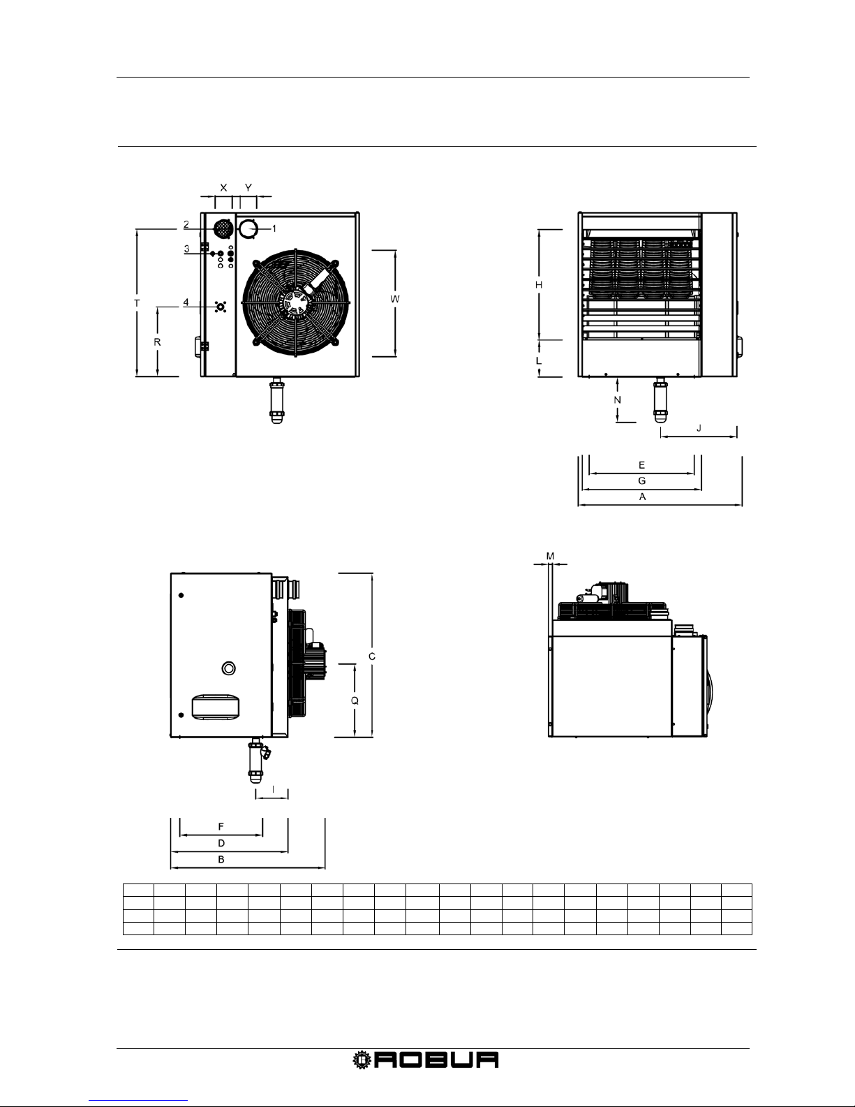
1.5 DIMENSIONS OF G SERIES GAS FIRED UNIT HEATER...............................................................7
section 2: END USER........................................................................................................9
2.1 FUNCTIONS OF CHRONOTHERMOSTAT......................................................................................9
2.2 SETTING THE TIME AND DAY ON THE CHRONOTHERMOSTAT............................................. 10
2.3 SETTING THE COMFORT, ECONOMY AND ANTI- FREEZING TEMPERATURES ON THE
CHRONOTHERMOSTAT ............................................................................................................... 10
2.4 PROGRAMMING OF THE DAILY SET POINT ON THE CHRONOTHERMOSTAT...................... 11
2.5 SELECTING A PRESET DAILY PROFILE ON THE CHRONOTHERMOSTAT ............................ 13
2.6 SELECTING A PRESET WEEKLY PROFILE ON THE CHRONOTHERMOSTAT........................ 13
2.7 TIMED FUNCTIONS OF THE CHRONOTHERMOSTAT............................................................... 15
2.8 KEYBOARD BLOCK....................................................................................................................... 17
2.9 INFORMATION SCREEN OF THE CHRONOTHERMOSTAT....................................................... 18
2.10 SELECTION MENU WINDOW ....................................................................................................... 19
2.11 MALFUNCTION WARNINGS ......................................................................................................... 20
2.12 TABLE OF ICON MEANINGS ON CHRONOTHERMOSTAT DISPLAY........................................ 22
2.13 HOW TO USE THE UNIT HEATER................................................................................................ 23
2.14 HOW TO USE THE UNIT WITH THE CHRONOTHERMOSTAT.................................................. 25
2.15 HOW TO USE THE UNIT WITHOUT A CHRONOTHERMOSTAT................................................ 30
2.16 SETTING FIELD.............................................................................................................................. 31
2.17 END OF SEASON........................................................................................................................... 32
section 3: PLUMBER INSTALLER..................................................................................33
3.1 GENERAL RULES FOR INSTALLATION OF THE APPLIANCE................................................... 33
3.2 INSTALLATION SEQUENCE ......................................................................................................... 33
3.3 SIZE AND INSTALLATION OF THE AIR INLET / EXHAUST FLUE.............................................. 35
3.4 CONDENSATE DRAINAGE ........................................................................................................... 44
section 4: ELECTRICAL INSTALLER.............................................................................46
4.1 HOW TO CONNECT THE HEATER TO THE ELECTRICAL SYSTEM......................................... 46
4.2 HOW TO CONNECT THE CHRONOTHERMOSTAT TO THE HEATER ...................................... 46
4.3 UNIT OPERATION WITH EXTERNAL CONSENT......................................................................... 47
4.4 REMOTE SIGNALLING OF THE ANOMALIES.............................................................................. 48
4.5 INSTALLATION WIRING DIAGRAM .............................................................................................. 49
4.6 WIRING DIAGRAM FOR MULTIPLE HEATER WITH ONE PROGRAMMER............................... 50
section 5: ASSISTANCE AND MAINTENANCE.............................................................52
5.1 START UP OF THE UNIT............................................................................................................... 52
5.2 HOW TO REGULATE THE GAS VALVE ....................................................................................... 52
5.3 CONVERSION TO ANOTHER TYPE OF GAS.............................................................................. 54
5.4 MAINTENANCE.............................................................................................................................. 55

Condensing Gas Fired Unit Heaters – G Series: Manual of installation, use and maintenance
2 Ed. 09/2018
SECTION1: GENERAL INFORMATION AND TECHNICAL
CHARACTERISTICS
In this section you can find the general warnings to follow for the installation and use of
the Condensing Gas Fired Unit Heaters G Series, a short description of the heater
operation, design characteristics and technical data.
1.1 GENERAL WARNINGS
This manual is an integral and essential part of the product and must be given to the final
user.
This appliance must be exclusively used for the purpose it was intended. Any other use is
to be considered improper and therefore dangerous.
The unit must not be used by persons (children included) with lack of physical or mental
disease or not experienced. Children must be supervised to be sure that they do not
play with the unit.
The Manufacturer will not be held responsible for damages resulting from installation
errors or failure to comply with the Manufacturer’s instructions.
The appliance must be installed in compliance with the rules and regulations in force.
Do not obstruct the fan intake opening or the air delivery grids.
In case of failure and/or malfunction of the appliance, isolate the unit (disconnect it
from the power supply and close the main gas cock), do not attempt any repair or
direct servicing.
The Manufacturer’s Authorised Service Centres using only original spare parts
must only carry out any repair to the products.
The non-observance of the above-mentioned provisions may compromise the safety of
the unit.
To ensure unit efficiency and correct operation, it is essential that qualified service
engineers carry out annual maintenance following the Manufacturer’s instructions.
By the term Qualified Service Engineers it is meant the personnel having specific
technical skills in the field of heating system components for civil use. In any case for
more information please contact the Technical Assistance Office of ROBUR S.p.A.
(tel. +39 035/888111).
Should the unit be sold or transferred to another owner, please ensure that the manual
remains with the unit for use by the new owner and/or installer.
Before turning the heater on, a qualified service engineer must check:
- that electric and gas supply ratings are the same as those given in the data plate;
-that the exhaust duct operates correctly;
- the correct functioning of the condensate drainage;
-that combustion air feed and exhaust occur correctly according to the existing
standards;

Condensing Gas Fired Unit Heaters – G Series: Manual of installation, use and maintenance
Ed. 09/2018 3
-the internal and external tightness of the fuel supply system;
-fuel flow control according to the heater power requirements;
-that the heater is supplied with the type of fuel for which it is pre-set.;
-that the gas supply pressure is within rating limits;
-that the gas supply system is suitable to the heater and all safety and check-over
devices prescribed by existing standards are duly installed;
Do not use gas pipes to ground the appliance, or any other electrical appliances.
Avoid unnecessary supply when unit is not in use and always clock the main gas
cock. If the appliance is turned off for a longer time period, close the main gas
supply cock and cut off the power supply.
IF YOU SMELL GAS
•Do not operate electric switches, telephones and any other object or device
which may cause sparks.
•Shut-off the gas supply.
•Open immediately doors and windows to create a cross-current of air to purify
the room.
•Call for a qualified service engineer.
1.2 OPERATION OF THE UNIT
The G Series gas fired unit heater is an independent heater appliance with airtight
combustion circuit and forced air draft.
It is designed for an indoor installation - inside the area to be heated.
It is adjustable for the use of Natural Gas (G20) and L.P.G. (G30/G31) (appliance
belonging to the II2H3B/P category according to the Standard EN 1020).
The combustion circuit is airtight with respect for the heated environment and conforms to
the ordinances of regulations EN 1020 and EN 1196 for C type appliances: the air inlet of
the combustion air and the flue exhaust are outdoors and are ensured through the
operation of combustion blower.
A room thermostat, integrated in a chronothermostat, controls the heater operation.
When the thermostat is turned on the flame control box, after the pre-purge period (about
40 seconds), ignites the burner.
The flame sensor controls the ignition of the burner. If the flame does not appear the
flame control unit locks out the heater.
The combustion products pass through the heat exchangers, the air flow given by the
axial fan provides warm air to the room.
The airflow direction is regulated by means of adjustable horizontal louvres.
The fan control thermostat allows the axial-flow fan to start automatically only when the
heat exchangers are hot (after about 60 sec. from the flame detection or when the
temperature of 60°C is reached on the exchanger thermostat) and to turn off when they
are cold. This prevents cool air from being blown into the room.

Condensing Gas Fired Unit Heaters – G Series: Manual of installation, use and maintenance
4 Ed. 09/2018
If heat exchangers overheat due to malfunction, the temperature limit thermostat cuts off
the supply to the gas valve by setting the blower and the fan to the maximum speed;
should the temperature increase further, the limit thermostat comes into operation causing
the switching off of the heater. The limit thermostat reset is manual.
After removing the cause of overheating, Qualified service engineers should carry
out resetting of the temperature.
Ahead of the burner the flue fan is installed which makes the air-gas mixture and forces
draft of the exhaust flues.
In case of obstructions in the exhaust or intake duct or in case of blower malfunction, the
flame control box intervenes immediately with the modulation of the heater. In case of
obstructions or malfunction beyond the allowed limits, the differential pressure switch
closes the gas valve and consequently stops the fuel flow to the burner.
For winter operation the heating unit can be used in either automatic or manual mode. For
further information see paragraph “WINTER OPERATING (HEATING)” at page 25.
In the summer time it is possible to activate only the axial fan to provide pleasant and
refreshing air movement in the room (for more information see Paragraph “SUMMER
OPERATION (VENTILATION ONLY)” at page 29).

Condensing Gas Fired Unit Heaters – G Series: Manual of installation, use and maintenance
Ed. 09/2018 5
1.3 CONSTRUCTIVE CHARACTERISTICS
The G Series gas fired unit heaters are supplied with:
•Premix burner made of stainless steel.
•High head blower, with rotation speed control.
•Cylindrical combustion chamber made of stainless steel.
•Heat exchangers, patented by ROBUR, made of special light alloy, fining horizontally
on the air side and vertically on the flue side with extremely high capacity of thermal
exchange.
•Steel casing painted with epoxy powders.
•High air flow capacity axial fan(s), with rotation speed control.
•SAFETY AND CONTROL DEVICES
Programming electronic board, with microprocessor and filter: it allows the
following functions: start up of the burner, check and modulation of the flame; set
and control of the blower speed, set speed of fan(s); control of the temperature of
the heat exchanger by a probe; control of the minimum temperature of the
exhaust flue by a probe.
•Supply voltage:230 V - 50 Hz.
•Safety time:5 seconds.
•Pre- purge time:40 seconds.
•Model:Bertelli & Partners DIMS03 with ignition
transformer BRAHMA TC2LTCAF.
Limit thermostat 100°C preventing the overheating of the heat exchanger.
Exhaust flue thermostat: in case the exhaust/air intake pipe or the internal
condensing discharge pipe would be obstructed the unit will stop.
Gas valve: in the case that one of the safety devices is activated (limit thermostat,
safety thermostat, etc.) the gas valve is electrically de-energised with
contemporary cut-off of the burner gas supply.
•Supply voltage:230 V - 50 Hz.
•Operating temperature: 0° C up to +60° C.
•Model:SIT 822 Novamix.

Condensing Gas Fired Unit Heaters – G Series: Manual of installation, use and maintenance
6 Ed. 09/2018
1.4 TECHNICAL DATA
MODEL U.M. G 30 G 45 G 60 G 100
APPLIANCE CATEGORY II2H3P
APPLIANCE TYPE C13 - C33 – B23 - C63 - C53
GAS SUPPLY Gas naturale - G.P.L.
NOMINAL HEAT INPUT (Hi)
kW
30
45
58
93
NOMINAL HEAT OUTPUT kW 29,2 43,3 56,2 90,2
MINIMUM HEAT INPUT (Hi) kW 15,0 15,0 19,3 31,7
MINIMUM HEAT OUTPUT kW 15,8 15,6 20,2 33,5
MAX CONDENSATE PRODUCED l/h 4,6 6,9 8,9 14,4
NOMINAL GAS CONSUMPTION (Hi) NATURAL GAS
(15° C – 1013 mbar) L.P.G.G31 m3/h
kg/h 3,17
2,33 4,76
3,50 6,14
4,50 9,84
7,22
ECONOMY GAS CONSUMPTION (Hi) NATURAL GAS
(15° C – 1013 mbar) L.P.G.G31 m3/h
kg/h 1,58
1,16 1,58
1,16 2,14
1,50 3,35
2,46
EFFICIENCY AT MAXIMUM HEAT INPUT % 97,3 96,5 97 97
EFFICIENCY AT THE MINIMUM HEAT INPUT % 105,3 104,3 104,6 105,7
INLET GAS PRESSURE NATURAL GAS
L.P.G.G31 mbar 20
37
DIAMETER GAS INLET ” 3/4
AIR INLET PIPE DIAMETER mm 80
EXHAUST FLUE DIAMETER mm 80
VOLTAGE
230V - 50Hz
WATTAGE W 210 330 580 1000
OPERATIONAL TEMPERATURE(1) IN AMBIENT ºC 0 +35
FUSE A 6,3
AIR FLOW(2) AT MAXIMUM SPEED
AT MINIMUM SPEED m3/h 2840
2050 3850
2900 5050
4000 8250
5200
TEMPERATURE RISE AT MAXIMUM SPEED
AT MINIMUM SPEED K 29
22 32
15 32
14 31
18
THROW AT THE MAX SPEED
(RESIDUAL AIR SPEED >1m/s) (3) m 18 25 31 40
NOISE LEVEL AT 6 METERS
(MAX SPEED) IN FREE FIELD
IN TYPICAL INSTALLATION dB(A)
dB(A) 48,5
55,5 55
62 59
66 59
66
NOISE LEVEL AT 6 M DISTANCE
(MAX SPEED) IN TYPICAL INSTALLATION dB(A) 50 56 60 60
WEIGHT kg 55 65 75 120
Table 2 – Technical data.
1 OPERATIONAL TEMPERATURE OF THE COMPONENTS ON THE APPLIANCE is between 0 °C / +60 °C.
2 AT 20 °C – 1013 mbar.
3 VALUES MEASURED IN FREE FIELD; IN TYPICAL INSTALLATION THE HEAT FLOW COULD REACH BIGGER DISTANCES THAN
THE VALUE INDICATED (DEPENDING ON THE HEIGHT OF THE BUILDING AND THERMAL INSULATION OF THE ROOF).

Condensing Gas Fired Unit Heaters – G Series: Manual of installation, use and maintenance
Ed. 09/2018 7
1.5 DIMENSIONS OF G SERIES GAS FIRED UNIT HEATER
Figure 1 – Dimensions of gas fired unit heater model G 30 – G 45 – G 60.
A
B
C
D
E
F
G
H
I
J
L
M
N
Q
R
T
W
X
Y
G 30
656
710
800
570
370
405
440
536
157,2
307
180
20
223
360
340
720
380
80
80
G 45
706
715
800
570
370
405
490
536
157,2
327
180
20
223
360
340
720
480
80
80
G 60
796
720
800
570
510
405
580
536
157,2
371
180
20
223
360
340
720
500
80
80
LEGEND
1
flue exhaust
2
combustion air
3
power line
4
gas connection
REAR VIEW
FRONT VIEW
SIDE VIEW
TOP VIEW

Condensing Gas Fired Unit Heaters – G Series: Manual of installation, use and maintenance
8 Ed. 09/2018
Figure 2 – Dimensions of gas fired unit heater model G 100.
LEGEND
1
flue exhaust
2
combustion air
3
power line
4
gas connection
A
B
C
D
E
F
G
H
I
J
L
M
N
Q
R
T
W
X
Y
G 100
1296
740
800
570
1010
405
1080
536
157,20
507
180
20
223
360
340
720
520
80
80
FRONT VIEW
REAR VIEW
SIDE VIEW
TOP VIEW

Condensing Gas Fired Unit Heaters – G Series: Manual of installation, use and maintenance
Ed. 09/2018 9
SECTION 2: END USER
In this section you will find all the information necessary for the correct use of the G series
heating units.
The functioning of the K series heating unit is controlled by a digital chronothermostat that
is supplied as standard with the heater (see Figure 3).
The chronothermostat performs the duel functions of a room thermostat and programming
clock besides diagnosing any operational errors.
All the necessary instructions for the correct use of the chronothermostat are reported
below.
Figure 3 – Digital chronothermostat
2.1 FUNCTIONS OF CHRONOTHERMOSTAT
The buttons of the chronothermostat have the following functions:
-UPLEV ( ▲)and DOWNLEV (▼) buttons: they allow to modify the level of heating
output/air flow from level 0 to level 3 (level 1 minimum heat input, level 2 medium heat
input, level 3 maximum heat input; selecting level 0 during winter operating mode the
heating input would modulate in automatic mode, selecting level 0 during summer
operating mode it would obtain the switch off of the fan(s)).
-Button E/I ( ) permits to select the winter operating mode (on the display it will
appear the radiator icon) or summer operating mode (the burner is off, ONLY the
fan(s) will work).
-Buttons UP ( ) and DOWN (): permit to modify the temperature of ambient
set point; the increasing would be a tenth of degree. Maintaining pressed one of the
two buttons it would obtain a quicker and continuous variation.
-Button : permits to visualise the actual ambient temperature, the ambient
temperature desired, confirm the set data
-Button : in order to enter in programming mode to access to menu INFO as specified
here below:
UPLEV
DOWNLEV
E/I
UP
DOWN
OK
IP
TIME
TEMP
FUNCT

Condensing Gas Fired Unit Heaters – G Series: Manual of installation, use and maintenance
10 Ed. 09/2018
•Programming mode PROG: press briefly the button , on the display will appear for few
seconds PROG; in order to exit from programming mode press again briefly the button
, on the display will appear for few seconds RUN.
•menu INFO: press for at least 3 seconds the button , on the display will appear for a
few seconds info; to exit from menu info press again briefly the button , on the
display will appear for few seconds RUN.
-Button TIME (): it permits to set timing functions (for more information see
paragraph 2.7 – TIMED FUNCTIONS OF THE CHRONOTHERMOSTAT at page 15).
-Button TEMP (): it permits to select the temperature of comfort or the reduced one.
-Button FUNCT ( ) to set the automatic, manual or off functioning.
When the functioning off is selected the gas unit heater is in stand-by: it will remain
active ONLY the anti-freezing functioning (in case it would not be disabled in the menu
info – for more information see paragraph 2.9 – INFORMATION SCREEN OF THE
CHRONOTHERMOSTAT at page 18).
The functions of the buttons here above described would refer to the standard
functioning. The buttons change their function depending on the window visualised.
2.2 SETTING THE TIME AND DAY ON THE CHRONOTHERMOSTAT
Requirements: The chronothermostat must be connected to the heater’s electrical
board and the heater must be connected to the electrical system.
To set the current time and date, proceed as follows:
1. Enter into the programming mode by briefly pressing the button: PROGR will
appear on the display for a few seconds and then the time and day of the week will
appear with the DAY icon being shown.
2. With the and buttons the selected value can be changed (which is
blinking). To move from one value to another, press either the or the button.
3. After having set the correct time and date, press the button to exit the
programming mode, RUN will then appear on the display for a few seconds.
2.3 SETTING THE COMFORT, ECONOMY AND ANTI- FREEZING
TEMPERATURES ON THE CHRONOTHERMOSTAT
Requirements: The chronothermostat must be connected to the heater’s electrical
board and the heater must be connected to the electrical system.
1. Enter into the programming mode by briefly pressing the button.
2. Repeatedly press the button to arrive at the temperature that you would like to
set.

Condensing Gas Fired Unit Heaters – G Series: Manual of installation, use and maintenance
Ed. 09/2018 11
3. In the lower left-hand corner of the display, COMFR will appear for the programming
of the comfort temperature, ECONM will appear for the programming of the
economy temperature, and OFFºc will appear for programming of the freeze
protection temperature (see Figure 4).
The desired temperature can be set using the and buttons.
The comfort temperature must be between 5.0 and 30.0°C (with 0.1°C increments);
The economy temperature must be between 5.0 and 25.0°C (with 0.1°C
increments);
The anti-frost temperature must be between 2.0 and 10.0°C (with 0.1°C
increments);
4. To confirm the set value press the button.In this manner you will go to the
successive set.
5. After having set the desired temperature, press the button to exit the
programming mode.
Figure 4 – Comfort, economy and anti-freezing temperatures
2.4 PROGRAMMING OF THE DAILY SET POINT ON THE
CHRONOTHERMOSTAT
Requirements: The chronothermostat must be connected to the heater’s electrical
board and the heater must be connected to the electrical system.
1. Enter into the programming mode by briefly pressing
the button.
2. Press the button repeatedly.
3. In the lower left-hand corner of the display, SP n will
appear where n is the number of daily set points (See
figure 6).
Figure 5 – Daily set point.
The daily set point refers to the time at which the operation setting, that is, the
desired temperature level, changes. The set temperature value remains valid until
the next set point.
4. Set the desired day of the week using the button.
5. Select the set point to set using the and buttons.
SP
1
SET
DAY 1
20.
0
comfr
ECONM
5.
0
OFFºC

Condensing Gas Fired Unit Heaters – G Series: Manual of installation, use and maintenance
12 Ed. 09/2018
6. Adjust the time using the and buttons (minimum 10 minute intervals).
7. Set the desired temperature level using the : button: in the upper right of the
display, the sun will appear for the Comfort setting, the moon for economy setting,
and no icon for the anti-frost setting.
8. The set time and temperature level will be graphically shown on the clock of the
display (see Figure 6).
9. To move to the programming of the next set point, press the ▲or ▼button and set
the time and temperature level as before: up to 8 set points can be set for each daily
profile.
10. In the example of Figure 6 for a Monday, 7 set points were made as specified below:
•Set point 1 at 00:00 anti-frost temperature
•Set point 2 at 7:00 econm temperature
•Set point 3 at 8:00 comfr temperature
•Set point 4 at 11:00 econm temperature
•Set point 5 at 14:00 comfr temperature
•Set point 6 at 18:00 econm temperature
•Set point 7 at 19:00 anti-frost temperature
Figure 6 – Daily set point.
When programming the daily set points, it is important to ALWAYS program all 24
hours, as in the example in Figure 6. If times are left unprogrammed, the
chronothermostat will automatically apply the set data from the previous day for that
same time frame (even if it is not shown on the display).
In order to simplify the programming of the daily set points, a preset day profile can
be associated to a specific day (see paragraph 2.5 - SELECTING A PRESET DAILY
PROFILE ON THE CHRONOTHERMOSTAT - on page 13 and then select that
same day in the programming mode of the daily set point (using the button);
proceed in changing the daily profile by scrolling the set points with the and
buttons and changing the time using the buttons and the
temperature level using the button.
11. Once the day profile and the relative temperature set points have been programmed,
press the button to confirm.
Confirming with the button will replace the previously set day profile with the
newly confirmed profile. If confirmation is not provided, all entered settings will be
lost.
12. Press the button to exit the programming mode.
19:00
SET
SP
7

Condensing Gas Fired Unit Heaters – G Series: Manual of installation, use and maintenance
Ed. 09/2018 13
HOW TO CHECK DAILY SET POINTS SETTINGS
1. Enter the programming mode by briefly pressing the button.
2. Press the button repeatedly.
3. On the lower left side of the display, SP n will appear where n indicates the number
of the daily set point.
4. Use the button to select the day of the week desired.
5. Use the and buttons to scroll the set points that are set.
6. Press the button to exit.
2.5 SELECTING A PRESET DAILY PROFILE ON THE
CHRONOTHERMOSTAT
Requirements: The chronothermostat must be connected to the heater’s electrical
board and the heater must be connected to the electrical system.
1. Enter into the programming mode by briefly pressing
the button:
2. Repeatedly press the ( ) button:
3. Day will appear on the lower left side of the display.
4. Press the button and choose the desired day of the
week.
Figure 7 – Daily profile
5. In the upper right-hand corner of the display, the word PROFILE and the selected
profile number will appear and be flashing (Figure 7).
6. Pressing the and buttons, one of 16 possible daily profiles can be
selected (see Table 3 at page 14).
7. Press the button to confirm.
Confirming with the button will replace the previously set daily profile with the
newly confirmed profile.
8. Press the button to exit the programming mode.
2.6 SELECTING A PRESET WEEKLY PROFILE ON THE
CHRONOTHERMOSTAT
Requirements: The chronothermostat must be connected to the heater’s electrical
board and the heater must be connected to the electrical system.
0 1
Day 1

Condensing Gas Fired Unit Heaters – G Series: Manual of installation, use and maintenance
14 Ed. 09/2018
1. Enter into the programming mode by briefly pressing
the button:
2. Repeatedly press the ( ) button:
3. The word WEEK will appear in the lower left-
hand corner
of the display.
4. On the upper right side of the display, PROFILE will
appear and the number of the selected profile will flash.
Figure 8 – Weekly profile
5. Pressing the and buttons, one of 16 possible weekly profiles can be
selected (see Table 4).
Each weekly profile is a collection of 7 preset daily profiles.
6. Press the button to confirm the selected weekly profile.
Confirming with the button will cancel any previously set weekly profile or daily
profile.
We recommend selecting the weekly profile that is closest to your needs and then,
for the days in which you do not want the daily profile set in the weekly profile, set
the desired preset daily profile as described in the corresponding paragraph, (see
paragraph 2.5 - SELECTING A PRESET DAILY PROFILE ON THE
CHRONOTHERMOSTAT at page 13) or proceed with freely programming the daily
set points (see paragraph 2.4 - PROGRAMMING OF THE DAILY SET POINT ON
THE CHRONOTHERMOSTAT at page 11).
DAILY
PROFILES TIMETABLE AND TEMPERATURE LEVEL ASSOCIATED WITH THE DAILY SET POINTS
1
2
3
4
5
6
7
8
01 00:00 A 05:30 C 21:30 A --- --- --- --- ---
02
00:00 R 05:30 C 21:30 R --- --- --- --- ---
03
00:00 A
07:00 C
12:00 R
13:00 C
19:30 A
---
---
---
04 00:00 R 07:00 C 12:00 R 13:00 C 19:30 R --- --- ---
05
00:00 R 05:30 C 15:00 R --- --- --- --- ---
06 00:00 A 06:30 C 19:00 A --- --- --- --- ---
07
00:00 A 05:00 R 06:30 C 19:00 R 21:00 A --- --- ---
08
00:00 A
08:00 C
12:00 R
13:00 C
18:00 A
---
---
---
09 00:00 A 04:00 R 07:00 C 18:00 R 21:30 A --- --- ---
10
00:00 A 04:00 R 07:00 C 14:00 R 21:30 A --- --- ---
11 00:00 A 07:00 C 14:30 A --- --- --- --- ---
12
00:00 R 06:00 C 12:00 R 14:00 C 20:00 R --- --- ---
13 00:00 A 05:00 C 12:00 R 13:00 C 21:00 A --- --- ---
14 00:00 C --- --- --- --- --- --- ---
15
00:00 R --- --- --- --- --- --- ---
16 00:00 A --- --- --- --- --- --- ---
Table 3 – Daily profile.
-A: ANTI FREEZING TEMPERATURE; -R: REDUCED TEMPERATURE; -C: COMFORT TEMPERATURE.
week
0 1

Condensing Gas Fired Unit Heaters – G Series: Manual of installation, use and maintenance
Ed. 09/2018 15
WEEKLY
PROFILES
DAILY PROFILES ASSOCIATED TO EACH DAY OF THE WEEK
MONDAY
TUESDAY
WEDNESDAY
THURSDAY
FRIDAY
SATURDAY
SUNDAY
01 01 01 01 01 01 16 16
02
01 01 01 01 01 01 16
03 06 01 01 01 01 16 16
04
06 01 01 01 01 01 16
05
02
02
02
02
02
16
16
06 02 02 02 02 02 02 16
07
06 02 02 02 02 16 16
08 06 02 02 02 02 02 16
09
01 01 01 01 01 01 01
10
14
14
14
14
14
14
14
11 02 02 02 02 02 02 02
12
06 06 06 06 06 06 06
13 07 07 07 07 07 07 07
14
08 08 08 08 08 08 08
15
09 09 09 09 09 09 09
16 10 10 10 10 10 10 10
Table 4 – Weekly profiles
2.7 TIMED FUNCTIONS OF THE CHRONOTHERMOSTAT
There are 3 types of timed functions:
-FORCED AUTOMATIC operation: noted by the presence of both the automatic and
manual icons (see Figure 9).
-TIMED OFF (VACATION PROGRAM) function: noted by the presence of both the
hourglass and airplane icons (see Figure 10).
-TIMED MANUAL (PARTY) operation: noted by the presence of both the hourglass
and manual icons (see Figure 11).
FORCED AUTOMATIC OPERATION
The forced automatic function allows you to set a temperature different from the
programmed temperature (for example, the program is set so that the heating unit will
operate from the hours of 8:00 to 12:00 at the programmed temperature of 18°C but the
day is particularly cold and you would like to heater to operate until a temperature of 20°C
is reached).
To activate the forced automatic function, just press the and buttons and set
the desired temperature (in the example 20ºC). Both the automatic and manual icons will
appear on the display (see Figure 9).
The forced automatic operation will continue until the next programmed set point (in the
example, up to 12:00), and will then return to the automatic mode using the programmed
temperatures.
The FORCED AUTOMATIC function can ONLY be activated while in the
AUTOMATIC mode ( button).

Condensing Gas Fired Unit Heaters – G Series: Manual of installation, use and maintenance
16 Ed. 09/2018
Fig
ure 9 – Forced automatic mode
Fig
ure 10 – Timed shut down mode Figure 11 – Timed manual mode.
TIMED SHUT DOWN MODE (VACATION PROGRAM)
This turns off the unit for a certain period of time; in this period of time, any automatic
programs that were set are disenabled whereas the antifreeze function remains active; ((if
it has not been deactivated from the INFO menu – see Table 5 at page 18).
The timed shutdown function is particularly useful when on vacation.
To activate the timed shut down function, proceed as follows:
1. Select the AUTOMATIC function using the button.
2. Press the button (the hourglass and airplane icons will appear and the word
OFF will continually cross the display).
3. Using the and buttons, set the time the unit is to be shut down. The
time can be expressed in:
•minutes from 10 to 90 (reading MM:nn) (can be increased or decreased in 10
minute increments)
•hours from 2 to 47 (reading HH:nn) (can be increased or decreased in 1 hour
increments)
•days from 2 to 45 (reading DD:nn) (can be increased or decreased in increments
of 1 day)
The passage from minutes to hours and from hours to days is done through
progressive increments of the parameter shown on the video.
4. During the entire period, the time remaining for the timed function will be displayed
(see Figure 10 at page 16).
5. After the timed shut down period has finished, the chronothermostat will begin the
automatic program.
The timed function can be interrupted at any moment by selecting the SHUT DOWN,
AUTOMATIC or MANUAL function (using the button) or by repressing the
button.
TIMED MANUAL OPERATION (PARTY)
Lets you set a desired temperature for a certain period of time, after which it switches to
AUTOMATIC operation.
To activate the timed manual mode, proceed as follows:
1. Select the MANUAL function using the button.
DAY 1
20.
0
AMB
SET
16.
0
Mm
21
0
Hh 2
SET

Condensing Gas Fired Unit Heaters – G Series: Manual of installation, use and maintenance
Ed. 09/2018 17
2. With the and buttons, set the desired temperature.
3. Press the button (the hourglass and hand icons will appear on the display).
4. Using the and buttons, set the duration for manual operation. The time
can be expressed in:
•minutes from 10 to 90 (reading MM:nn) (can be increased or decreased in 10
minute increments)
•hours from 2 to 47 (reading HH:nn) (can be increased or decreased in 1 hour
increments)
•days from 2 to 45 (reading DD:nn) (can be increased or decreased in increments
of 1 day)
The passage from minutes to hours and from hours to days is done through progressive
increments of the parameter shown on the video.
5. During the entire period, the time remaining for the timed function will be displayed
(see Figure 11 at page 16).
6. After the period of timed manual operation has finished, the chronothermostat will
begin the automatic program.
The timed function can be interrupted at any moment by selecting the SHUT DOWN,
AUTOMATIC or MANUAL function (using the button) or by repressing the
button.
2.8 KEYBOARD BLOCK
The chronothermostat can be protected from tampering or involuntary settings by
activating the keyboard block function (KEY) as follows:
1. Enter the INFO menu by pressing the button for more than 3 seconds. INFO will
appear on the display
2. Press the button until the string KEY appears.
3. Activate the keyboard block by setting value 1 using the and buttons.
4. Press the button to exit from the INFO menu
5. 10 minutes after the last time any key is pressed, the keyboard block function will be
activated.
The activation of the keyboard block is shown on the display by the “asterisk” symbol
that appears next to the time.
6. To reactivate keyboard use, press the buttons in the following sequence , ,
and .
7. To deactivate the keyboard block function, repeat the instructions indicated in
sections 1, 2 and 3, setting the value to 0.
This manual suits for next models
3
Table of contents
Other Robur Heater manuals

Robur
Robur Calorio M User manual

Robur
Robur Heaters Line F2 C Series Service manual

Robur
Robur Supercromo D-LBR167 Quick start guide

Robur
Robur Next-R User manual

Robur
Robur Next-R Service manual

Robur
Robur 5001 User manual

Robur
Robur TS2000 Series User manual

Robur
Robur Supercromo User manual

Robur
Robur TS 2000 User manual

Robur
Robur AY00-119 Series User manual