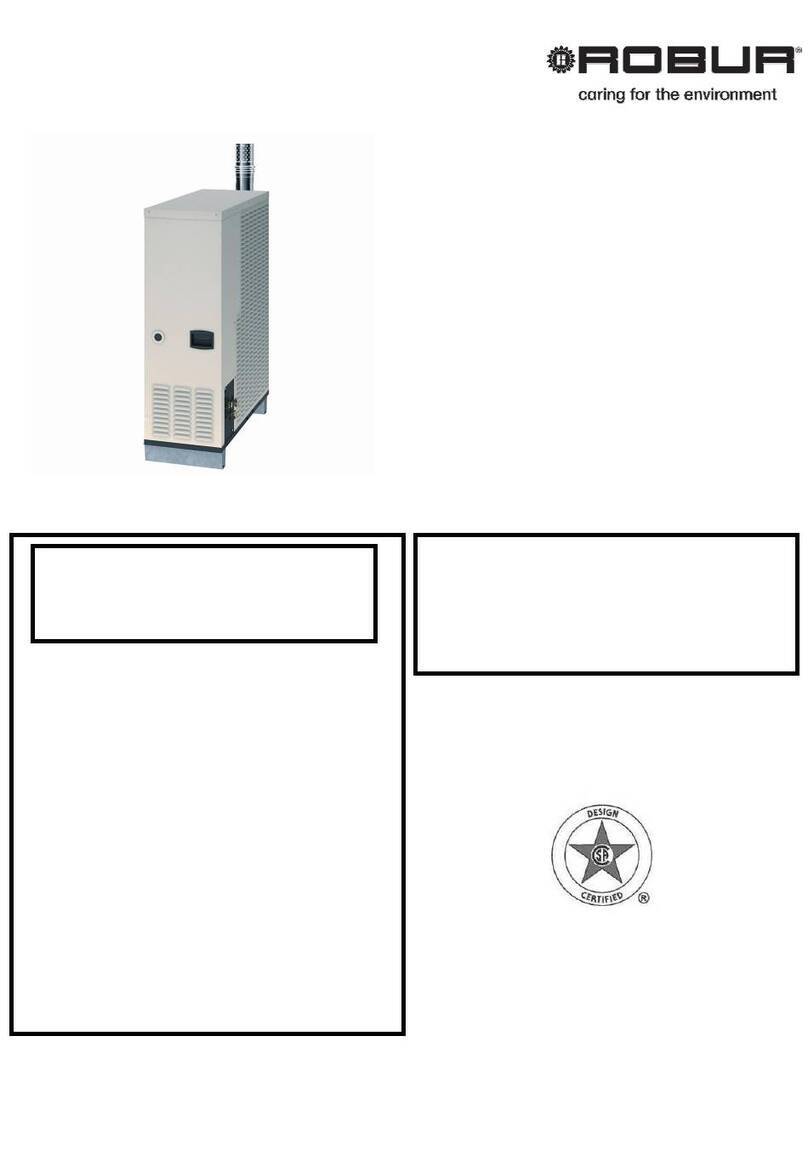
Robur Heaters Line F2 C Series Service manual

Heaters Line F2 Series C
Gas fired unit heaters
for heating medium-large areas
Natural gas/LPG fired
Installation, use and
maintenance manual

EDITION: 06/2011
Code: D-LBR552
This manual has been written and printed by Robur S.p.A.; the reproduction even partial
of this manual is forbidden.
The original is archived at Robur S.p.A.
Any use of this manual other than for personal consultation must be previously authorised
by Robur S.p.A.
The rights of those who have legitimately filed the registered trademarks contained within
this publication are not affected.
With the aim of continuously improving the quality of our products, Robur S.p.A. reserves
the right to modify instructions, drawings and data contained in this manual without prior
notice.

FOREWORD
Ed.06/2011 3
FOREWORD
This manual is intended for those people who need to install and use the Robur F2 C
Series Gas Fired Unit Heaters.
In particular this manual is addressed to the hydraulic installation technician who shall
install the generator, the electrical installation technician who shall connect the generator
to the power supply and the final user who shall check its normal working.
This manual is also addressed to the Technical Assistance Centres for the main service
operations.

Series F2 80 C
4Ed. 06/2011
Meaning of Icons
The icons placed on the right margin of the odd pages of this manual have the following meaning:
Danger signal
!Warning
Note
Start of operating procedure
Reference to another part of the manual or to another
manual/book
Table 1 – Descriptive Icons
Section 1 - Generality and Technical Characteristics
Section 2 - User
Section 3 - Hydraulic Installation Technician
Section 4 - Electrical Installation Technician
Section 5 - Maintenance and Servicing
Table 2 – Section Icons

TABLE OF CONTENTS
Ed.06/2011 5
TABLE OF CONTENTS
SEZIONE 1: GENERAL INFORMATION AND TECHNICAL CHARACTERISTICS..........7
1.1 GENERAL WARNINGS .......................................................................................................................7
1.2 OPERATION OF THE UNIT ................................................................................................................9
1.3 TECHNICAL CHARACTERISTICS....................................................................................................10
SAFETY AND CONTROL DEVICES ......................................................................................... 10
1.4 TECHNICAL CHARACTERISTICS....................................................................................................11
1.5 DIMENSIONS OF THE F2 C SERIES GAS FIRED UNIT HEATERS ...............................................12
SECTION 2: END USER ..................................................................................................13
2.1 FUNCTIONS OF THE REMOTE CONTROL KEYS ..........................................................................13
2.2 HOW TO TURN ON AND OFF THE HEATER ..................................................................................14
WINTER OPERATION (HEATING) ........................................................................................... 14
SWITCHING-OFF ...................................................................................................................... 15
SUMMER OPERATION (COOLING)......................................................................................... 15
SEASON SHUTDOWN.............................................................................................................. 15
SECTION 3: PLUMBING INSTALLER.............................................................................17
3.1 GENERAL HEATER INSTALLATION REQUIREMENTS..................................................................17
3.2 INSTALLATION SEQUENCE ............................................................................................................17
3.3 SIZE AND INSTALLATION OF THE AIR INLET/FLUE EXHAUST PIPES .......................................18
3.4 DUCTING SYSTEM PRESSURE DROP FOR DISTRIBUTION/INTAKE AMBIENT AIR .................30
SECTION 4: ELECTRICAL INSTALLATION TECHNICIAN ............................................33
4.1 HOW TO CONNECT THE HEATER TO THE POWER SUPPLY .....................................................33
4.2 HOW TO INSTALL THE ROOM THERMOSTAT ..............................................................................34
4.3 HOW TO INSTALL THE REMOTE CONTROL BOX.........................................................................35
SECTION 5: MAINTENANCE AND SERVICING .............................................................39
5.1 HOW TO ADJUST THE GAS VALVE................................................................................................39
5.2 HOW TO REPLACE THE GAS..........................................................................................................40
5.3 MAINTENANCE .................................................................................................................................42
5.4 FAULT LOCATION.............................................................................................................................42
5.5 FAULTS AND SOLUTIONS ...............................................................................................................43
Series F2 80 C
6Ed. 06/2011

GENERAL INFORMATION AND TECHNICAL CHARACTERISTICS
Ed.06/2011 7
SEZIONE 1: GENERAL INFORMATION AND TECHNICAL
CHARACTERISTICS
In this section you can find the general warnings to follow for the installation and use of
the F2 C Series heaters, a short description of the heater operation, design characteristics
and technical data.
1.1 GENERAL WARNINGS
This manual is an integral and essential part of the product and must be given to the final
user.
This appliance must be exclusively used for the purpose it was intended. Any other use is
to be considered improper and therefore dangerous.
The Manufacturer will not be held responsible for damages resulting from installation
errors or failure to comply with the Manufacturer’s instructions.
The appliance must be installed in compliance with the rules and regulations in force.
Do not obstruct the fan intake opening or the air delivery grids.
!
In case of failure and/or malfunction of the appliance, isolate the unit (disconnect it
from the power supply and close the main gas cock), do not attempt any repair or
direct servicing.
The Manufacturer’s Authorised Service Centres using only original spare parts
must only carry out any repair to the products.
The non-observance of the above-mentioned provisions may compromise the safety of
the unit.
To ensure unit efficiency and correct operation, it is essential that qualified service
engineers carry out annual maintenance following the Manufacturer’s instructions.
By the term Qualified Service Engineers it is meant the personnel having specific
technical skills in the field of heating system components for civil use. In any case for
more information please contact the Technical Assistance Office of ROBUR S.p.A.
(tel. +39 035/888111).
Should the unit be sold or transferred to another owner, please ensure that the manual
remains with the unit for use by the new owner and/or installer.
Before turning the heater on, a qualified service engineer must check:
- that electric and gas supply ratings are the same as those given in the data plate.
- that the exhaust duct operates correctly.
- that combustion air feed and exhaust occur correctly according to the existing
standards.
- the internal and external tightness of the fuel supply system.
- fuel flow control according to the heater power requirements.
- that the heater is supplied with the type of fuel for which it is pre-set.

Series F2 80 C
8Ed. 06/2011
- that the gas supply pressure is within rating limits.
- that the gas supply system is suitable to the heater and all safety and check-over
devices prescribed by existing standards are duly installed.
Do not use gas pipes to ground the appliance, or any other electrical appliances.
Avoid unnecessary supply when unit is not in use and always clock the main gas cock.
If the appliance is turned off for a longer time period, close the main gas supply cock and
cut off the power supply.
IF YOU SMELL GAS
!Do not operate electric switches, telephones and any other object or device
which may cause sparks.
!Shut-off the gas supply.
!Open immediately doors and windows to create a cross-current of air to purify
the room.
!Call for a qualified service engineer.

GENERAL INFORMATION AND TECHNICAL CHARACTERISTICS
Ed.06/2011 9
1.2 OPERATION OF THE UNIT
The F2 C Series gas fired unit heater is an independent heater appliance with airtight
combustion circuit and forced air draft.
It is designed for an indoor installation - inside the area to be heated.
It is adjustable for the use of Natural Gas (G20) and L.P.G. (G30/G31) (appliance
belonging to the II2H3B/P category according to the Standard EN 1020).
The combustion circuit is airtight regarding heated room and conforms the standard EN
1020 for the C type appliances: the air inlet of the combustion air and the flue exhaust are
outdoors and are ensured through the operation of combustion blower.
The heater operation is controlled by a room thermostat on demand (available as
accessory). When the thermostat is turned on the flame control box, after the pre-purge
period (about 40 seconds), ignites the burner.
The flame sensor controls the ignition of the burner. If the flame does not appear the
flame control unit locks out the heater.
The combustion products pass through the heat exchangers, the air flow given by the
centrifugal fan provides warm air to the room.
The fan control thermostat allows the axial-flow fan to start automatically only when the
heat exchangers are hot (after about 60 sec. from the flame detection or when the
temperature of 60°C is reached on the exchanger thermostat) and to turn off when they
are cold. This prevents cool air from being blown into the room.
If heat exchangers overheat due to malfunction, the temperature limit thermostat cuts off
the supply to the gas valve by setting the blower and the fan; should the temperature
increase further, the limit thermostat comes into operation causing the switching off of the
heater. The limit thermostat reset is manual.
!
After removing the cause of overheating, Qualified service engineers should carry
out resetting of the temperature.
Ahead of the burner the flue fan is installed which makes the air-gas mixture and forces
draft of the exhaust flues.
Ahead of the burner the flue fan is installed which makes the air-gas mixture and forces
draft of the exhaust flues.
In case of obstructions in the exhaust or intake duct or in case of blower malfunction, the
flame control box reduces automatically the combustion air and consequently the gas flow
rate. In case of obstructions or malfunction beyond the allowed limits, the differential
pressure switch closes the gas valve and consequently stops the fuel flow to the burner.
In the summer time it is possible to activate only the axial fan to provide pleasant and
refreshing air movement in the room (for more information see Paragraph “SUMMER
OPERATION (COOLING)” at page 15).

Series F2 80 C
10 Ed. 06/2011
1.3 TECHNICAL CHARACTERISTICS
The F2 C Series gas fired unit heaters are supplied with:
-Premix burner made of stainless steel
-High head blower
-Control board, with microprocessor and anti-noise filter, which manages the
following functions: burner ignition, flame monitor, blower speed control, fan/s
control, exchanger temperature control by thermostat
- Cylindrical combustion chamber made of stainless steel
-Heat exchangers, patented by ROBUR, made of special light alloy, fining
horizontally on the air side and vertically on the flue side with extremely high
capacity of thermal exchange
-Steel casing painted with epoxy powders
-Centrifugal fan/s with high air flow capacity.
SAFETY AND CONTROL DEVICES
-High temperature limit switch: 100 °C with manual reset (prevents the
overheating of the heat exchangers).
-Pressure differential switch: when the flue exhaust/air intake ducts are
obstructed, the appliance is stopped.
-Gas solenoid valve: in the case that one of the safety devices is activated (limit
thermostat, safety thermostat, etc.) the gas valve is electrically de-energised with
contemporary cut-off of the burner gas supply.
!Supply voltage: 230 V - 50 Hz
!Operating temperature: 0 °C to +60 °C
!Model: SIT 822 Novamix
-Ignition and flame control box: it controls the ignition and flame of the premix
burner; if there is flame not detected during the safety period the flame control
box will stop the appliance; with manual reset.
- Safety time: 5 seconds
- Pre-purge time: 40 seconds
- Power supply: 230 V - 50 Hz
- Model: Bertelli & Partners DIMS03 with ignition
transformer BRAHMA TC2LTCAF

GENERAL INFORMATION AND TECHNICAL CHARACTERISTICS
Ed.06/2011 11
1.4 TECHNICAL CHARACTERISTICS
MODEL U.M. F2 80 C
APPLIANCE CATEGORY II2H3B/P
APPLIANCE TYPE C13 - C33 – C53 – C63 - B23
FEED GAS Natural Gas - L.P.G.
NOMINAL HEAT INPUT kW 80
NOMINAL HEAT OUTPUT kW 73.6
NOMINAL GAS CONSUMPTION NATURAL GAS
(15° C – 1013 mbar) L.P.G. G30
L.P.G. G31
m3/h
kg/h
kg/h
8,47
6,31
6,22
RATED EFFICIENCY % 92
INLET GAS PRESSURE NATURAL GAS
L.P.G. G30
L.P.G. G31
mbar
20
30
30
GAS INLET DIAMETER “ ¾ F
INTAKE PIPE DIAMETER mm 80
EXHAUST PIPE DIAMETER mm 80
SUPPLY VOLTAGE 400 V 3 N – 50 Hz
WATTAGE kW 2,3
OPERATING TEMPERATURE (1) °C 0 / + 35°C
FUSE A 6,3
AIR FLOW (2) m3/h 8.500
AIR FLOW
(AT THE MAX LOSS PRESSURE) m3/h 5.800
MAX PRESSURE HEAD(3) Pa 250
TEMPERATURE RATE K 25,6 / 37,6
WEIGHT kg 165
Table 3 – Technical characteristics
1 WARNING: THE ROOM OPERATIONAL TEMPERATURE IS BETWEEN 0 °C AND +35 °C
THE APPLIANCE’S COMPONENTS OPERATIONAL TEMPERATURE IS BETWEEN 0 °C AND +60 °C
2AT 20 °C – 1013 mbar
3 FOR MORE INFORMATION ABOUT THE AVAILABLE PRESSURE HEAD PLEASE SEE PARAGRAPH 3.4 – DUCTING SYSTEM PRESSURE
DROP FOR DISTRIBUTION/INTAKE AMBIENT AIR AT PAGE 30.

Series F2 80 C
12 Ed. 06/2011
1.5 DIMENSIONS OF THE F2 C SERIES GAS FIRED UNIT HEATERS
Figure 1 – Dimensions of F2 80 C

END USER
Ed.06/2011 13
SECTION 2: END USER
In this section you can find all the necessary instructions for a correct operation of the F2
C Series gas fired unit heaters.
The operation of the F2 C Series gas fired unit heaters are governed by a room
thermostat (not supplied but available as accessory) and the remote control provided with
the heater (see Figure 2).
Here below you can find all the necessary instructions for the correct use of the remote
control.
2.1 FUNCTIONS OF THE REMOTE CONTROL KEYS
Figure 2 – Remote control
The remote control keys have the following functions:
- Key (A): SUMMER/WINTER SELECTION.
Allows to select the “Winter” or “Summer” operation.
Winter operating mode status ( ) for winter heating.
Summer operating mode status ( ) for summer cooling (the burner is off, ONLY
the fan/s is/are on).
- Key (B): RESET BUTTON.
Allows to resume normal operation of the heater.
Led (C): LOCKOUT/FAULT INDICATOR LIGHT ( ).( ).
Allows to signal the heater lockout condition and identify the fault (cause which
determines the lockout condition).
For reset instructions and anomaly detection refer to 5.4 FAULT LOCATION of page
42.
B
A
C

Series F2 80 C
14 Ed. 06/2011
2.2 HOW TO TURN ON AND OFF THE HEATER
!The heater must be turn on for the first time by qualified service engineers.
Before starting the heater, qualified service engineers must check that:
!the rating data are compatible with those of the gas and power supply lines;
!the calibration is compatible with the heater power;
!the flue exhaust duct is working properly;
!the combustion air intake and flue exhaust are carried out correctly according
to the existing standards.
WINTER OPERATION (HEATING)
To Have: the heater connected to the gas and power supply lines.
1 - Set the room thermostat to the maximum value.
2 - Open the main gas cock.
3 - Power the appliance by closing the 2-pole switch (to be supplied by the electrical
installation technician).
4 - Set the winter/summer key (A) of the remote control to the winter ( ) position (see
Figure 2 at page 13).
5 - After the pre-purge time (about 40 seconds), the gas solenoid valve opens and the
heater is turned on.
6 - If the flame is present, the control box keeps the gas valve open.
7 - Otherwise, the flame control box locks out the appliance by switching on the lock out
warning light C on the reset button B (see Figure 2 at page 13).
8 - When the condition at point 7 takes place, push the reset button B.
9 - If the heater is turned on correctly set the room thermostat to the desired value.
If the heater is switched on after a long period of inactivity or at the first start-up of
the appliance you may need to repeat several times the operation because there is
air in the pipes.

END USER
Ed.06/2011 15
SWITCHING-OFF
To Have: the heater connected to the gas and power supply lines.
10 - To turn off the heater set the room thermostat to the minimum value. The burner will
turn off, while fans will continue to work until the appliance is completely cooled.
!It is absolutely forbidden to turn off the heater by cutting the power off since this
operation can damage the appliance. If you cut the power to the heater the axial fans
stop working immediately and the limit thermostat is activated. This last shall be
reset manually.
In case of a long period of inactivity, after the above operation and after the axial
fans are turned off, close the main gas cock and cut out the power by means of the
2-pole switch placed on the power supply line.
SUMMER OPERATION (COOLING)
To Have: the heater connected to the gas and power supply lines.
1 - Close the main gas cock and energize the appliance by closing the 2-pole switch (to
be supplied by the electrical installation technician).
2 - Set the winter/summer key (A) of the remote control to the ( ) position (see Figure
2). In this way, with the burner off, ONLY the axial fan continues to work by moving
the ambient air.
SEASON SHUTDOWN
1 - Turn the appliance off (as described in the SWITCHING-OFF Paragraph) and wait
until the axial fans stop.
2 - Close the main gas cock upstream the appliance.
3 - If you do not need to use the SUMMER function, cut the power off to the appliance
by means of the 2-pole switch located on the power supply line.

Series F2 80 C
16 Ed. 06/2011

PLUMBING INSTALLER
Ed.06/2011 17
SECTION 3: PLUMBING INSTALLER
In this section you can find all the necessary instructions to install F2 C Series heaters
from the hydraulic point of view.
3.1 GENERAL HEATER INSTALLATION REQUIREMENTS
The installation shall be made, according to the Manufacturer’s instructions, by qualified
service engineers.
By Qualified Service Engineers we mean the personnel with specific technical
skills in the field of the heating system components. In any case, if you need more
information please contact the Pre-Sale Department of ROBUR S.p.A. (tel. +39
035/888111).
An incorrect installation can cause damages to people, animals and property. In case of
erroneous installation, the Manufacturer cannot be held responsible for such damages.
The installation must be performed in compliance with the existing national regulations.
For the installation it is necessary to respect the following instructions:
- Dimension the duct system and the warm air and intake air diffusers taking into
consideration the characteristics of air flow, head pressure of the centrifugal fan,
and type of pulley utilised.
- In order to obtain the maximum comfort and efficiency from the installation it is
suggested to respect the following rules:
!Be careful that the air blowing out from the diffusers do not invest directly the
people
!Take into consideration the presence of obstacles (i.e. pillars).
- It is not recommended the installation of F2 C series in greenhouses or ambient
with high rate of humidity or similar atmospheric conditions because these units
have not been designed for this type of installation.
3.2 INSTALLATION SEQUENCE
Install the gas supply lines, the electric power lines, as well as the flue exhaust openings
and the combustion air inlet according to the approved installation project.
1 - Unpack the unit carefully checking that it has not been damaged during transport;
every unit is factory tested before shipment, therefore, if there are damages report
them immediately to the carrier.
2 - Make sure that an adequate gas supply from an efficient gas network is provided,
particularly if the unit is supplied with:
Natural Gas
Be sure that the pressure of the gas network, with the unit in operation, is set at 20
mbar (204 mm H2O) (allowed tolerance between 17 mbar and 25 mbar).

Series F2 80 C
18 Ed. 06/2011
L.P.G. (Propane – Butane Mix)
For the first pressure drop required in the supply, it is advisable to install a pressure
regulator near the liquid gas tank so as to reduce the pressure to 1.5 bar. A pressure
regulator for a second pressure drop should be placed near the heater to reduce the
pressure from 1.5 bar to 30 mbar (306 mm H2O) (allowed tolerance between 20
mbar and 35 mbar).
L.P.G. (Pure Propane)
For the first pressure drop required in the supply, it is essential to install a pressure
regulator near the liquid gas tank so as to reduce the pressure to 1.5 bar. A pressure
regulator for a second pressure drop should be placed near the heater to reduce the
pressure from 1.5 bar to 30 mbar (306 mm H2O) (allowed tolerance between 20
mbar and 35 mbar).
!In case of doubt on the composition of the GPL used, adjust the appliance as for the
propane-butane mix.
3 - Connect the heater to the gas supply line by equipping the gas supply pipe with a
shut-off cock and a three-piece union.
4 - Connect the flue pipe to the flue exit of the heater and eventually the external air
pipe for the combustion with ring for air intake.
5 - Connect the flange of the heater to the duct for the distribution of the warm air and
the mixing chamber with eventual ducts previewed for the intake air external and/or
internal.
6 - Verify that the sum of the losses of the ducting system will be between the values
indicated in the Table 7 at page 31.
3.3 SIZE AND INSTALLATION OF THE AIR INLET/FLUE EXHAUST
PIPES
F2 C Series gas fired unit heaters can be installed as follows
-C13 type installation: room sealed combustion circuit appliance with inlet air
supply and outlet of exhaust gases, either separated (see Figure 3, Figure 4,
Figure 5, Figure 6 and Figure 7 starting from page 21). This type of installation is
sealed regarding the heated room.
-C33 type installation: room sealed combustion circuit appliance with inlet air
supply and outlet of exhaust gases, either separated or concentric ducts (see
Figure 8 at page 23) on the ROOF. This type of installation is sealed regarding
the heated room.
-B23 type installation: this appliance must be connected to a flew which draws the
exhaust gases to the outside, through a proper duct; while, the combustion air is
taken directly from the room. This exhaust flue duct can be either horizontal or
vertical. This type of installation is not sealed regarding the heated room (see
Figure 9, Figure 10, Figure 11, Figure 12, Figure 13 and Figure 14 starting from
page 24).

PLUMBING INSTALLER
Ed.06/2011 19
-C53 type installation: room sealed combustion circuit appliance with inlet air
supply and outlet of exhaust gases by using separated ducts on different WALLS
of the building and far the one from the other: for example, the air inlet duct from
the wall behind the appliance and the flue exhaust duct far from the appliance or
on the roof (see Figure 15, Figure 16, Figure 17, Figure 18 and Figure 19 starting
from page 27).
-C63 type installation: allows to install air inlet/flue exhaust systems, by using
certified ducts, elbows and terminals purchased on the market. Moreover, it
permits to use pipe diameters bigger than 80 mm: for example when the
installation requires using the pipe of the larger diameter, caused by the longer
ducts. With this typology, for the calculus of the flue/air inlet system refer to the
duct Manufacturer data and furthermore to the flue composition, flow and
temperature (see Table 4 at page 20).
In the case the flue pipe system is installed to the wall and the one of the intake air
of the centrifugal fan is installed outdoor on the same wall, it is OBBLIGATORY to
have the flue pipe system at a distance of 1,5 m at least from the external intake air
pipe, in order to avoid that the combustion products will return in the ambient
heated.
In any case, use only approved ducts for the installation of the units. Upon request,
ROBUR S.p.A. can supply approved rigid pipes, coaxial pipes and terminals.
To determine the correct size of the piping system, its total pressure drop has to be
calculated.
Data to calculate the pressure drop for the air intake/flue exhaust system supplied on
request by Robur SpA are in Table 5 and Table 6 at page 20.
External terminals pressure drops are negligible since they are very low.
During the project design phase it is necessary to verify that the total inlet/outlet pipes
pressure drops are lower than the maximum pressure drop allowed by the appliance (see
Table 4).
The maximum lengths of the air supply and flue exhaust ducts, for different types of
installation, are given from Figure 3 to Figure 19. The above-mentioned length values are
APPROXIMATE and only for standard installations where the air supply and flue exhaust
ducts follow a linear path as shown in the relevant figures. Otherwise, you need to
calculate pressure drops.
!When vertical flue pipes are installed, to prevent that condense drops enter the
extraction fan, on the base of the vertically mounted flue pipe a T-shaped piece must
be fitted in order to collect the condense.

Series F2 80 C
20 Ed. 06/2011
DATA TO CALCULATE THE PRESSURE DROP FOR AIR INTAKE/FLUE EXHAUST PIPES PURCHASED ON THE
MARKET
Flue CO2(%)
Mod. Texhaust fume
Temperature °C
Flue Flow
(Weight)
kg/h Natural Gas LPG
Maximum
Allowed Pressure
Drop (Pa)
F2 80 C 170 140 9,2 – 9,4 10,7 150
Table 4 – Data to calculate the pressure drop for air intake/flue exhaust pipes purchased on the market
DATA TO CALCULATE THE PRESSURE DROP FOR THE AIR INTAKE/FLUE EXHAUST SYSTEM WITH Ø 80 OR
Ø 100 PIPES SUPPLIED
Component pressure drop Ø 80 Component pressure drop Ø 110
pipe (Pa/m) elbow 90° (Pa) pipe (Pa/m) elbow 90° (Pa)
Mod.
flue air flue air flue air flue air
F2 80 C 20 15 26 20 6 2,4 10 6
Table 5 – Data to calculate the pressure drop for the air intake/flue exhaust system with Ø 80 or Ø 100 supplied on
request by Robur SpA
DATA TO CALCULATE AIR/FLUE SYSTEM WITH PIPES Ø 130
SUPPLIED ON REQUEST BY ROBUR S.P.A.
Component pressure drop Ø 130
pipe (Pa/m) elbow 90° (Pa) Coaxial (Pa)
Mod.
flue air flue air To the roof
(O-KTC001)
Condense loss
(Pa)
(O-SCR013)
F2 80 C 2,7 1,2 7 2 32 1,5
Table 6 – Data to calculate the pressure drop for the air intake/flue exhaust system with Ø 130 supplied on request by
Robur SpA
For each 45° elbow an increment of 1.2 m in length of the pipe on which it has been
installed should be added (e.g. if the 45° elbow has been mounted on an air intake
pipe, which is 2 m long, to calculate the pressure drop you should consider a total air
intake pipe length of 3.2 m).
Table of contents
Other Robur Heater manuals

Robur
Robur Calorio M User manual

Robur
Robur AY00-119 Series User manual

Robur
Robur Next-R User manual

Robur
Robur TS 2000 User manual

Robur
Robur Next-R Service manual

Robur
Robur Supercromo D-LBR167 Quick start guide

Robur
Robur 5001 User manual

Robur
Robur G 30 Service manual

Robur
Robur Supercromo User manual

Robur
Robur TS2000 Series User manual
Popular Heater manuals by other brands

BASETech
BASETech 2268546 operating instructions

EUROM
EUROM 332841 instruction manual

Dimplex
Dimplex CAB Series Installation and operating instructions

EOS
EOS Herkules XL S120 HD Installation and operating instructions

KASTOR
KASTOR KARHU-22 T Installation and user manual

MILL
MILL Invisible & Glass Series Assembly and instruction manual