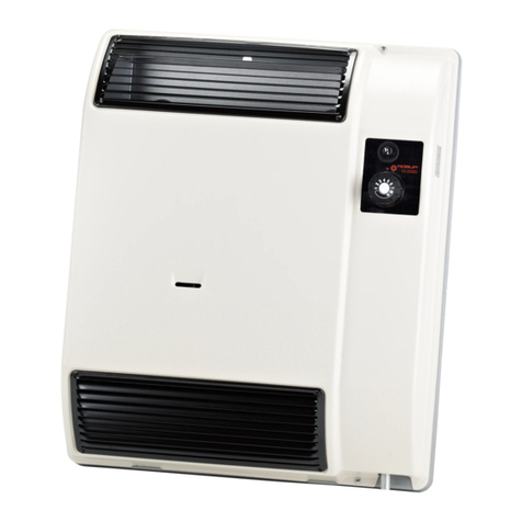
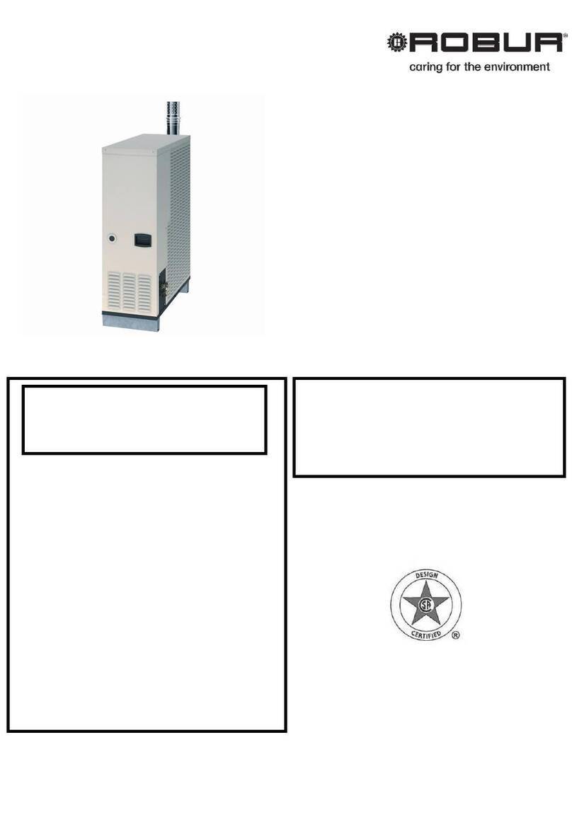
Robur 5001 User manual

Trouble shooting manual – Robur gas fired wall heater model 5001
Version 1.2 - 12/06/2006 1/21
GAS-FIRED WALL HEATER
MODEL “5001”
TROUBLE-SHOOTING AND SERVICE MANUAL

Trouble shooting manual – Robur gas fired wall heater model 5001
Version 1.2 - 12/06/2006 2/21
L1-L2: Electrical supply 120V – 60Hz; L1
phase, L2 neutral
M9: Main Fuse – 5x20 size – A
Z1: Reset switch
M2: Fan thermostat
M: Fan motor
Z9: Room thermostat
M1: Overheat thermostat
NP: Pressure switch
RP8: Flame sensor
RP7: Spark igniter
S: Combustion blower motor
EV: Gas valve
TR: 120/2 V transformer
SF: Flame view lamp (Green lamp)
SB: Lock-out lamp (Red lamp)

Trouble shooting manual – Robur gas fired wall heater model 5001
Version 1.2 - 12/06/2006 3/21
FUNCTIONAL DIAGRAM

Trouble shooting manual – Robur gas fired wall heater model 5001
Version 1.2 - 12/06/2006 4/21
ELECTRIC SCHEME (*
(*) 5001: Only one fan motor (V1)

Trouble shooting manual – Robur gas fired wall heater model 5001
Version 1.2 - 12/06/2006 5/21
ELECTRIC BOX
TR – 120/2 V Transformer
Part number: JTRS017
Ignition control box
Part number: JCNT019
NP – Pressure switch
Part number: JPRS010
Z9 – Room thermostat
Part number: JTLT005
Z1 – Reset switch Part number: N19800205
SF/SB – Green and red lamps
Part number: ELMP006 –
ELMP007

Trouble shooting manual – Robur gas fired wall heater model 5001
Version 1.2 - 12/06/2006 6/21
GAS ASSEMBLY
Gas burner + gas
nozzle
Part number:
JPRT010
Natural gas nozzle
LP gas nozzle
Part number: JGLL065
Part number: JGLL067
EV – Gas valve
Part number: JVLV065

Trouble shooting manual – Robur gas fired wall heater model 5001
Version 1.2 - 12/06/2006 7/21
COMPONENTS (1
S – Combustion
blower motor
Part number: JMTR017
M1 – Overheat
thermostat
Part number: JTLT006
M2 - Fan thermostat Part number:J12301018

Trouble shooting manual – Robur gas fired wall heater model 5001
Version 1.2 - 12/06/2006 8/21
COMPONENTS (2
RP8 : Flame sensor Part number:JLTT015
RP7: Spark igniter
(n.2 pcs)
Part number: JLTT023

Trouble shooting manual – Robur gas fired wall heater model 5001
Version 1.2 - 12/06/2006 9/21
COMPONENTS (3
Fan blades Part number: VVNT003-
VVNT002
M - Fan motor Part number: JMTR018

Trouble shooting manual – Robur gas fired wall heater model 5001
Version 1.2 - 12/06/2006 10/21
V = 120 V
Starting sequence (electrical
STEP 1
1. Check L1 – L2 (Supply 120 V, 60 Hz)
2. Check M9 (Main fuse)
TROUBLE-SHOOTING STEP 1
Point 1 (L1-L2 .
No voltage (120 V).
Check the electrical supply line, wirings and connections.
Point 2 (M9 .
Fuse damaged.
Check the electrical supply line and replace the fuse.

Trouble shooting manual – Robur gas fired wall heater model 5001
Version 1.2 - 12/06/2006 11/21
STEP 2
3. Check Z1 (Reset switch). The switch is closed if there is no
ignition block.
4. Check M2 (Fan thermostat). The thermostat is closed only when
its temperature is higher than 10 °F.
TROUBLE-SHOOTING STEP
Point 3 (Z1
Z1 is open and no ignition block.
Check wirings and connections. If everything is OK replace the switch.
Point 4 (M2 .
M2 is close and fan thermostat temperature lower than 10 °F.
Check wirings and connections. If they are OK replace the thermostat.

Trouble shooting manual – Robur gas fired wall heater model 5001
Version 1.2 - 12/06/2006 12/21
STEP 3
5. Check Z9 (Room thermostat). Close the thermostat by a
clockwise rotation.
6. Check M1 (Overheat thermostat, automatic reset). The
thermostat is closed @ T lower than 1 0 °F
7. Check S (Combustion blower motor).
TROUBLE-SHOOTING STEP 3
Point 5 (Z9 .
After a clockwise rotation the contact is still open. Check
wirings and connections. If they are OK and the room
temperature is cold replace the switch.
Point 6 (M1 .
M1 is open and fan thermostat temperature lower than 1 0 °F.
Check wirings, connections, gas pressure, fan motor.
Clean fan blades and air grids
If everything is OK, replace the thermostat.
Point 7 (S .
S motor does not run. Check voltage, wirings and connections.
If everything is OK, replace the motor.
V = 120 V
Close @ 104 °F
T < 104 °F V = 0 V
T > 104 °F V = 120 V
Open @ 140 °F

Trouble shooting manual – Robur gas fired wall heater model 5001
Version 1.2 - 12/06/2006 13/21
STEP 4
8. Check NP (Pressure switch).
9. Check electrical supply to flame control box (120 V)
10. Check TR (electrical transformer) (120V/2 V)
11. Check EV (gas valve EV) (120V)
12. Check RP7 (ignitions electrodes)
13. Check RP8 (flame sensor)
TROUBLE-SHOOTING STEP 4
Point 8 (NP .
The NP contact is open and air blower ON.
Check wirings and connections. Check and clean blower pipes.
Check and clean burner and flue gas pipe. Clean blower.
If everything is OK, replace the switch.
Point 10 (TR .
No inlet voltage (120 V).
Check 5 poles connector and control box.
If everything is OK, replace the connector.
No outlet voltage (2 V) during ignition.
Check wirings and connections.
If everything is OK, replace the transformer.
Point 11 (EV .
Valve is closed during ignition.
Check wirings, connections and voltage.
If everything is OK, replace the gas valve.
V = 120 V
V = 120 V
V = 24 V

Trouble shooting manual – Robur gas fired wall heater model 5001
Version 1.2 - 12/06/2006 14/21
Point 12 (RP7 .
No spark during ignition.
Check electrodes, wirings and connections.
If everything is OK, replace the flame control box.
Point 13 (RP8 .
No flame sensing with flame.
Check flame sensor, wirings and connections. Check gas pressure and
exhausted flue pipe.
If everything is OK, replace the flame control box.
Starting sequence (gas
1. Check and clean exhausted flue pipes;
2. Check and clean air blower and fan motor;
3. Check and clean burner and combustion chamber;
. Check and clean gas nozzle;
5. Check gas type;
6. Check supply gas line pressure (see the manual);
7. Check gas losses;
8. Set burner gas pressure (see the manual).
Main service operations (once a year

Trouble shooting manual – Robur gas fired wall heater model 5001
Version 1.2 - 12/06/2006 15/21
1. Clean fan blades
2. Clean air blower
3. Check and clean sylicone red pipes
. Check air flow switch

Trouble shooting manual – Robur gas fired wall heater model 5001
Version 1.2 - 12/06/2006 16/21
5. Clean and check exhausted flue pipe and air intake pipe
Check red O-R gasket (N-RNG003).
If it’s damaged, replace it
6. Check for gas leaks on all connections

Trouble shooting manual – Robur gas fired wall heater model 5001
Version 1.2 - 12/06/2006 17/21
7. Check and adjust gas pressure
Gas inlet pressure
(pipeline)
Gas burner pressure
adjustment
Gas manifold
pressure (burner)

Trouble shooting manual – Robur gas fired wall heater model 5001
Version 1.2 - 12/06/2006 18/21
Adapting to a different gas type
Adapting to another gas type must be performed by a qualified installer
If the type of the gas does not correspond to the type to be used (natural or LPG gas) by the unit, it must be converted and
adapted to the correct type of the gas.
It is necessary to do the following two operations.
1. Nozzle changing
1. Remove the screw indicated below.

Trouble shooting manual – Robur gas fired wall heater model 5001
Version 1.2 - 12/06/2006 19/21
Trouble shooting manual – Robur gas fired wall heater model 5001
Version 1.2 - 12/06/2006 19/21
Trouble shooting manual – Robur gas fired wall heater model 5001
Version 1.2 - 12/06/2006 19/21
Trouble shooting manual – Robur gas fired wall heater model 5001
Version 1.2 - 12/06/2006 19/21
&

Trouble shooting manual – Robur gas fired wall heater model 5001
Version 1.2 - 12/06/2006 20/21
2. Gas pressure checking and setting
See the values reported in the table below.
Table 2
GAS TYPE MINIMUM LINE GAS PRESSURE
BURNER GAS PRESSURE
NATURAL GAS 7.0 in.w.c. 3.1 in.w.c.
LPG 11.0 in.w.c. 10.6 in.w.c.
Table of contents
Other Robur Heater manuals

Robur
Robur G 30 Service manual

Robur
Robur Supercromo D-LBR167 Quick start guide

Robur
Robur Next-R Service manual

Robur
Robur Heaters Line F2 C Series Service manual

Robur
Robur AY00-119 Series User manual

Robur
Robur Supercromo User manual

Robur
Robur TS 2000 User manual

Robur
Robur TS2000 Series User manual

Robur
Robur Next-R User manual
Robur
Robur Calorio M User manual