Rocal ARc LD User manual

ROCAL
MANUFACTURAS S.A.
MANUFACTURAS ROCAL SA
Raval Sant Antoni, Nº 2
(08540) Centelles
Barcelona (Spain)
N.I.F.: A 58618380
INSERT
ARc LD/LI
76/96
MANUAL DE CARACTERISTICAS, INSTALACION Y FUNCIONAMIENTO
USER’S GUIDE ON CHARACTERISTICS, ASSEMBLY AND OPERATING
MANUEL DES CARACTERISTIQUES, INSTALLATION ET FONCTIONNEMENT
MANUAL CARACTERÍSTICAS E INSTALAÇÃO E OPERAÇÃO
MANUALE DI INSTALLAZIONE E FUNZIONAMENTO CON SPECIFICHE TECNICHE

1
El equipo de Rocal le da las gracias por depositar su confianza en
nosotros y elegir uno de nuestros productos, disfrute su compra.
Our full team in Rocal thanks you for your trust and confidence and for
choosing one of our products. Enjoy your purchase.
L'équipe de Rocal vous remercie pour votre confiance en nous et pour
choisir un de nos produits. Profitez de votre achat.
Il team di Rocal La ringrazia per la fiducia accordataci e per aver scelto
uno dei nostri prodotti. Ci auguriamo che il Suo acquisto possa darle molte
soddisfazioni.
Rocal equipe agradece a sua confiança e para a escolha de um dos nossos
produtos. Esperamos que sua compra vai dar-lhe muita satisfação.

2
ESPAÑOL
INDEX
1. CARACTERISTICAS.......................................................................................................................................................................3
1.1 Características técnicas.............................................................................................................................................................3
1.2 Detalle de los componentes de entrega.....................................................................................................................................3
1.3 Esquema de las medidas del aparato........................................................................................................................................3
2. REQUISITOS PREVIOS A LA INSTALACION................................................................................................................................4
2.1 Suelo..........................................................................................................................................................................................4
2.2 Conducto de salida de humos....................................................................................................................................................4
2.3 Tipo de aparato..........................................................................................................................................................................4
2.4 Nicho del hogar..........................................................................................................................................................................4
2.4.1. Aislamiento del aparato.....................................................................................................................................................4
2.4.2. Aislamiento del nicho de hogar..........................................................................................................................................4
2.5. Distancias de seguridad............................................................................................................................................................4
2.5.1. Distancias interiores del nicho de hogar............................................................................................................................4
2.5.2. Distancias exteriores .........................................................................................................................................................4
2.7. Ventilación ................................................................................................................................................................................4
2.7.1. Ventilación del nicho de hogar...........................................................................................................................................4
2.7.2 Aportación de aire...............................................................................................................................................................4
2.8 Modificaciones del aparato ........................................................................................................................................................5
3. INSTALACION.................................................................................................................................................................................5
3.1 Proceso de instalación...............................................................................................................................................................5
4. USO Y FUNCIONAMIENTO ............................................................................................................................................................5
4.1 Combustibles autorizados por el fabricante ...............................................................................................................................5
4.2 Primeros encendidos. ................................................................................................................................................................5
4.3. Control de la combustión. .........................................................................................................................................................5
4.3.1. Registro primario ...............................................................................................................................................................5
4.3.2. Registro secundario...........................................................................................................................................................5
4.4 Encendido..................................................................................................................................................................................5
4.5 Carga y recarga de combustible ................................................................................................................................................5
4.6 Apertura de la puerta .................................................................................................................................................................6
4.7 Funcionamiento en condiciones climatológicas adversas..........................................................................................................6
4.8 Prevención de incendio..............................................................................................................................................................6
5. INSTALACION ELÉCTRICA ...........................................................................................................................................................6
5.1 Componentes.............................................................................................................................................................................6
5.2 Esquemas eléctricos..................................................................................................................................................................6
5.2.1 Esquema eléctrico funcionamiento con 2 turbinas..............................................................................................................6
5.2.2 Esquema eléctrico funcionamiento con 2 turbinas..............................................................................................................7
5.3. Función.....................................................................................................................................................................................7
5.4. Uso y mantenimiento ................................................................................................................................................................7
6. MANTENIMIENTO Y LIMPIEZA......................................................................................................................................................7
6.1 Mantenimiento............................................................................................................................................................................7
6.1.1 Bloqueo de mecanismos ....................................................................................................................................................7
6.1.2. Recambios.........................................................................................................................................................................7
6.2. Limpieza....................................................................................................................................................................................8
6.2.1 Cristal .................................................................................................................................................................................8
6.2.2 Extraccion de cenizas.........................................................................................................................................................8
6.2.3. Conducto de humos...........................................................................................................................................................8
6.2.4. Pintura. ..............................................................................................................................................................................8
7. ELEMENTOS OPCIONALES ..........................................................................................................................................................8
8. PROBLEMAS: CAUSA Y SOLUCIÓN ............................................................................................................................................9
9. ETIQUETA CE ...............................................................................................................................................................................10
Este manual consta de dos documentos, el documento I: MANUAL DE CARACTERISTICAS, INSTALACION Y
FUNCIONAMIENTO y el documento II: ANEXO. El documento ANEXO contiene todos los esquemas e imágenes
referidas en este documento.
ATENCIÓN: ES MUY IMPORTANTE QUE ANTES DE PROCEDER A LA INSTALACIÓN Y PUESTA EN
MARCHA DEL APARATO LEA Y SIGA LAS INSTRUCCIONES DE ESTE MANUAL.
3
1.1 Características técnicas
*Valores obtenidos en el laboratorio de Manufacturas Rocal
1.2 Detalle de los componentes de entrega
(Compruebe que dispone de todos los componentes descritos a continuación en relación a la imagen del
apartado II del documento ANEXO)
1. Cuerpo de la chimenea.
2.
A
erosol pintura anticalórica para retoques.
3. Parrilla de brassas.
4. Manopla antitérmica.
5. Gamuza para limpieza del cristal
y
marco frontal.
6. Kit entrada de aire exterior. (Conector entrada de aire exterior, soporte para el conector, junta tubular, anclajes
metálicos, tornillos
y
tuercas
)
.
7. Herramienta para la manipulación de los re
g
istros
y
apertura de puertas.
8. Sobre con 3 documentos: manual de características, instalación
y
funcionamiento,
y
ho
j
a de
g
arantía
1.3 Esquema de las medidas del aparato
Consulte documento ANEXO apartado I página 1.
Parámetro Modelo
A
Rc 76 LD/LI ARc 96 LD/LI
Tiro mínimo
–
máximo 11-13 Pa
Consumo de combustible 2,6 kg/h 4 kg/h
Caudal másico de los humos 10,8 g/s 16,7 g/s*
Rendimiento 85 % >75%*
Potencia nominal 10 kW 16 kW*
Rango de potencia 7
–
12 kW 11 - 19 kW
Concentración de CO medio
al 13% de O2
0.15%
<0.13%*
Concentración de partículas 39,13 mg/Nm3****
Tiro medio (ensayo) 12 Pa 12 Pa
Peso neto 161 kg 187 kg
Carga Máxima Autorizada 4 kg 5 kg
A
ltura recarga 200 mm 200 mm
Longitud leños 450 mm 600 mm
A
ltura mínima del conducto 4000 mm
Ø Conducto salida humos 180 mm 180 mm
Ø Entrada aire exterior 100 mm
Ø Conductos salida aire 120 mm
Distancia exterior (frontal)
1000 mm
1000 mm
Distancia exterior (Laterale cristal)
1000 mm
1000 mm
Distancia exterior (Lateral)
200 mm
500mm
Distancia exterior (Posterior)
200 mm
Ventilación en nicho de hoga
r
(entrada-salida)
450 cm2
Cableado eléctrico de conexión Manguera de silicona de 3 hilos de 1,5 mm2
Flujo aire turbinas (unidad) 135 m3/h
Potencia turbinas (unidad) 20 W
Turbinas instaladas 2 4
Distancia seguridad mín. a las salidas
de aire
250 mm
Temperatura media de humos 166º C 202ºC
Tipo de combustión INTERMITENTE
Conducto NO COMPARTIDO
Combustible LEÑA NATURAL
Humedad leños combustible 12-20 % - 2 AÑOS BAJO CUBIERTO
A
ño Certificación 2017
Nº de Certificado 17/14327-1028 ****
1. CARACTERISTICAS

4
TODAS LAS REGLAMENTACIONES LOCALES, INCLUIDAS LAS QUE HACEN REFERENCIA A NORMAS
NACIONALES O EUROPEAS HAN DE CUMPLIRSE CUANDO SE INSTALA EL APARATO.
ES NECESARIO QUE LA INSTALACION SEA REALIZADA POR UN PROFESSIONAL. EL NO CUMPLIMIENTO DE
ESTA CLAUSULA EXIME AL FABRICANTE DE CUALQUIER RESPONSABILIDAD.
2.1 Suelo. Asegúrese que el suelo donde colocará el aparato tiene la suficiente capacidad portante para soportar el
peso. De no ser así, debe realizarse una placa de reparto de la carga para una distribución equitativa del peso del
aparato. En caso de duda consulte a un especialista.
2.2 Conducto de salida de humos. Es obligatorio un conector de humos estanco desde la conexión del tubo del
aparato hasta el exterior y debe respetarse el diámetro de la salida de humos indicada por el fabricante. El buen estado
e idoneidad de esta salida deberá estar certificada por un profesional y también debe respetar la normativa
vigente del país. Este conducto no debe ser compartido con otros aparatos (véase tabla del punto 1.1 Características
técnicas).
2.3 Tipo de aparato.La chimenea es de tipo exenta por lo que no requiere revestirse de ningún material, puede ser
revestido si el usuario lo prefiere. Hogar con placas de vermiculita en el fondo, laterales y placa deflectora. Parrilla
brasas, bandeja cenizas y conjunto ventilación eléctrico incorporado. El aparato viene listo para instalar. El aparato
viene listo para instalar. Puede desmontarse todo el interiorsi se desea, para hacer más fácilsu transporte y colocación.
Es posible revestir el parato si se desea. En caso de revestirlo deberá aislarlo tal y como describe en el punto 2.4 Nicho
del hogar.
2.4 Nicho del hogar. El nicho de hogar debe construirse con materiales incombustibles y no debe descansar encima
del aparato ni en los puntos de contacto (como por ejemplo el marco frontal). Es necesario prever desde el interior de
la boca, una salida para el cable eléctrico. En su interior no debe contener materiales inflamables ni frágiles tales
como madera, papel pintado, cristal, papel enyesado, etc.).
2.4.1. Aislamiento del aparato. Es aconsejable revestir el aparato con placas aislantes (clase A 1, EN13501-1) en
sus laterales, parte trasera y parte superior.
2.4.2. Aislamiento del nicho de hogar. Es conveniente revestir con placas aislantes (Clase A-1, EN13501-1) las
paredes interiores del nicho de hogar.
2.5. Distancias de seguridad.
2.5.1. Distancias interiores del nicho de hogar.
2.5.2. Distancias exteriores. Cualquier elemento frágil o inflamable (textiles, electrónicos, madera, papel pintado,
cristal, papel enyesado, etc.) debe separarse del hogar respetando las distancias que se describen en la tabla I:
Características técnicas. Hay que tener especial atención en aquellas chimeneas con repisas de madera o similares:
hay que prevenir y evitar la posibilidad de que el aire caliente que expulsa el aparato incida directamente en la madera,
en ese caso se deberá aislar debidamente.
2.7. Ventilación. Es imperativo que en caso de revestir el aparato el nicho donde se instale disponga de ventilación.
2.7.1. Ventilación del nicho de hogar. Se debe prever la colocación de difusores de ventilación en el nicho de hogar
tanto para la entrada como para la salida. Véase la sección mínima que se recomienda es de 450 cm2.
2.7.2. Opciones para la salida del aire forzado: (Distancia seguridad mínima. a las salidas de aire 250 mm)
-SIN conexión tubos salidas de aire. Imagen III-1 de la página 3 del documento anexo. Se realiza solo la
conexión de salida de humos. NO se utilizan las salidas de aire superiores. El aire de la recámara del aparato
solo sale por la parte frontal del mismo.
2. REQUISITOS PREVIOS A LA INSTALACION
50 mm
1000 mm
1000 mm
50 mm 1000 mm
50 mm
50 mm
1000 mm
LI
LD
5
-CON conexión tubos salidas de aire. Imagen III-2 de la página 3 del documento anexo. Si se desea se puede
conducir el aire de la recámara del aparato a la parte superior del recinto de chimenea o a una habitación
contigua.
2.7.3 Aportación de aire. Debe prever una aportación de aire a la sala donde se ubique el aparato, especialmente es
importante cuando no se utiliza una entrada de aire exterior y también cuando se abre la puerta para realizar la recarga
de la leña. Esta entrada no puede ser inferior a 225 cm2. También tenga en cuenta el funcionamiento simultáneo con
otros aparatos de ventilación y/o calefacción tales como extractores de aire, bomba de calor, etc. En estos casos debe
compensarse la extracción con la correspondiente entrada de aire exterior.
2.8 Modificaciones del aparato. Cualquier modificación que se pretenda en el aparato debe estar autorizada por
escrito por Manufacturas Rocal SA. Es recomendable, además, utilizar únicamente las piezas de repuesto originales o
recomendadas por Manufacturas Rocal SA.
3.1 Proceso de instalación. Para proceder a la instalación siga los pasos detallados en el Apartado III del documento
ANEXO. ATENCIÓN: El deflector debe ajustarse en caso de exceso de tiro, para proceder siga los pasos: ”D.9”, “D.10”,
“D.11” y ”D.12”. Para ajustar el cierre de la puerta siga los pasos “D.15” al “D.16”.
4.1 Combustibles autorizados por el fabricante. El aparato no debe utilizarse como incinerador y están prohibidos
otros combustibles a los autorizados por el fabricante, incluidos líquidos o geles de encendido. Como combustible solo
se autoriza el uso de leños de madera naturales y no es recomendable el uso de maderas resinosas.
4.2 Primeros encendidos. Durante un tiempo prudencial, aproximadamente unas 24 horas, no debe superar un 50%
de la C.M.A (carga máxima autorizada por el fabricante). Antes de encender el fuego compruebe que dentro de la
cámara de combustión noha quedado ninguno de los elementos subministrados con la entrega del aparato (tales como
guantes, espray pintura…)
4.3. Control de la combustión. El aparato dispone de mecanismos para regular la combustión:
4.3.1. Registro primario. El registro primario se utiliza para controlar el aire que entra en la cámara de combustión por
la base del fuego. El registro primario debe usarse principalmente para el encendido y de ser necesario, como ayuda a
la combustión. Para localizar la maneta de control del registro, conocer el funcionamiento consulte la imagen “D.2” de
la página 7 del documento ANEXO. Si el combustible és de baja calidad se puede ajustar el recorrido del registro
primario siguiendo los pasos: “D.22” al ”D.25”. Si el problema persiste aporte aire por la parrilla de brasas siguiendo los
pasos “D.22” y ”D.26”.
4.3.2. Registro secundario. Elregistro secundariose utilizapara controlarel aire que entraen la cámarade combustión
por la parte superior. El registro secundario debe usarse principalmente para ajustar el grado de combustión. Para
localizar la maneta de control del registro y conocer su funcionamiento consulte la imagen “D.3” de la página 7 del
documento ANEXO.
4.4 Encendido. Para encender el fuego utilice materiales adecuados para ello tales como pastillas de fuego, papel y
ramas secas y finas. NO UTILICE GASOLINAS, DISOLVENTES O ALCOHOL. Para ver la posición correcta vea la
imagen “D.4” de la página 9 del documento ANEXO, a continuación, prenda lumbre. Mantenga los registros abiertos y
la puerta ajustada durante un tiempo prudencial, asi evitará la condensación en la puerta. Una vez este el fuego
encendido y el aparato suficientemente caliente cierre la puerta, ajuste el registro primario para evitar una combustión
excesiva y controle la intensidad del fuego mediante el registro secundario.
4.5 Carga y recarga de combustible. No debe superarse la C.M.A (carga máxima autorizada) ni en la carga ni en la
recarga. (Véase tabla de Características técnicas).
NOTA IMPORTANTE: -Las piezas de vermiculita interiores NO DEBEN RECIBIR GOLPES cuando
se efectúa la recarga de combustible.
-Si alguna de estas piezas se agrieta, pero está debidamente colocada en su
sitio, NO ALTERA EL FUNCIONAMIENTO CORRECTO DEL APARATO NI
COMPORTA RIESGO ALGUNO. El aparato puede utilizarse con total
normalidad. Estas grietas no suponen ningún defecto de fabricación por lo
que NO ENTRAN EN GARANTIA.
4. USO Y FUNCIONAMIENTO
3. INSTALACION
ATENCIÓN: - Debe respetarse la carga máxima autorizada por el fabricante, la medida de los leños así
como la altura de la recarga.
- No toque ni manipule ninguna parte del aparato cuando esté en marcha sin la protección
de la manopla térmica.
6
4.6 Apertura de la puerta. Debe abrirseúnicamente para efectuar la recarga. Para su apertura siga los pasos descritos
en las imágenes “D.1” de la página 9 del documento ANEXO.
4.7 Funcionamiento en condiciones climatológicas adversas. Es posible que el aparato funcione de forma
incorrecta debido a cambios climatológicos bruscos o inesperados, estos pueden provocar: bajas presiones o reflujos
de las corrientes de aire al interior del conducto de humos. Cuando se observen estos fenómenos es recomendable
cerrar los registros de aire de la combustión y dejar apagar el aparato.
4.8 Prevención de incendio. No debemos acercar ningún elemento inflamable a menos de la distancia de seguridad
descrita en la tabla del apartado 1.1 Características técnicas. Tomar especial precaución con la presencia de niños y
ancianos. En caso de incendio aparte todas las personas de su alrededor, si es posible cierre los registros al máximo y
avise al Servicio de Extinción de incendios.
TODAS LAS REGLAMENTACIONES LOCALES, INCLUIDAS LAS QUE HAGAN REFERENCIA A NORMAS
NACIONALES O EUROPEAS HAN DE CUMPLIRSE CUANDO SE CONECTA EL APARATO A LA RED ELÉCTRICA.
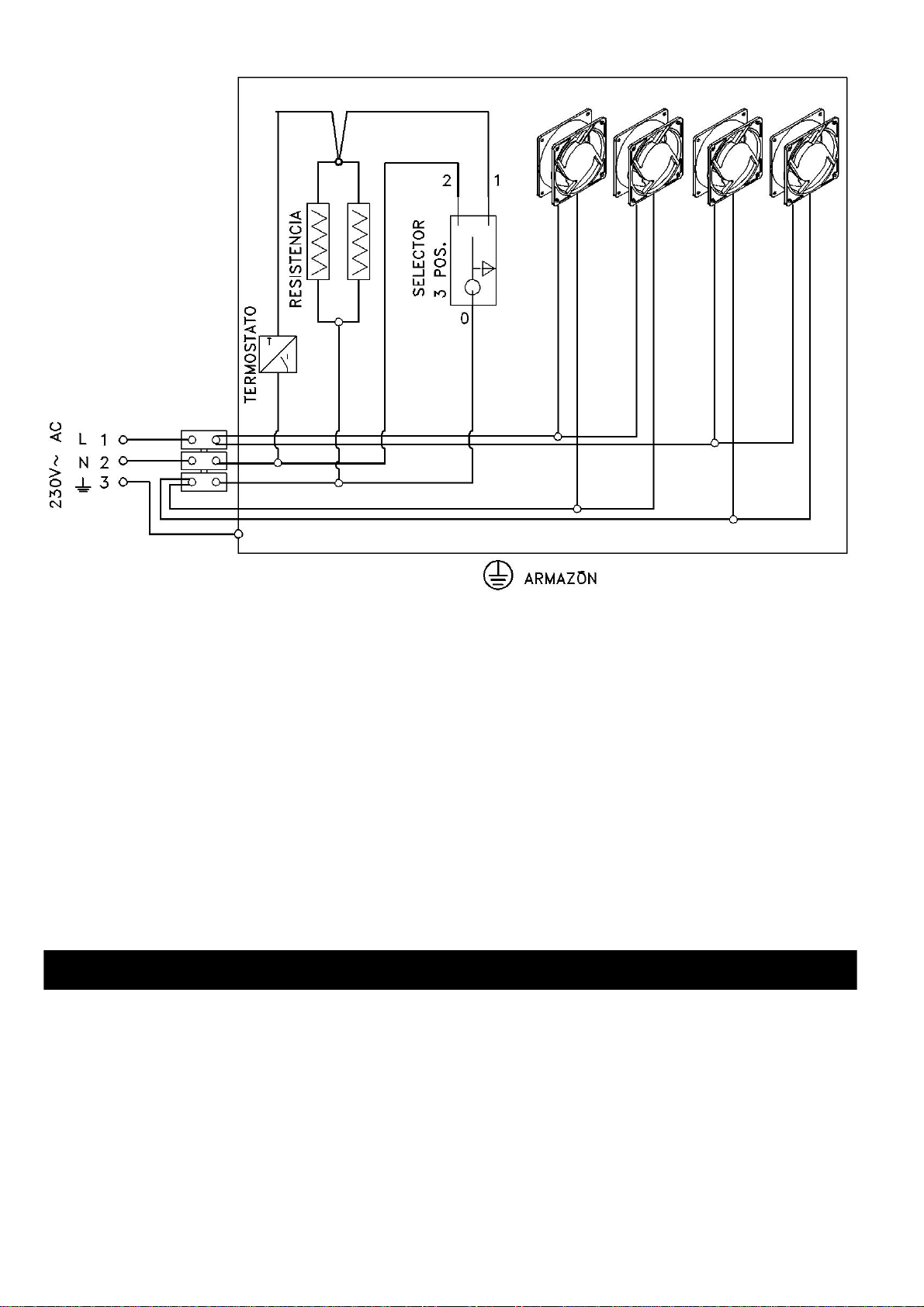
5.1 Componentes. El aparato viene equipado con dos turbinas helicoidales para el modelo ARc 76 LD/LI Graffiti y con
cuatro para el modelo ARc96 LD/LI Graffiti, termostato para la puesta en marcha de las turbinas, resistencia, interruptor
de control velocidad turbinas, cableado interior y manguera de silicona para la alimentación. Para recambios consulte
el apartado V del documento ANEXO.
5.2 Esquemas eléctricos
5.2.1 Esquema eléctrico funcionamiento con 2 turbinas
5. INSTALACION ELÉCTRICA
7
5.2.2 Esquema eléctrico funcionamiento con 4 turbinas
5.3. Función. El conjunto de ventilación sirve para impulsar el aire tomado de las rejillas inferiores del aparato y
expulsarlo, una vez calentado, por la parte frontal y/o los difusores de la parte superior.
5.4. Uso y mantenimiento. El conjunto de ventilación debe estar permanentemente conectado a la red eléctricacuando
el aparato está encendido.
El interruptor ofrece tres posibilidades:
-Posición 0: Velocidad lenta. El arranque y paro de las turbinas es automático mediante el termostato.
-Posición I: Velocidad rápida. El arranque y paro de las turbinas es automático mediante el termostato
-Posición II: Velocidad rápida. Manualmente (sistema manual y sin paro automático).
Después de un periodo de parada prolongada y antes de poner el aparato en marcha, es necesario comprobar el buen
funcionamiento de las turbinas y limpiar toda la suciedad de las rejillas frontales de la toma de aire. (Es conveniente,
además, que un profesional cualificado revise toda la instalación eléctrica del aparato).
ATENCIÓN:
Si el cable de alimentación está dañado debe ser sustituido por el servicio postventa o personal cualificado
similar con el fin de evitar un peligro.
6.1 Mantenimiento. Un mantenimiento adecuado y frecuente tanto del aparato como de la instalación contribuye en
gran medida a su buen funcionamiento. Es importante realizar un control periódico y completo del aparato así como de
los conductosy la instalación.De este modo, para suseguridad yconfort, algunos de nuestros distribuidores ofrecen
un contrato de mantenimiento del aparato. Contacte con su distribuidor para solicitar este servicio.
6.1.1 Bloqueo de mecanismos. Es necesario comprobar la ausencia de bloqueo de todos los mecanismos (registros,
puerta, entrada de aire exterior, etc.) después de un período prolongado de parada.
6.1.2. Recambios. Utilice únicamente las piezas de repuesto originales o recomendadas por manufacturas Rocal S.A.
Véase la imagen de la página 11 del documento ANEXO.
6. MANTENIMIENTO Y LIMPIEZA

8
6.2. Limpieza. Es importante que el aparato esté limpio de residuos para que todos sus mecanismos funcionen
correctamente. Para la limpieza del cristal y el marco frontal, utilice la gamuza seca que se suministra con la
chimenea u otra similar. No utilice líquidos ni productos de limpieza común.
6.2.1 Cristal. Para limpiar el cristal, hágalo con el aparato apagado. El líquido usado no debe entrar en contacto con
las partes metálicas de la puerta ni la junta cerámica, debido a la agresividad de estos productos puede iniciarse un
proceso de corrosión del aparato. Para reemplazar el cristal siga los pasos descritos en las imágenes “D.21” y “D.22”
del documento ANEXO.
6.2.2 Extraccion de cenizas. Vacíe el aparato solamente cuando esté completamente apagado, cuidando de que las
cenizas no contengan aun brasas encendidas; en tal caso debe depositarlas en un cubo metálico.
6.2.3. Conducto de humos. Es importante mantener limpio de residuos el conducto de evacuación de humos. Este
se ensucia en función del combustible utilizado, la marcha más o menos lenta de la combustión, etc. Es necesario
limpiar el conducto de humos al menos una vez por temporada.
6.2.4. Pintura. La pintura anticalórica que reviste el interior y exterior del aparato soporta hasta 600ºC de temperatura
y desprende un ligero olor característico que desaparece con los primeros encendidos.
Es posible que, en algunas zonas del interior del hogar, después de un tiempo de uso, la pinturaacabe por desaparecer,
debido a la corrosión por líquidos, tipos de combustibles inadecuados u otros que los autorizados por el fabricante, etc.,
en ese caso será necesario repintar todas las zonas dañadas antes de un período prolongadode parada. (Utilice única
y exclusivamente el aerosol “Rocal pintura anticalórica).
Rocal pone a su disposición diversos elementos opcionales, contacte con su distribuidor local para adquirir dichos
elementos. A continuación se muestra algunos de los elementos:
Elemento Códi
g
o Descripción
ECOntrol C7000 Re
g
ulador inteli
g
ente de la combustión
Leñero C1000
A
spirador de cenizas
A
SPIRADOR
Connector salida aire caliente
Difusor de 1 entrada D0001
Difusor de 1 entrada estrecho D0002
Difusor de 2 entradas D0006
Difusor de 2 entradas estrecho D0007
Difusor de 3 entradas D0011
Difusor de 4 entradas D0016
Difusor de 1 salida D1001
Difusor de 1 salida estrecho D1002
Difusor de 2 salidas D1006
Difusor de 2 salidas estrecho D1007
Difusor de 3 salidas D1011
Difusor de 4 salidas D1016
7. ELEMENTOS OPCIONALES

9
A continuación les mostramos una tabla con las posibles anomalías, sus causas y los remedios que debe seguir:
PROBLEM
A
CAUS
A
SOLUCION
1. Revoca humo y/o tiro
insuficiente Conducto incorrecto
Falta de aire de alimentación para la
combustión
Posición incorrecta de los registros
Suciedad del conducto
Revisión del conducto:
-conexión
-diámetro
-fugas en su trayecto
-longitud insuficiente
-salida al exterior
-posibles elementos que obstruyan la salida
Revisar conductos de ventilación y/o entrada de
aire exterior.
Funcionamiento simultaneo con otros aparatos de
ventilación y/o calefacción
Ajustar el registro
Contacte con un profesional para una limpieza de
este. Si el problema persiste contacte con su
distribuidor.
2.Cristal excesivamente
sucio Conducto incorrecto
Combustible inadecuado
Registros excesivamente cerrados
Revisar apartado insuficiencia de tiro (situado más
abajo).
Utilizar combustible recomendado
Ajustar los registros
3. Blanqueamiento del
cristal o pérdida del color
de la chapa
Exceso de temperatura causado por un fuego
excesivo en la cámara de combustión Revise la carga de combustible evitando el exceso
de temperatura.
Ajuste los registros
4. Calienta poco
Combustible inadecuado
Carga insuficiente
Registros del control de la combustión en una
posición incorrecta
Utilizar combustible recomendado
Añadir combustible
Ajustar los registros
5. Salida de humos y/o
gases por el frontal, malos
olores
Primeros encendidos
Elementos combustibles o inflamables en el
recinto o paredes circundantes al aparato
Grieta en la cámara de Combustión del
aparato
Esperar que el proceso de polimerización de la
pintura finalice, esto puede tardar de uno a varios
encendidos
Revisión de materiales aislantes tales como fibra
de vidrio, maderas ignífugas o posibles elementos
combustibles y substituirlos.
Comprobar su estanqueidad y si se descubre una
grieta contacte con el distribuidor
6. Exceso de tiro Conducto incorrecto
Registros de control de la combustión en una
posición incorrecta
Revisión del conducto
- longitud excesiva
- comprobar depresión
- diámetro incorrecto
- comprobar junta de la puerta
8. PROBLEMAS: CAUSA Y SOLUCIÓN

10
* Valores obtenidos en el laboratorio de Manufacturas Rocal
ARc 76 LD Graffiti M5952 ARc 76 LI Graffiti M5953
Nº CEE ----- Nº CEE -----
UNE-EN 13229
Aparato insertable para combustibles sólidos
500 mm
1000 mm 500 mm
1000 mm
UNE-EN 13229
Aparato insertable para combustibles sólidos
500 mm
500 mm 1000 mm
1000 mm
Concentración CO al 13% de O2: <0.13%*
Potencia térmica: 12 kW*
Rendimiento: >75 %*
Concentración partículas: ** mg/Nm3
Temperatura de humos: 204º C
Combustible: Leña natural
Concentración CO al 13% de O2: <0.13%*
Potencia térmica: 12 kW*
Rendimiento: >75 %*
Concentración partículas: ** mg/Nm3
Temperatura de humos: 204º C
Combustible: Leña natural
------- -------
MANUFACTURAS ROCAL SA
Raval Sant Antoni, 2
–
08540 Centelles
(
BCN
–
Spain
)
MANUFACTURAS ROCAL SA
Raval Sant Antoni, 2
–
08540 Centelles
(
BCN
–
Spain
)
ARc 96 LD Graffiti M5955 ARc 96 LI Graffiti M5956
Nº CEE ----- Nº CEE -----
UNE-EN 13229
Aparato insertable para combustibles sólidos
500 mm
1000 mm 500 mm
1000 mm
UNE-EN 13229
Aparato insertable para combustibles sólidos
500 mm
500 mm 1000 mm
1000 mm
Concentración CO al 13% de O2: < 0,13%*
Potencia térmica: 16 kW*
Rendimiento: >75 %*
Concentración partículas: ** mg/Nm3
Temperatura de humos: 202º C
Combustible: Leña natural
Concentración CO al 13% de O2: < 0,13%*
Potencia térmica: 16 kW*
Rendimiento: >75 %*
Concentración partículas: ** mg/Nm3
Temperatura de humos: 202º C
Combustible: Leña natural
------- -------
MANUFACTURAS ROCAL SA
Raval Sant Antoni, 2
–
08540 Centelles
(
BCN
–
Spain
)
MANUFACTURAS ROCAL SA
Raval Sant Antoni, 2
–
08540 Centelles
(
BCN
–
Spain
)
9. ETIQUETA CE

11
La etiqueta de Marcado CE está situada en la puerta del aparato. Ésta etiqueta contiene los datos técnicos, así
como el Nº de O.F. (este número también lo encontrará en la hoja de garantía). ESTE NÚMERO ES
IMPRESCINDIBLE PARA PODER SOLICITAR PIEZAS DE RECAMBIO.
La revisión del aparato así como la instalación y los conductos, es necesario que sea realizada por un profesional.
Para cualquier duda sobre lo aquí descrito, consulte con su distribuidor Rocal.
ATENCIÓN:
- Todas las pruebas han sido realizadas siguiendo la Normativa UNE-EN 13229:2002 -
UNE-EN13240:2002-A2:2005-AC:2006-A2:2005/AC:2007 - UNE-EN 60335
- La revisión del aparato, así como la instalación y los conductos, debe realizarla un
profesional.
- Para cualquier duda sobre lo aquí descrito, consulte con su distribuidor Rocal.
- EL INCUMPLIMINTO DE LAS OBLIGACIONES AQUÍ DESCRITAS O UNA MANIPULACION
INDEBIDA DEL APARATO EXIME AL FABRICANTE DE CUALQUIER RESPONSABILIDAD.

ENGLISH
INDEX
1. SPECIFICATIONS .........................................................................................................................................................................13
1.1 Technical specifications ...........................................................................................................................................................13
1.2 Breakdown of delivery components .........................................................................................................................................13
1.3 Diagram of the equipment's measurements.............................................................................................................................14
2. REQUIREMENTS PRIOR TO INSTALLATION.............................................................................................................................14
2.1 Ground.....................................................................................................................................................................................14
2.2 Flue liner. .................................................................................................................................................................................14
2.3 Type of appliance.....................................................................................................................................................................14
2.4. Fireplace room........................................................................................................................................................................14
2.4.1 Apparatus insulation.........................................................................................................................................................14
2.4.2 Fireplace room insulation..................................................................................................................................................14
2.5. Safety distances......................................................................................................................................................................14
2.5.1. Inner fireplace room safety distances..............................................................................................................................14
2.5.2. Outer fireplace safety distances.......................................................................................................................................14
2.6. Ventilation ...............................................................................................................................................................................14
2.6.1. Fireplace room ventilation................................................................................................................................................14
2.6.2. Hot air outlet options........................................................................................................................................................14
2.6.3 Air supply..........................................................................................................................................................................14
2.7 Changes to the device. ............................................................................................................................................................15
3. INSTALLATION.............................................................................................................................................................................15
3.1 Installation process. .................................................................................................................................................................15
4. USE AND OPERATION.................................................................................................................................................................15
4.1 Fuels authorized by the manufacturer......................................................................................................................................15
4.2 Pilot fire lighting........................................................................................................................................................................15
4.3. Combustion control.................................................................................................................................................................15
4.3.1. Primary register ...............................................................................................................................................................15
4.3.2. Secondary register...........................................................................................................................................................15
4.4 Fire lighting ..............................................................................................................................................................................15
4.5 Loading and reloading of fuel...................................................................................................................................................15
4.6 Door opening ...........................................................................................................................................................................15
4.7 Operation in adverse weather conditions.................................................................................................................................16
4.8 Fire Prevention.........................................................................................................................................................................16
5. ELECTRICAL INSTALLATION .....................................................................................................................................................16
5.1. Components............................................................................................................................................................................16
5.2.1 Electrical diagram with 2 fans...........................................................................................................................................16
5.2.2. Electrical diagram with 4 fans..........................................................................................................................................17
5.3. Operating................................................................................................................................................................................17
5.4. Use and maintenance.............................................................................................................................................................17
6. Cleaning and maintenance..........................................................................................................................................................17
6.1 Maintenance ............................................................................................................................................................................17
6.1.1 Locking mechanisms. .......................................................................................................................................................17
6.1.2. Spare parts......................................................................................................................................................................17
6.2. Cleaning..................................................................................................................................................................................18
5.2.1 Glass ................................................................................................................................................................................18
6.2.2 Extraction of ashes...........................................................................................................................................................18
6.2.3. Flue liner..........................................................................................................................................................................18
6.2.4. Painting............................................................................................................................................................................18
7. OPTIONAL COMPLEMENTS........................................................................................................................................................18
8. PROBLEMS: CAUSE AND SOLUTION........................................................................................................................................19
9. CE LABELLING.............................................................................................................................................................................20
This manual consists of two documents, document I: USER’S GUIDE ON SPECIFICATIONS, INSTALLATION AND
OPERATION, and document II: ANNEX. The ANNEXED document contains all the diagrams and pictures referenced
herein.
CAUTION: IT IS VERY IMPORTANT TO READ AND FOLLOW THESE USERS' MANUAL
INSTRUCTIONS PRIOR TO INSTALLATION AND USE OF THE EQUIPMENT.
13
1.1 Technical specifications
* Values obtained at Manufacturas Rocal’s laboratory.
1.2 Breakdown of delivery components
(Make sure you have all the components described below in relation to the picture on section II of the ANNEXED
document)
1. Fireplace’s bod
y
.
2. Heat-resistant spra
y
paint for touch-ups.
3. Fire
g
rate.
4. Heat-resistant
g
love.
5. Cleanin
g
cloth
6. Outdoor air intake Kit.
(
Outdoor air intake connector, support for the connector, tubular seal and screws
)
7. Tool for handlin
g
re
g
isters and openin
g
door.
8. Envelope with 3 documents: specifications, installation and operation manual, and Guarantee sheet.
Paramete
r
Model
ARc 76 LD/LI ARc 96 LD/LI
Minimum - Maximum drau
g
ht 11-13 Pa
Fuel consumption 2,6 kg/h 4 kg/h
Smoke mass flow rate 8,4 g/s* 16,7 g/s*
Performance >75 %* >75%*
Nominal output 12 kW* 16 kW*
Power ran
g
e 8.5 – 14.5 kW 11 - 19 kW
A
verage CO concentration at 13%
of O2
<0.13%*
<0.13%*
Particle concentration **** ****
Medium draft
(
trial
)
12 Pa 12 Pa
Net wei
g
h
t
161 kg 187 kg
Maximum authorized load
(
fuel
)
4 kg 5 kg
Reload hei
g
ht 200 mm 200 mm
Logs length 450 mm 600 mm
Minimum flue hei
g
h
t
4000 mm
Ø Flue duc
t
150 mm 180 mm
Ø
A
ir inlet 100 mm
Ø
A
ir outlet 120 mm
Outer fireplace safety distances
(frontal)
1000 mm
1000 mm
Outer fireplace safety distances
(side glass)
1000 mm
1000 mm
Outer fireplace safety distances
(side)
500 mm
500 mm
Outer fireplace safety distances
(
back
)
500 mm
Fireplace room ventilation
(
entr
y
- exit
)
450 cm2
Electrical wirin
g
connection Silicone hose 3*wire of 1.5 mm2
Fan airflow
(
unit
)
135 m3
/
h
Fan output
(
unit
)
20 W
Installed fans 2 4
Minimum safety distance to the air
outlets
250 mm
A
vera
g
e temperature of smoke 204º C 202ºC
T
y
pe of combustion INTERMITENT
Flue liner NOT SHARED
Fuel NATURAL WOOD
Humidit
y
fuel lo
g
s 12-20 % - two
y
ears under cover
Certification
y
ear ****
Certificate number **** ****
1. SPECIFICATIONS

14
1.3 Diagram of the equipment's measurements
See the ANNEXED document, section I, page 1.
ALL LOCAL STANDARDS, INCLUDING NATIONAL AND EUROPEAN REGULATIONS MUST BE COMPLIED WITH
UPON INSTALLATION OF THE EQUIPMENT.
THE INSTALLATION MUST BE PERFORMED BY A PROFESSIONAL. FAILURE TO COMPLY WITH THIS CLAUSE
SHALL EXONERATE THE MANUFACTURER FROM ANY RESPONSIBILITY.
2.1 Ground. Make sure the ground where the appliance will be placed is able to support the weight of the device. If not,
you will need a load spreading plate for the equitable distribution of the equipment's weight. In case of doubt, please
consult a specialist.
2.2 Flue liner. It is mandatory to have a smoke-tight Flue liner going from the connecting point of the base to the outside
in observation of the smoke pipe diameter. The good condition and suitability of this smoke pipe must be certified
by a professional and must also observe the relevant national regulations. This Flue liner should not be shared
with other devices (see Table 1.1 Technical specifications).
2.3 Type of appliance “Vermiculite” home plate at the bottom, sides and baffle plate, fire grate, ash pan and ventilation
set incorporated. The fireplace comes ready to install. Provision should be made from inside an output for the electric
cable. All the inner can be removed if desired, for easier transportation and installation. If you prefer, it can be coated.
In this case it must be coated following the steps described in 2.4 Insulation.
2.4. Fireplace room. Fireplace room must be built with non-combustible materials and should not rest on the apparatus
and the points of contact (such as the front frame). Inside should not contain flammable or fragile materials such as
wood, wallpaper, glass, chalk paper, etc.).
2.4.1 Apparatus insulation. The fireplace must be insulated with insulation panels (Type A-1, EN13501-1) on its sides,
back and upper part.
2.4.2 Fireplace room insulation. It is also convenient to use insulation panels on the inner walls of the fireplace (Type
A-1, EN13501-1).
2.5. Safety distances.
2.5.1. Inner fireplace room safety distances. Must be respected when coated.
2.5.2. Outer fireplace safety distances. Anything fragile or flammable (textile, electronics, wood, paper wall, glass,
chalk…) should be separated of the appliance and respected the safety distances described in 1.1 Technical
characteristics.
We must take special care in those fireplaces with wooden shelves or similar: we must prevent and avoid the possibility
of hot air that expels the device falls directly on the wood, in these cases, flammable items should be properly insulated.
2.6. Ventilation.In case the fireplace is coated, it is imperative that such niche has ventilation.
2.6.1. Fireplace room ventilation. The appliance must be provided with an air outlet or inlet diffusers for sufficient air
flow as described in Technical characteristics
2.6.2. Hot air outlet options. (Minimum safety distance to the air outlets 250mm):
-WITHOUT air outlet pipes connection. Image III-1 on page 3 of the ANNEXED document. NO used the
upper air outlet, the fireplace room air is output from the front of it
-WITH air outlet pipes connection. Image III-2 on page 3 of the ANNEXED document. If you want you can
drive the air from fireplace room to the top or adjoining room.
2.6.3 Air supply. Air should be provided to the room where the appliance is installed. This is especially relevant when
outside air is not used and also when the door is opened for reloading with logs. This entry cannot be less than 225 cm2.
2. REQUIREMENTS PRIOR TO INSTALLATION
1000 mm
50 mm
50 mm
1000 mm
50 mm
1000 mm
50 mm
1000 mm
LD LI

15
Also note the simultaneous operation with other ventilation devices and / or heating such as exhaust fans, heat pumps,
etc. In these cases, the extraction must be compensated with a corresponding air entry from outside.
2.7 Changes to the device. Any intended change to the equipment must be authorized in writing by Manufacturas
Rocal, S.A. We also recommend using only original spare parts or parts recommended by Manufacturas Rocal, S.A.
3.1 Installation process. To proceed with the installation, follow the steps outlined in Section III of the ANNEXED
document. WARNING: The second part of the deflector shield must be adjusted or removed in case there is a bad
draught. In case of removal, follow the steps ‘D.09’ to ‘D.12’. To adjust the door lock, follow the steps ‘D.15’ and ‘D.16’.
4.1 Fuels authorized by the manufacturer. The appliance should not be used as an incinerator and the use of fuels
other than those authorized by the manufacturer are prohibited, including lighting liquids or gels. Only natural wood logs
are authorized as fuel and it is not advisable to use resinous woods.
4.2 Pilot fire lighting. For a reasonable periodof time, approximately 24 hours, it must not exceed 50% of the Maximum
load allowed by the manufacturer. Before lighting the fire, ensure that nothing delivered with the equipment has stayed
inside (such as gloves, spray paint ...)
4.3. Combustion control. The appliance has mechanisms to regulate combustion.
4.3.1. Primary register. The primary register is used to control the air entering the combustion chamber through the
base of the fire, through the fire grate. The primary register should be used mainly for lighting and, if necessary, to aid
combustion. To locate the register control handle and to know how to use it see picture "D.2" on page 9 of the ANNEXED
document. If fuel is low quality you can adjust the path of the primary register following the passos: "D.25" to "D.28". If
the problem persists adjust the air entry by fire grate following the steps “D.26” and “D.29”.
4.3.2. Secondary register. The secondary register is used to control the air entering the combustion chamber from the
top. The secondary register is used as combustion intensity adjustment. To locate the register control handle and to
know how to use it see picture "D.3" on page 9 of the ANNEXED document. If fuel is low quality you can adjust the path
of the secondary register following the passos: "D.25" to "D.28".
4.4 Fire lighting. To light the fire, use suitable materials for this purpose, such as heat pads, paper, dry and thin
branches. DO NOT USE GASOLINE, SOLVENTS OR ALCOHOL. To see the correct position see picture "D.4" on page
9 of the ANNEXED document, then light the fire using a suitable material. Once the fire is lit keep the door and the
registers open for a reasonable time to prevent condensation on the door. When the apparatus is hot enough close the
door, adjust the primary register to avoid excessive combustion and control the intensity of fire by the child record.
4.5 Loading and reloading of fuel. Do not exceed the maximum allowed load or reload. (See Table of Technical
specifications).
4.6 Door opening. The door must be opened only for reloading. To open it, follow the steps described in picture "D.1"
on page 9 of the ANNEXED document.
IMPORTANT: -The interior vermiculite parts SHOULD NOT RECEIVE IMPACTS when refueling is
performed.
If any of these parts crack, but is properly set in its place, THE PROPER OPERATION OF
THE APPLIANCE SHALL NOT BE ALTERED AND THERE IS NO POTENTIAL RISK. The
equipment can be used normally. These cracks do not entail any manufacturing defect so
the
y
do not fall under
g
uarantee.
4. USE AND OPERATION
3. INSTALLATION
CAUTION: - The maximum load allowed by the manufacturer, the measurements of the logs and the
height of the reload must be respected.
- Do not touch or manipulate any part of the appliance when in operation without a
protection glove.

16
4.7 Operation in adverse weather conditions. It is possible for the device to malfunction due to sudden or unexpected
weather changes, causing: low pressure, ebb currents of air into the smoke duct. When these phenomena are observed
it is advisable to close the combustion register and turn the equipment off.
4.8 Fire Prevention. You must not place any flammable element outside the safety distance from the fireplace described
in the table in section 1.1 Technical specifications. You shall also take special precautions if there are children and
elderly people present. In case of fire, push away all the people around it, close the registers as much as possible and
notify the Firefighting service.
ALL LOCAL REGULATIONS, INCLUDING THE ONES ACCORDING TO THE NATIONAL OREUROPEAN NORMS
MUST BE ACCOMPLISHED WHEN PROCEEDING TO CONNECT THEA PPARATUS TO ELECTRICAL
INSTALLATIONS
5.1. Components. The appliance is equipped with two fans for models ARc 76 LD/LI, and with four fans ARc 96 LD/LI,
a thermostat and an ignition device, resistance, turbine control switch, inner cables and wires as well as silicon tube for
air outlet. For parts refer to part V of the ANNEXED document.
5.2.1 Electrical diagram with 2 fans.
5. ELECTRICAL INSTALLATION
17
5.2.2. Electrical diagram with 4 fans.
5.3. Operating. The function of the vent set is to jet the air, once heated, from the lower grill of the apparatus to the front
part and the pipes in the upper part.
5.4. Use and maintenance. The set of ventilation should be permanently connected to the grid when the device is
switched on.
The switch offers three positions:
-Position 0: Slow gear. The starting and stoppage of the turbines is through the automatic thermostat
-Position I: Fast gear. The starting and stoppage of the turbines is through the automatic thermostat
-Position II: Fast gear. Manually (manual, not automatic shutdown system).
After a period of prolonged and stop before putting the machine in motion, it is necessary to verify the proper operation
of the turbines and cleaned all the dirt of the front grilles of the air intake. It is also desirable that a qualified professional
review the entire electrical installation of the device.
WARNING:
If the feeding wires are damaged, they must be replaced either by sales department or qualified staff to avoid
problems.
6.1 Maintenance. An appropriate and regular maintenance of both the appliance and the installation contributes greatly
to its good performance. It is important to perform periodic and complete controls of the equipment and of the ducts and
installation. Thus, for your safety and comfort, some of our dealers offer a servicing contract for your device. Please
contact your dealer for this service.
6.1.1 Locking mechanisms. You need to make sure no mechanisms are locked (registers, door, air inlet, etc.) after an
extended shutdown period.
6.1.2. Spare parts. Use only original spare parts, or parts recommended by Manufacturas Rocal, S.A. See picture on
page 14 of the ANNEXED document.
6. CLEANING AND MAINTENANCE
18
6.2. Cleaning. It is important for the appliance to be clean of ash so that all mechanisms work properly. To clean the
body of the device use the cleaning dry cloth given with the appliance or similar. Do not use current cleaning
products.
5.2.1 Glass. You must turn the device off to clean the glass. The products used must not come into contact with the
metal parts of the door or the ceramic board; the aggressiveness of these products can cause a corrosion process of
the equipment.
6.2.2 Extraction of ashes. Extract the ashes only when the appliance is completely turned off, ensuring that the ashes
do not contain any burning coals; in which case you should deposit them in a metal bucket.
6.2.3. Flue liner. It is important to keep the flue liner clean. It gets dirty depending on the fuel used, on a slower or
faster combustion, etc. You need to clean the flue liner at least once per season. It is mandatory for a specialist to review
it periodically. To access the flue liner follow the steps shown in pictures “D.9”, “D.10”, “D.11” and “D.12” of the
ANNEXED document.
6.2.4. Painting. The heatproof paint that covers the inside and outside of the appliance withstands temperatures up to
600 °C and releases a subtle typical smell that disappears after the first few uses.
It is possible for the paint to jump out in some areas inside the housing after a period of use, due to corrosion caused
by liquids, inadequate fuel types or others not authorized by the manufacturer, etc., In that case it will be necessary to
repaint all damaged areas before a prolonged shutdown period. Use exclusively "Rocal heatproof spray paint”.
Rocal offers various optional items, contact your local dealer to purchase these items. Some of the items are shown
below:
Item Code Description
ECOntrol C7000 Intelli
g
ent combustion control
Lo
g
store C1000
Lo
g
store HABIT
BENCH
A
sh vaccum cleaner
A
SPIRADOR
1 inlet diffuser D0001
1 inlet narrow diffuser D0002
2 inlets diffuser D0006
2 inlet snarrow diffuser D0007
3 inlets diffuser D0011
4 inlets diffuser D0016
1 exit diffuser D1001
1 exit narrow diffuser D1002
2 exits diffuser D1006
2 exits narrow diffuser D1007
3 exits diffuser D1011
4 exits diffuser D1016
7. OPTIONAL COMPLEMENTS

19
Below is a table of possible anomalies, their causes and solutions:
PROBLEM CAUSE SOLUtION
1. Rejects smoke and / or
insufficient draught Incorrect duct
Lack of air supply for combustion
Incorrect position of registers
Dirty flue duct
Duct servicing*:
-connection
-diameter
-leaks
-insufficient length
-outdoor access
-possible elements blocking the exit
Check vents and / or outside air supply.
Simultaneous operation with other ventilation
devices and / or heating
Setting the register
Contact a professional to clean flue duct. If the
problem persists, contact your dealer.
2. Excessive dirt on glass Incorrect duct
Inappropriate fuel
Overly closed registers
Revise section on insufficient flue (below).
Use recommended fuel
Adjust registers
3. Glass bleaching or
colour fading of the plate Excessive temperature caused by excessive
heat in the combustion chamber Check the fuel load avoiding overheating
Adjust registers
4. Poor heating
Inappropriate fuel
Insufficient load
Combustion control registers in the wrong
position
Use recommended fuel
Adding fuel
Adjust registers
5. Venting smoke and / or
gases from the front, bad
smell
First lighting
Flammable or combustible items in the
enclosure or surrounding walls of the
equipment
Crack in the combustion chamber of the
equipment
Wait for the polymerization process of the paint to
finish; this can take from one to several lightings.
Review of insulating materials such as fiberglass,
fireproof wood or any inflammable elements and
replace them.
Check for tightness and if you discover a crack,
please contact your dealer.
6. Excessive draft Incorrect duct
Combustion control registers in the wrong
position
Duct servicing
- Excessive length
- Check Depression
- Incorrect diameter
- Check door gasket
8. PROBLEMS: CAUSE AND SOLUTION
This manual suits for next models
3
Table of contents
Languages:
Other Rocal Stove manuals


Popular Stove manuals by other brands


Fired Up Corporation
Fired Up Corporation OKO S1 installation guide

Primus
Primus 3511 Instructions for use

Stanley
Stanley Tara Installation & operating instructions

wiking
wiking Volcanic 2 Installing

Napoleon
Napoleon Havelock GDS50-1NSB Installation and operation manual

St. Croix
St. Croix Greenfield installation manual

GAS ONE
GAS ONE B-3000H-1 owner's manual

Coalbrookdale
Coalbrookdale Freestanding Severn Stove with Boiler operating instructions

Continental Fireplaces
Continental Fireplaces CDVS600-1N Installation and operation manual

HWAM
HWAM Autopilot IHS 3120 user manual

Elgaz
Elgaz ELG210 instruction manual

Campmaster
Campmaster CM21X2AV user manual