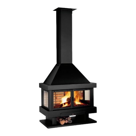
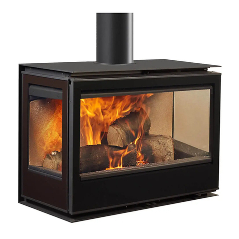
Rocal RCr User manual

ROCAL
MANUFACTURASS.A.
MANUAL DE CARACTERISTICAS, INSTALACION Y FUNCIONAMIENTO
USER’S GUIDE ON CHARACTERISTICS, ASSEMBLY AND OPERATING
MANUEL DES CARACTERISTIQUES, INSTALLATION ET FONCTIONNEMENT
MANUAL CARACTERÍSTICAS E INSTALAÇÃO E OPERAÇÃO
MANUALE DI INSTALLAZIONE E FUNZIONAMENTO CON SPECIFICHE TECNICHE
MANUFACTURAS ROCAL SA
Raval Sant Antoni, Nº 2
(08540)Centelles
Barcelona (Spain)
N.I.F.: A 58618380
INSERT
RCr –RCr GRAFFITI

Pag. 1
ESPAÑOL
ATENCIÓN:
ES MUY IMPORTANTE QUE ANTES DE PROCEDER A LA INSTALACIÓN Y PUESTA EN
MARCHA DEL APARATO LEA Y SIGA LAS INSTRUCCIONES DE ESTE MANUAL.
A: DETALLE DE LOS COMPONENTES KIT ENTREGA
1.
Bote aerosol de pintura anticalórica para retoques
2.
Herramienta para la manipulación de los registros primario y secundario y apertura de la puerta
3.
Gamuza para limpieza de la chapa
4.
Manopla antitérmica
5.
Sobre con el manual de características,instalación y funcionamiento y garantía
6.
Bolsa con los tornillos y arandelas para la sujeción de los aros de salida de aire
7.
Aros de conexión salida de aire
B: CROQUIS I MEDIDAS
Parámetro
Modelo en (mm)
RCr 50 V
RCr 65
RCr 70
RCr 70 A
RCr 80
RCr 100
RCr 70
CONICO
A –Ancho total
550
670
725
725
819
1019
692
B –Alto total
702
500
512
565
587
612
511
C –Ancho
509
629
684
684
778
978
488
D –Alto
680
478
490
543
565
590
489
E- Fondo
425
425
460
460
476
476
471
F –Fondo total
435
435
470
470
486
486
481
G- Distancia a centro salida humos
145
145
165
165
170
170
193
H –Ø Salida de humos
150
150
150
150
175-180
200
150
C: ESQUEMAS DE INSTALACION
1.
Esquemade instalación SIN CONEXIÓN TUBOSSALIDAS DE AIRE
2.
Esquemade instalación CON CONEXIÓN TUBOS SALIDA DE AIRE
D: ESQUEMAS DE MONTAGE
E: ESQUEMAS DESMONTAGE SISTEMA ELECTRICO
F: ESQUEMAS CAMBIO SENTIDO APERTURADE LA PUERTA
G: DESPIECE RECAMBIOS
1.
Cristal vitrocerámico
1- A
Cristal vitrocerámicoserigrafiado ** Solo en los modelos GRAFFITI **
2.
Piezas de vermiculita de la placa deflectora
3.
Soporte metálico de las piezas de la placa deflectora
4.
Piezas de vermiculita de fondo
5.
Piezas de vermiculita laterales
6.
Piezas metálicas de protecciónlateral ** Solo en los modelos de 80 y 100 **
7.
Reja brasas
8.
Turbinas helicoidales
9.
Bandeja para las cenizas
10.
Pieza metálicade protección frontal
H: ELEMENTOS OPCIONALES
1 - 2
Pie opcional (ajustable s/mediday extensible en altura)
3
Adaptador para marcoa 4 caras
4
Vista del insert con marcoa 4 caras
5 - 6
Marco 4 caras con 8 cm de ancho

Pag. 2
I: CARACTERÍSTICAS TÉCNICAS
Parámetro
Modelo
RCr 50 V
RCr 65
RCr 70
RCr 70 A
RCr 80
RCr 100
RCr 70
CONICO
Tiro mínimo –máximo
11-13 Pa
Consumode combustible
1,9 kg/h
1.9 kg /h
2,2 kg /h
2,2 kg /h
2,4 kg /h
3,2 kg /h
1,9 kg /h
Caudal másicode los humos
4,8 g/s
6,7 g/s
6 g/s
6 g/s
11,5 g/s
8 g/s
8 g/s
Rendimiento
80%
77%
80%
80%
81%
80%
77%
Potencia calorífica
cedida al ambiente
7 kW
6,5 kW
7,5 kW
7,5 kW
9,1 kW
10,5 kW
6,5 kW
Potencia máxima
11 kW
12 kW
15 kW
15 kW
16 kW
18 kW
12 kW
Concentración de CO medio
al 13% de O2
0,10%
0,26%
0,12%
0,12%
0,13%
0,26%
0,26%
Concentración de partículas
15mg/Nm3
(*)
17mg/Nm3
(*)
16mg/Nm3
16mg/Nm3
19mg/Nm3
20mg/Nm3
17mg/Nm3
(*)
Masa de carga (ensayo)
1,5 kg
1,4 kg
1,8 kg
1,8 kg
2,4 kg
2,3 kg
1,9 kg
Intervalo de recarga (ensayo)
47 min.
45 min.
49 min.
49 min.
45 min.
43 min.
45 min.
Tiro medio (ensayo)
12 Pa
12 Pa
12,5 Pa
12,5 Pa
13,3 Pa
12,5 Pa
12 Pa
Peso neto
93 kg
79,5 kg
95 kg
99 kg
119 kg
148 kg
88 kg
Carga Máxima Autorizada
3 kg
3 kg
4 kg
4 kg
4 kg
5 kg
4 kg
Altura recarga
200 mm
175 mm
175 mm
175 mm
175 mm
175 mm
175 mm
Longitud leños
300 mm
400 mm
450 mm
450 mm
500 mm
600 mm
400 mm
Altura mínima del conducto
4000 mm
Ø Conductosalida humos
150 mm
150 mm
150 mm
150 mm
180 mm
200 mm
150 mm
Ø Conductos salida aire
120 mm
Distanciainterior nicho hogar
(Trasera)
50 mm
Distanciainterior nicho hogar
(Laterales)
50 mm
Distanciaexterior nicho hogar
(Trasera)
200 mm
150 mm
200 mm
200 mm
200 mm
200 mm
200 mm
Distanciaexterior nicho hogar
(Laterales)
200 mm
250 mm
200 mm
200 mm
200 mm
150 mm
200 mm
Distanciaexterior nicho hogar
(Frontal)
1000 mm
Ventilación en nicho de hogar
(entrada-salida)
450 cm2
Ø Salida cable sistemaeléctrico
8 mm
Flujo aire turbinas (unidad)
135 m3/h
Potencia turbinas (unidad)
20 w
Registro primario
0% abierto
0% abierto
0% abierto
0% abierto
0% abierto
25% abierto
0% abierto
Registro secundario
40% abierto
20% abierto
50% abierto
50% abierto
50% abierto
100%abierto
50%abierto
Distanciaseguridad mín. a las
salidas de aire
250 mm
Temperatura media de humos
292º C
261º C
281º C
281º C
189º C
273º C
290º C
Tipo de combustión
INTERMITENTE
Conducto
NO COMPARTIDO
Combustible
LEÑA NATURAL
Humedad leños combustible
12-20 % - 2 AÑOS BAJO CUBIERTO
Año Certificación
2011
2013
2013
2013
Nº de Certificado
CEE/039/
13
11-2312-
895-S
CEE/039/
13
CEE/039/
13
16/12165-
714
CEE/040/
13
CEE/040/
13
(*) Valores obtenidos de ensayo laboratorio Rocal

Pag. 3
TODAS LAS REGLAMENTACIONES LOCALES, INCLUIDAS LAS QUE HAGAN REFERENCIA A
NORMAS NACIONALES O EUROPEAS HAN DE CUMPLIRSE CUANDO SE INSTALA EL
APARATO.
1.1. Hogar monobloque. Hogar con placas de vermiculita en el fondo, laterales y placa deflectora.
Parrilla brasas, bandeja cenizas y conjunto ventilación eléctrico incorporado.
El aparato viene listo para instalar.
Es necesario prever desde el interior de la boca, una salida para el cable eléctrico.
Puede desmontarse todo el interior si se desea, para hacer más fácil su transporte y colocación.
1.2. Suelo. El aparato debe instalarse en suelos que tengan una correcta capacidad portante. Si la
resistencia no es adecuada, deberá realizarse una placa de reparto para una equitativa distribución
del peso del aparato.
1.3. Salida de humos. Es obligatorio un conector de humos desde el cuello de salida del aparato
hasta la chimenea de salida de humos.
El buen estado e idoneidad de esta salida deberá estar certificada por un profesional.
También se puede prolongar este conector de humos hasta el exterior respetando en todos los casos
el diámetro de salida del aparato. Debe realizarse según la Norma al respecto. Este conducto no debe
ser compartido con otros aparatos (Véase tabla I: Características técnicas).
1.4. Aislamiento.
1.4.1. Aislamiento del aparato. Es aconsejable revestir el aparato con placas aislantes (clase
A 1, EN13501-1) en sus laterales, parte trasera y parte superior.
1.4.2. Aislamiento del nicho de hogar. Es conveniente revestir con placas aislantes (Clase A-1,
EN13501-1) las paredes interiores del nicho de hogar.
1.5. Distancias de seguridad.
1.5.1. Distancias interiores del nicho de hogar. Deben respetarse los valores que se describen en
la tabla de Características técnicas.
1.5.2. Distancias exteriores del nicho de hogar. Cualquier elemento frágil o inflamable (textiles,
electrónicos, madera, papel pintado, cristal, papel enyesado, etc.) debe separarse del nicho de hogar
respetando las distancias que se describenen la tabla I: Características técnicas.
Hay que tener especial atención en aquellas chimeneas con repisas de madera o similares: hay que
prevenir y evitar la posibilidad de que el aire caliente que expulsa el aparato incida directamente en la
madera, en ese caso se deberá aislar debidamente.
1.6. Ventilación
1.6.1. Ventilación del nicho de hogar. Se debe prever la colocación de difusores de ventilación en el
nicho de hogar tanto para la entrada como para la salida. Vease la seccion mínima que se recomienda
en la tabla I: Características técnicas.
1.6.2. Opciones para la salida del aire forzado:
- SIN conexión tubos salidas de aire (C-1). Se realiza solo la conexión de salida de humos.
NO se utilizan las salidas de aire superiores. El aire de la recámara del aparato solo sale por la
parte frontal del mismo.
- CON conexión tubos salidas de aire (C-2). Si se desea se puede conducir el aire de la
recámara del aparato a la parte superior del recinto de chimenea o a una habitación contigua;
para ello levante las tapas (D-1),atornille los collarines, y conecte la tubería (esta puede ser de
tubo rígido galvanizado o flexible de aluminio) (D-2).
Este aire de la recámara se reparte entre las salidas superiores y la parte frontal del aparato (puerta).
También se puede dirigir el aire de la recámara solo hacia las salidas de aire superiores, para ello, y
con la ayuda de la herramienta que se suministra, tire de la palanca que hay situada en la parte lateral
de la puerta (D-3, D-4).
- Con la palanca hacia abajo se cierra el paso del aire a través del frontal de la puerta y solo sale
por las salidas de aire superiores.
- Con la palanca hacia arriba, el aire sale por arriba a través de las salidas de aire superiores y
por la parte frontal de la puerta.
1. INSTRUCCIONESDE INSTALACIÓN

Pag. 4
Esta operación puede realizarse las veces que se desee.
Referente a los difusores de salida de aire, no debe haber materiales frágiles o inflamables a su
alrededor (véase lasdistancias de seguridad en la tabla I: Características técnicas).
1.6.3. Ventilación de la sala. Se debe tener en cuenta una entrada suficiente de aire exterior a la
habitación donde ubicaremos el aparato, de tal manera que no pueda bloquearse, así como el
funcionamiento simultáneo con otros aparatos de ventilación y/o calefacción tales como extractores de
aire (cocina, baño, etc.), bomba de calor, etc.; en estos casos debe compensarse la extracción con la
correspondiente entrada de aire exterior.
1.7. Nicho de hogar El nicho de hogar debe construirse con materiales incombustibles y no debe
descansar encima del aparato ni en los puntos de contacto (como por ejemplo el marco frontal).
En su interior no debe contener materiales inflamables ni frágiles tales como madera, papel pintado,
cristal, papel enyesado, etc.).
1.8. Ajustes del aparato. Es posible que en el momento de la instalación el aparato deba ajustarse.
En el supuesto que sea necesario sigalos pasos siguientes:
1.8.1. Graduar mecanismo cierre puerta (D-5). Para graduar este mecanismo ajuste el tornillo del
casquillo del mecanismo de cierre de la puerta, es la pieza situada en el módulo.
1.8.2. Graduar mecanismo bisagras (D-6). Las bisagras de la puerta también se pueden graduar y
con ello ajustar más o menos el cierre de la puerta, para ello atornille o destornille el tornillo de la
bisagra.
1.8.5. Graduar marco (D-7, D-8). Para graduar el marco destornille los 4 tornillos situados en el
marco, ajuste el marco a la medida deseaday atornille de nuevo.
1.9. Interior del aparato (D-9).
El interior del aparato está revestido con placas de vermiculita. Estas piezas vienen colocadas de
fábrica, pero se pueden desmontar para facilitar el transporte y colocación del insert o para posibles
recambios. Para ello siga los pasos siguientes:
1.9.1. Pieza lateral (D-10). Quite las piezas de vermiculita laterales.
1.9.2. Placa deflectora (D-11). Las piezas de la placa deflectora están encajadas entre si (D-12) y
sujetas por un soporte metálico. Tire de este conjunto hacia fuera, procurando que las piezas de
vermiculita no se caigan.
Atención: cuando vuelva a colocar la placa deflectora en el interior debe procurar que las
piezas encajen correctamente a las muescas y hendiduras (D-13).
1.9.3. Placas de fondo (D-14). Quite una por una las piezas de vermiculita del fondo.
ATENCIÓN:
Es importante procurar que estas piezas de vermiculita NO RECIBAN
GOLPES.
1.10. Acceso para limpieza y seguridad. Es aconsejable dejar en el nicho del hogar un acceso para
la limpieza del aparato, el conector de humos y el conducto de la chimenea.
TODAS LAS REGLAMENTACIONES LOCALES, INCLUIDAS LAS QUE HACEN REFERENCIA A
NORMAS NACIONALES O EUROPEAS HAN DE CUMPLIRSE CUANDO SE INSTALA EL APARATO
Y PARA LOS COMBUSTIBLES UTILIZADOS.
Atención: no manipule ni toque ninguna parte del aparato cuando esté en marcha sin la
protección de la manopla antitérmica.
2.1. Primeros encendidos. Para los primeros encendidos, y durante un tiempo prudencial, deben
respetarse los datos sobre la carga máxima que se describen en la tabla de Características técnicas.
2. INSTRUCCIONESDE FUNCIONAMIENTOPARA EL USUARIO

Pag. 5
ATENCIÓN:
Debe respetarse la carga máxima autorizada por el fabricante, la medida de los
leños así como la altura de la recarga.
2.2. Control de la combustión. Para obtener el rendimiento y potencia de la tabla de valores,
ajústese en la siguiente posición indicada en la tabla de Características técnicas.
2.2.1. Registro Primario (D-15). Está ubicado debajo de la bandeja de cenizas. Sirve básicamente
para el encendido que controlaremos deslizando el tirador hacia derecha o izquierda para abrir más o
menos el registro.
2.2.2. Registro secundario (D-16). Está ubicado sobre la puerta de carga frontal y sirve para ajustar
la intensidad de la combustión. Deslice el mecanismo hacia la derecha o izquierda para abrir o cerrar
el registro.
Hay que tener en cuenta que cuanto más cerrado esté el registro más suciedad se incrustará en el
cristal.
ATENCIÓN:
Las posiciones indicadas son de acuerdo a la tabla I: Características técnicas,
en todo caso, estas posiciones deben adecuarse según la depresión del
conducto y calidad del combustible.
2.3. Distancias de seguridad. Los enseres, muebles y demás elementos inflamables o frágiles
(textiles, aparatos electrónicos, madera, papel pintado, cristal, papel enyesado, etc.) no deben
acercarse a ningún punto del aparato que quede visto, así como tener en cuenta que en las salidas de
aire caliente no puede haber objetos o elementos inflamables sin que se respeten las distancias de
seguridad que se describen en la tabla de Características Técnicas.
2.4. Tipo de combustión. Este aparato es de combustión intermitente. La cámara de combustión
debe permanecer cerrada excepto en el momento de la recarga, para evitar cualquier escape de
humos, brasas y salpicaduras de combustible.
2.5. Combustibles autorizados. El aparato no debe utilizarse como incinerador y están prohibidos
otros combustibles que los autorizados por el fabricante. Como combustible solo se autoriza el uso de
leños de madera naturales no es recomendable el uso de maderas resinosas.
Están prohibidos el resto de combustibles, incluidos líquidos (en ocasiones utilizados para encender el
fuego). La longitud máxima de los leños no debe superar la longitud indicada en los datos técnicos
según modelo (véase la tabla I: Características técnicas).
2.6. Carga y recarga de combustible. Debe tenerse en cuenta la Carga Máxima Autorizada de
combustible, la longitud de los leños y la altura de la recarga cuidando que no exceda ni en cantidad ni
en tamaño a los datos especificadosanteriormente (véase la tabla I: Características técnicas).
NOTAIMPORTANTE:
Las piezas de vermiculita interiores NO DEBENRECIBIR GOLPES
cuandoseefectúala recargadecombustible.
Si algunade estaspiezasseagrieta,peroestádebidamente
colocada en su sitio, NO ALTERA EL FUNCIONAMIENTO CORRECTO DEL
MÓDULO NI COMPORTA RIESGO ALGUNO. El aparato puede utilizarse con total
normalidad.
Estas grietas no suponen ningún defecto de fabricación por lo que no entran en
garantía.
Para encender el fuego utilice materiales adecuados para ello tales como pastillas de fuego, gel para
fuego, papel y ramas secas y finas. NO UTILICE GASOLINAS, DISOLVENTES O ALCOHOL.
Coloque la carga en la zona central de la base de la cámara de combustión y a continuación prenda
lumbre. Una vez este el fuego encendido, cierre el registro primario para evitar una combustión
excesiva y controle la intensidad del fuego mediante el registro secundario.
Cuando la carga de combustible se ha reducido deberá volver a recargar teniendo en cuenta los datos
especificadosanteriormente.

Pag. 6
2.7. Apertura de la puerta (D-17). Con la ayuda de la herramienta que se suministra para este efecto,
tire de la palanca hacia fuera y se abrirá la puerta, para cerrarla efectué los mismos pasos a la
inversa.
2.8. Bloqueo de mecanismos. Es necesario comprobar la ausencia de bloqueo de todos los
mecanismos después de un período prolongado de parada.
2.9. Limpieza y mantenimiento del aparato.
2.9.1. Limpieza del cristal. Para limpiar el cristal hágalo con el aparato apagado y cuidando de que el
producto limpiador no toque las partes metálicas de la puerta ni de las juntas: debido a la agresividad
de estos productos puede iniciarse un proceso de corrosión de la puerta y del hogar.
2.9.2. Vaciado de la bandeja de cenizas (D-18). Vacíe la bandeja cuando el aparato esté
completamente apagado, cuidando que las cenizas no contengan aun brasas encendidas y
puedan provocar un incendio; en todo caso puede depositarlas en un cubo metálico.
2.9.3. Limpieza del conducto de humos y de la chimenea. Es necesario que un profesional limpie
el conducto de humos y la chimenea al menos una vez por temporada. Para ello tendrá que sacar
únicamente la placa deflectora.
2.9.4. Pintura. La pintura anticalórica que reviste el interior y exterior del aparato soporta hasta 600ºC
de temperatura y desprende un ligero olor característico que desaparece con los primeros encendidos.
Es posible que en algunas zonas del interior del hogar después de un tiempo de uso, la pintura acabe
por desaparecer, debido a la corrosión por líquidos, tipos de combustibles inadecuados u otros que los
autorizados por el fabricante, etc., en ese caso será necesario repintar todas las zonas dañadas antes
de un período prolongado de parada.
(Utilice única y exclusivamente el spray “Rocal spray pint anticalórica 600ºC NEGRA).
2.10. En caso de incendio. No debemos acercar ningún elemento inflamable a menos de 1000 mm
de cualquier punto del aparato, además debemos tomar precauciones especiales por la presencia de
niños, ancianos, etc., cerca del mismo. En caso de incendio del aparato, aparte todas las personas de
su alrededor, cierre el registro al máximo y avise al Servicio de extinción de Incendios.
2.11. Funcionamiento en condiciones climatológicas adversas. Es posible que el aparato, debido
a cambios climatológicos bruscos o inesperados, funcione incorrectamente debido a bajas presiones,
reflujos de las corrientes de aire al interior del conducto de humos: cuando se observen estos
fenómenos es recomendable cerrar todos los registros de aire de la combustión y dejar apagar el
aparato.
2.12. Modificación del aparato. Cualquier modificación que se pretenda en el aparato debe estar
autorizada por escrito por Manufacturas Rocal SA. Es recomendable, además, utilizar únicamente las
piezas de repuesto originales o recomendadas por Manufacturas Rocal SA.

Pag. 7
A continuación les mostramos una tabla con las posibles anomalías, sus causas y los remedios que
debe seguir:
FALLO
CAUSA
REMEDIO
1. Revoca humo y/o
tiro insuficiente
Conducto incorrecto
Falta de aire de alimentación para la
combustión
Revisión del conducto:
-conexión
-diámetro
-fugas en su trayecto
-longitud insuficiente
-salida al exterior
-posibles elementos que obstruyan la salida
-Revisar conductos de entrada
Funcionamiento simultaneo con otros aparatos de
ventilación y/o calefacción
2. Cristal
excesivamente sucio
Conducto incorrecto
Combustible inadecuado
Placa deflectora superior mal colocada
Revisión del conducto
Utilizar el combustible autorizado
Ajustar según instrucciones
3. Blanqueamiento del
cristal o deterioro del
color de la chapa
Exceso de temperatura causado por un
fuego excesivo en la cámara de
combustión
Revise la carga de combustible evitando el exceso de
temperatura
Ajuste los registros según el apartado 2.2.
4. Calienta poco
Combustible inadecuado
Entrada de aire, al recinto del aparato,
incorrecta
Utilizar el combustible autorizado
Revisión del recinto y, en su caso, sellado de esta
posible entrada incontrolada
5. Salida de humos y/o
gases por el frontal
Primeros encendidos
Elementos combustibles o inflamables en
el recinto o paredes circundantes al
aparato
Grieta en la cámara de combustión del
aparato
Placa deflectora superior mal colocada
Esperar que el proceso de polimerización de la
pintura finalice, esto puede tardar de uno a varios
encendidos
Revisión de materiales aislantes tales como fibra de
vidrio, maderas ignífugas o posibles elementos
combustibles y substituirlos.
Comprobar su estanqueidad y si se descubre una
grieta avisar al distribuidor o profesional.
Ajustar según instrucciones
6. Grieta en algunas de
las piezas de
vermiculita
Golpe brusco a alguna de las piezas de
vermiculita (en el momento de la recarga)
Procure efectuar la recarga de combustible sin tirar
los leños, sino colocándolos.
Haga la recarga cuando la temperatura de la cámara
de combustión haya disminuido
ATENCIÓN: Si la pieza de vermiculita solo está
agrietada pero no se mueve de su sitio, puede
continuar utilizando el aparato con absoluta
normalidad (véase apartado 2.6. Carga y recarga de
combustible)
3. DETECCIÓNDE ANOMALÍAS EN EL FUNCIONAMIENTO

Pag. 8
TODAS LAS REGLAMENTACIONES LOCALES, INCLUIDAS LAS QUE HAGAN REFERENCIA A
NORMAS NACIONALES O EUROPEAS HAN DE CUMPLIRSE CUANDO SE CONECTA EL
APARATO A LA RED ELÉCTRICA.
4.1. Componentes. Elaparato viene equipado con dos turbinas helicoidales para los modelos RCr
50 V, RCr 50 V –GARFFITI, RCr 65, RCr 70, RCr 70 GRAFFITI, RCr 70 A, RCr 70 A-GRAFFITI y RCr
70 CÓNICO y con cuatro para los modelos RCr 80, RCr 80 GRAFFITI, RCr 100 y RCr 100 GRAFFITI,
termostato para la puesta en marcha de las turbinas, resistencia, interruptor de control velocidad
turbinas, cableado interior y manguera de silicona para salida exterior.
4.2.Esquema eléctrico funcionamiento con 2 turbinas
4.2.Esquema eléctrico funcionamiento con 4 turbinas
4. INSTALACIÓNELÉCTRICA

Pag. 9
4.3. Función. La función del conjunto de ventilación es impulsar el aire tomado de las rejillas inferiores
del aparato y expulsarlo, una vez calentado, por la parte frontal y/o los difusores de la parte superior.
4.4. Uso y mantenimiento. El conjunto de ventilación debe estar permanentemente conectado a la
red eléctrica cuando el aparato está encendido.
El interruptor ofrece tres posibilidades (D-19):
-Posición o: Velocidad lenta. El arranque y paro de las turbinas es automático mediante el
termostato.
-PosiciónI: Velocidad lenta. Manualmente (sistema manual sin paro automático)
-PosiciónII: Velocidadrápida. Manualmente (sistema manual y sin paro automático).
Después de un periodo de parada prolongada y antes de poner el aparato en marcha, es necesario
comprobar el buen funcionamiento de las turbinas y limpiar toda la suciedad de las rejillas frontales de
la toma de aire. (Es conveniente, además, que un profesional cualificado revise toda la instalación
eléctrica del aparato).
ATENCIÓN:
Si el cable de alimentación está dañado debe ser sustituido por el fabricante (devolución del
aparato a fábrica), el servicio postventa o personal cualificado similar con el fin de evitar un
peligro.
El conjunto eléctrico esta instalado al insert, pero, para posibles recambios, se puede desmontar.
Para ello sigalos pasos siguientes:
5.1. DESCONETAR EL APARATO DE LA RED ELÉCTRICA.
5.2. Localización de las turbinas (E-1). En ambos lados de la bandeja de cenizas encontrará las
rejillas, justo detrás de estas rejillas, están ubicadas las turbinas. Para acceder a ellas, debe retirar
primero el protector de las turbinas destornillando los tornillos que lo sujetan. Seguidamente destornille
los tornillos que sujetan las turbinas y luego puede sacarlas inclinándolas primero y luego tirando de
ellas hacia fuera (E-2).
5.3. Componentes del sistema eléctrico. Cuando haya quitado las turbinas podrá acceder al interior
y desde allí localizar los distintos componentes del sistema eléctrico como el termostato (D-3) (que se
encuentra en el lado derecho por debajo de la reja de fuego, éste está sujeto por unas pestañas, para
sacarlo debe liberarlo de estas pestañas), la resistencia, los cables eléctricos o el interruptor.
De fábrica la toma de corriente sale por el lateral derecho, pero, si lo desea, puede salir por el lado
contrario sacando el cable de alimentación eléctrica por la apertura dellado izquierdo.
Este insert tiene la posibilidadde modificar el sentido de apertura de la puerta (la apertura standard de
fábrica es de derecha a izquierda), para ello siga los pasos siguientes:
6.1. Quitar la puerta (F-1, F-2). Para quitar la puerta, primero debe abrirla y levantarla ligeramente
hasta que haga tope arriba, tire de ella hacia fuera para liberarla del soporte inferior y luego déjela
caer hasta que quede liberada del soporte superior.
6.2. Quitar maneta y tope (F-3). Destornille los tornillos que sujetan la maneta y el tope de la maneta
de la puerta.
6.3. Fijación lateral soporte del cristal (F-4). Destornille el tornillo que sujeta la fijación lateral del
soporte del cristal.
5 . DESMONTAJE DELCONJUNTOELÉCTRICO
6 . CAMBIOSENTIDOAPERTURADE LA PUERTA

Pag. 10
6.4. Fijación superior soporte del cristal (F-5, F-6 para el modelo Graffiti). Destornille los tronillos que
sujetan la fijación superior delsoporte del cristal.
6.5. Soporte cristal (F-7, F-8 para el modelo Graffiti). Quite el soporte del cristal.
6.6. Cristal (F-9, F-10 para el modelo Graffiti). Quitar, con precaución, el cristal.
6.7. Soporte maneta (F-11). Quitar el soporte de la maneta.
6.8. Soporte lateral del marco del cristal (F-12). Quitar la pieza del soporte del marco del cristal de
la puerta.
6.9. Bisagra puerta. Finalmente debe quitar las piezas del mecanismo de las bisagras de la puerta.
Una vez desmontada toda la puerta, para modificar la apertura de la puerta, deberá colocar de nuevo
las piezas siguiendo estos pasos en sentido inverso y en el lado contrario al que estaban.
La etiqueta CE de Marcado está situada en la parte interior de la puerta de carga.
Ésta etiqueta contiene los datos técnicos, así como el Nº de O.F. (este número también lo encontrará
en la hoja de garantía).
Este número ES IMPRESCINDIBLE PARA PODER SOLICITAR PIEZAS DE RECAMBIO.
7 . MARCADO
ATENCIÓN:
- Todas las pruebas han sido realizadas siguiendo la Normativa
UNE-EN 13229:2002 - UNE-EN 13229:2002/A2:2005 - UNE-EN 13229:2002/AC:2006 –
UNE-EN 13229:2002/A2:2005/AC:2007 - UNE-EN 60335
- La revisión del aparato así como la instalación y los conductos, debe realizarla un
profesional.
- Para cualquier duda sobre lo aquí descrito, consulte con su distribuidor Rocal.
- EL INCUMPLIMINTO DELAS OBLIGACIONES AQUÍ DESCRITAS O UNA
MANIPULACION INDEBIDA DEL APARATO EXIME AL FABRICANTE DE
CUALQUIER RESPONSABILIDAD.

Pag. 11
ENGLISH
WARNING:
IT’S VERY IMPORTANT THAT BEFORE BEGINNING THE INSTALLATION AND STARTUP OF
THE APPLIANCE READ AND FOLLOW THESE INSTRUCTIONS.
A: DETAILED COMPONENTS
1.
Pot with aerosol painting for final finish
2.
Tool to manage the air slider (primary and secondary) and door
3.
Anti-scratching cloth for cleaning the plate
4.
Exothermic glove
5.
Envelope containing user’s guide: characteristics,assembly,operating and guarantee
6.
Bag with screws and washers to connectair outlet adapters
7.
Air outlet adapters
B: DIAGRAMS AND MEASURES
Model
Parameter
RCr 50 V
RCr 65
RCr 70
RCr 70 A
RCr 80
RCr 100
RCr 70
CONICO
A –Total width
550 mm
670 mm
725 mm
725 mm
819 mm
1019 mm
692 mm
B –Total high
702 mm
500 mm
512 mm
565 mm
587 mm
612 mm
511 mm
C –Width
509 mm
629 mm
684 mm
684 mm
778 mm
978 mm
488 mm
D –High
680 mm
478 mm
490 mm
543 mm
565 mm
590 mm
489 mm
E- Depth
425 mm
425 mm
460 mm
460 mm
476 mm
476 mm
471 mm
F –Total Depth
435 mm
435 mm
470 mm
470 mm
486 mm
486 mm
481 mm
G- Distance to out smoke
center
145 mm
145 mm
165 mm
165 mm
170 mm
170 mm
193 mm
H –Ø Out smoke
150 mm
150 mm
150 mm
150 mm
175-180 mm
200 mm
150 mm
C: CONNECTION PICTURES
1.
Assembly pictures WITHOUT AIR AOUTLET CONNECTION
2.
Assembly pictures WITH AIR OUTLET CONNECTION
D: ASSEMBLY PICTURES
E: DISMANTLING FORCED AIR VENTILATION SYSTEM PICTURES
F: SCHEMES FOR CHANGE DIRECTION OF OPENING THE DOOR
G: SPARE PARTS PICTURE
1.
Vitroceramic glass
1- A
Vitroceramic decorared glass ** Only models GRAFFITI **
2.
Vermiculite deflected panel pieces
3.
Vermiculite deflected panel pieces metallic support
4.
Vermiculite back pieces
5.
Vermiculite side pieces
6.
Side metallic fire protection pieces ** Only for models 80 y 100 **
7.
Fire grate
8.
Fun of 135 m3/h
9.
Ash pan
10.
Frontal metallic fire protection piece
H:OPTIONAL COMPLEMENTS
1 - 2
Optional foot (according adjustable, adjustable height measures)
3
Adapter to 4 sides frame
4
4 sides frame scheme
5 - 6
4 sides of 8 cm frame scheme

Pag. 12
I: TECHNICAL CHARACTERISTICS
Model
Parameter
RCr 50 V
RCr 65
RCr 70
RCr 70 A
RCr 80
RCr 100
RCr 70
CONICO
Maximum smokestackintake
11-13 Pa
Fuel consumption
1,9 Kg/h
1,9 Kg/h
2,2 Kg/h
2,2 Kg/h
2,4 Kg/h
3,2 Kg/h
1,9 Kg/h
Mass smokeintake
4,8 g/s
6,7 g/s
6 g/s
6 g/s
11,5 g/s
8 g/s
8 g/s
Nominal efficiency
80%
77%
80%
80%
81%
80%
77%
Output
7 Kw
6,5 Kw
7,5 Kw
7,5 Kw
9,1 Kw
10,5 Kw
6,5 Kw
Maximum output
11 Kw
12 Kw
15 Kw
15 Kw
16 Kw
18 Kw
12 Kw
CO concentration at an average of
13% O2
0,10%
0,26%
0,12%
0,12%
0,13%
0,26%
0,26%
Particle concentration
15mg/Nm3
(*)
17mg/Nm3
(*)
16mg/Nm3
16mg/Nm3
19mg/Nm3
20mg/Nm3
17mg/Nm3
(*)
Fuel load (test)
1,5 Kg
1,4 Kg
1,8 Kg
1,8 Kg
2,4 Kg
2,3 Kg
1,9 Kg
Period time to test
47 min.
45 min.
49 min.
49 min.
45 min.
43 min.
45 min.
Average smokestackintak (test)
12 Pa
12 Pa
12,5 Pa
12,5 Pa
13,3 Pa
12,5 Pa
12 Pa
Net Weight
93 Kg
79,5 Kg
95 Kg
99 Kg
119 Kg
148 Kg
88 Kg
Maximum fuel load
3 Kg
3 Kg
4 Kg
4 Kg
4 Kg
5 Kg
4 Kg
High recharge
200 mm
175 mm
175 mm
175 mm
175 mm
175 mm
175 mm
Length woodlogs
300 mm
400 mm
450 mm
450 mm
500 mm
600 mm
400 mm
Minimum height of pipe
4000 mm
Ø Flue duct
150 mm
150 mm
150 mm
150 mm
180 mm
200 mm
150 mm
Ø Air outlet ducs
120 mm
Inner fireplace room safety
distances (back)
50 mm
Inner fireplace safety distances
(sides)
50 mm
Outer fireplace safety distances
(back)
200 mm
150 mm
200 mm
200 mm
200 mm
200 mm
200 mm
Outer fireplace safety distances
(sides)
200 mm
250 mm
200 mm
200 mm
200 mm
150 mm
200 mm
Outer fireplace safety distances
(frontal)
1000 mm
Fireplace room ventilation
(entry - exit)
450 cm2
Ø Electric cable exit
8 mm
Fun airflow (unit)
135 m3/h
Fun output (unit)
20 w
Primary register
0% open
0% open
0% open
0% open
0% open
25% open
0% open
Secondary register
40%
open
20%
open
50%
open
50%
open
50%
open
100%
open
50%
open
Minimum safety distance to the air
outlets
250 mm
Temperature of fumes
292º C
261º C
281º C
281º C
189º C
273º C
290º C
Fire type
ON AND OFF
Pipe
NOT SHARE
Fuel
NATURAL WOOD
Logs humidity
12-20 % - 2 UNDER COVER
Cetification year
2011
2013
2013
2013
Nº Certificate
CEE/039/
13
11-2312-
895-S
CEE/039/
13
CEE/039/
13
16/12165-
714
CEE/040/
13
CEE/040/
13
(*) Values obtained from Rocal laboratory test

Pag. 13
ALL LOCAL REGULATIONS, INCLUDING THE ONES ACCORDING TO THE NATIONAL
OREUROPEAN NORMS MUST BE ACCOMPLISHED WHEN PROCEEDING TO INSTALL THE
FIREPLACE.
1.1. Mono-block fire. “Vermiculite” home plate at the bottom, sides and baffle plate, fire
grate, ash pan and ventilation set incorporated.
The fireplace comes ready to install.
Provision should be made from inside an output for the electric cable.
All the inner can be removed if desired, for easier transportation and installation.
1.2. Floor. This fireplace must be assembled on floors, which provide an adequate bearing capacity.
If the resistance is not enough, a panel of balance would be required to distribute the whole weight of
the fireplace.
1.3. Smokestack. A smoke connector from the adapter is needed to the smoke outlet.
This outlet must be in good conditions and certified by a professional.
It can also be possible to lengthen the pipe to the outdoors providing, in any case, the exact diameter
for the fireplace.
The installation procedures must be done under the regulations.
It is not possible to use this pipefor any other purpose. This smokestack must be shared with other
devices (You can see I: Technical characteristics).
1.4. Insulating procedures.
1.4.1. Apparatus insulation. The fireplace must be insulated with insulation panels (Type A-
1,EN13501-1) on its sides, back and upper part.
1.4.2 Fireplace room insulation. It is also convenient to use insulation panels on the inner walls of the
fireplace (Type A-1, EN13501-1).
1.5. Safety distances.
1.5.1. Inner fireplace room safety distances. You must be respected the values described in
I:Technical characteristics.
1.5.2. Outer fireplace safety distances. Anything fragile or flammable (textile, electronics, wood,
paper wall, glass, chalk…) should be separated of the appliance and respected the safety distances
described in I: Technical characteristics.
We must take special care in those fireplaces with wooden shelves or similar: we must prevent and
avoid the possibility of hot air that expels the device falls directly on the wood, in these cases,
flammable items should be properly insulated.
1.6. Ventilation.
1.6.1. Fireplace room ventilation. The appliance must be provided with an air outlet or inlet diffusers
for sufficient air flow as described in I: Technical characteristics
For this ventilation exist two options:
-WITHOUT air outlet pipes connection (C-1). Only done the flue connection. NO used the upper
air outlet, the fireplace room air is output from the front of it. You must done an input and output in
fireplace room of the appliance.
-WITH air outlet pipes connection (C-2). If you want you can drive the air from fireplace room to
the top or adjoining room, by lifting the lids (D-1), screw collars, and connect the pipe (this can be
Flexible galvanized aluminum or rigid pipe) (D-2).
This air of the chamber is shared between the upper outlets and the front of the appliance (door). You
can also direct the air from the chamber only to the upper air outlets for that, and with the help of the
tool provided, pull the lever located on the side of the door (D-3, D-4).
- With the lever down air passage closes through the front door and leaving the outputs only upper.
- With the lever up, the air comes up through the upper air outlets and the front door.
This can be done as often as desired.
Concerning the air outlet, there should be fragile or flammable materials around (see the safety
distances in Table I: Technical characteristics).
1 . INSTALLATIONPROCEDURES

Pag. 14
1.6.2. Room Ventilation. It should take into account a sufficient outside air to the room where we will
place the appliance so that it cannot be blocked, and the simultaneous operation with other ventilation
devices and / or heat such as exhaust fans (kitchen, bathroom, etc.), heat pump, etc... In these cases
must be compensated extraction with the entry of outside air.
1.7. Fireplace Room. It must be built with non-flammable material and should not be sitting on top of
the apparatus. In reference to the contact points (front frame. Neither flammable nor fragile material
can be contained inside (wood, paper wall, glass, chalk…).
1.8.Possible appliance adjustments. It is possible that the installation, the appliance is
adjusted, if so, the following steps:
1.8.1. Door closing mechanism graduate (D-5). This adjustment mechanism for adjusting screw cap
closure mechanism of the door, that is a part located on the module.
1.8.2. Graduate hinges mechanism (D-6). The door hinges can also be graduating and thus set
about closing the door to tighten or loosen this screw hinge.
1.8.3. Frame adjustment (D-7, D-8). Unscrew the 4 screws on the frame, fit the frame and tighten
again.
1.9. Inside the appliance (D-9).
Inside of the appliance is coated with vermiculite plates. These are placed direct, but can be
disassembled for easy transport and positioning of the insert or for possible replacements.
1.9.1. Side pieces (D-10). Remove the vermiculite side pieces
1.9.2. Baffle plate (D-11). The baffle plate piecesare engaged with each other and fix with a metallic
support. Pull out this set ensuring that the vermiculite pieces not fall.
Warning:
When replacing the baffle plate must ensure that the pieces fit correctly (D-13)
1.9.3. Back pieces(D-14). Remove one by one the pieces of vermiculite from the bottom.
WARNING:
It is important to ensure that these vermiculite pieces NO RECEIVINGKNOCKS.
1.10. Cleaning and maintenance. It is highly recommended an accessible zone for the cleaning of the
apparatus, smoke chamber and smokestack.
ALL LOCAL, NATIONAL AND EUROPEAN STANDARDS MUST BE COMPLIED WITH
WHENINSTALLING THE APPLIANCE AND USED FUELS.
Warning: Do not operate or handle any part when the fireplace is working unless using the
exothermic glove.
2.1. Using for the first time. For early on, and for a reasonable time, the data on the maximum load
as specified in the table of Technical characteristics must be respected.
WARNING:
You must respect the maximum load allowed by the manufacturer of the
logs as well as the height of the recharge.
2.2. Fire control. To obtain the correct performance, adjust the position show the following table I:
Technical characteristics.
2. USER’S GUIDE

Pag. 15
2.2.1. Primary slider control (D-15). Is located below the ash pan. It is used basically for lighting the
fire, will control moving the handle right or left to open more or less.
2.2.2. Secondary slider control (D-16). Is located above the loading door and is used to adjust the
combustion more or less. Slide the handle to right or left to open or close.
The closer the register, the dirtier the glass.
WARNING:
The positions indicated are according to technical characteristics table, in
any case these positions must be adapt according to the flue depression and
fuel quality.
2.3. Safety distances. Appliances, furniture and other flammable or breakable items (textiles,
electronics, wood, wallpaper, glass, chalk paper, etc..) must not approach any point of the product it is
seen, and bear in mind that the outputs hot air cannot be objects or flammable items without safety
distances described in the I: Technical characteristics.
2.4. Fire types. This apparatus is an on and off fire. The smoke chamber must be closed except when
being loaded, to avoid any smoke out fuel debris. It is convenient when loading the fireplace, to avoid
any leak or smoke escape.
2.5. Authorized fuel. The appliance should not be used as an incinerator and other fuels that are
forbidden by the manufacturer's authorized. As fuel only use natural wood logs is not advisable to
use resinous wood is allowed.
Are forbidden other fuels, including liquid (sometimes used to start the fire).
The maximum length of the logs should not exceed the length specified in the technical data according
to model (see Table I: Technical characteristics).
2.6. Loading and reload fuel. It must take into account the maximum authorised load of fuel, ensuring
that when the recharge. The fuel can’t overtake the limit, taking care not to exceed either in quantity or
size to the data specified above (youcan see the I: TechnicalCharacteristics).
WARNING- IMPORTANT NOTE:
Interiorparts vermiculite SHOULD NOT BE HIT, especiallywhen
donerefueling.
If any ofthesepartsarecracked,butis properlyplaced inyour
site, doesnotalterthe properfunctioning ofNI A POTENTIALRISK. The device
can be used normally.
Thesecracks do not poseany manufacturing defectssoyou do not fall under warranty.
To light the fire using materials suitable for this purpose, such as fire pads, gel fire, paper and dry and
thin branches. DO NOT USE GASOLINE, SOLVENTS OR ALCOHOL.
To make the procedure ignition follow these steps: placing the burden on the central area of the
database from home, open the register primary and secondary maximum and then fire pledge. Once
the fire is lit, close the primary register to prevent excessive combustion and control the intensity by the
secondary registers.
When the fuel load is reduced you will have to recharge considering data specified above.
2.7. Opening the door (D-17). With the help of the tool, pull the handle out opens the door to close
perform the same steps in reverse.
2.8. Mechanism blockage. It is compulsory to check any piece because they might get stuck after a
long period of time without using the fireplace.
2.9. Cleaning and maintenance.
2.9.1. Glass cleaning. To clean the glass, the appliance must not be operating. Do not clean with any
liquid either the metal parts of the door or the seal, in order to prevent damage.

Pag. 16
2.9.2. Ash pan cleaning (D-18). Empty the tray when the appliance is turned off completely, making
sure that the ashes do not contain even hot embers and may result in fire, in any case may deposit
them in a metal bucket.
2.9.3. Smokestack and fireplace cleaning. You need a professional to clean chimney and fireplace
at least once a year. The only thing to be done is to remove the two deflected panels.
2.9.4. Painting. The heat-resistant paint that lines the inside and outside of the appliance supports up
to 600 ° C temperature and shows a slight characteristic odor disappears early on.
It is also possible that after some time, the paint inside the fireplace wears off due to the liquid
corrosion, fuel or other reasons. In this case, it will be necessary to wear the rusty zones off and
repaint them again
(Use only and exclusively use the spray "spray pint Rocal anticalórica BLACK 600 º C).
2.10. Fire Prevention. No flammable element must be placed the nearest at 1000 mm away from the
fireplace. Special prevention must be taken when children or elderly around. In case of a fire, move
away all people around, close registers and call the Firemen Department.
2.11. Operating the fireplace under certain weather conditions. It is possible that under certain
weather conditions the apparatus doesn’t work properly: smoke mislead or not enough intake. When
observing these phenomena, it is highly recommended to close all air registers and extinguish the fire.
2.12. Fireplace modification. Any modification must be authorised by means of writing on behalf of
Manufacturas Rocal SA. It is also compulsory to use the spare piecesrecommended by Manufacturas
Rocal SA.

Pag. 17
The table below shows the possible malfunctions, what brought them about and the solutions to follow:
MALFUNCTION
CAUSE
SOLUTION
1. Smoke mislead or
insufficient air intake.
Inadequate pipe.
Insufficient air for combustion
Check pipe:
-connection
-diameter
-leaks
-insufficient length
-outlet
-blockage
Check the flue draught entry
Other ventilation or heating device work
simultaneously
2. Glass (too dirty)
Inadequate pipe.
Inadequate fuel.
Upper deflected panel misadjusted
Check pipe
Use authorized fuel
Adjust according directions
3. Whitening of the glass
or damage the color of the
plate
Excess temperature caused by an
excessive fire in the combustion
chamber
Check the fuel load
Set the registers according to paragraph
2.2.
4. Little heating
Inadequate fuel.
Inadequate air inlet to smokestack
Authorized fuel
Check chamber and seal to the flue
5. Smoke going out
through front door.
First lit.
Flammable or combustible elements
inside the fireplace or around.
Crack in the flue.
Upper deflected panel misadjusted
Wait for the polymerisation process (more
than one lit)
Check insulation material (glass fibre,
igneous wood or other elements), possibly
replace them
Check for cracks and call dealer
Adjust according directions.
6. Cracks in some parts of
vermiculite inside
Beat in one of the pieces performed,
especially at the time of recharge
Try not to pull the logs but put
Perform charging where the temperature of
the combustion chamber has decreased
NOTE: If the part is only cracked but
does not move from your site, you can
continue using the device with absolute
normality (see section 2.6. Loading and
refueling)
3. DETECTIONOF MALFUNCTION

Pag. 18
ALL LOCAL REGULATIONS, INCLUDING THE ONES ACCORDING TO THE NATIONAL
OREUROPEAN NORMS MUST BE ACCOMPLISHED WHEN PROCEEDING TO CONNECT THEA
PPARATUS TO ELECTRICAL INSTALLATIONS
4.1. Components. The appliance is equipped with two fans for models RCr 50 V, RCr 50 GRAFFITI,
RCr 65, RCr 70, RCr 70 GRAFFITI, RCr 70 A, RCr 70 A-GRAFFITI and RCr 70 CONIQUE, a
thermostat and an ignition device, resistance, turbine control switch, inner cables and wires as well as
silicon tube for air outlet.
4.2.Electrical diagram with 2 fans.
4.2.Electrical diagram with 4 fans.
4.3. Operating. The function of the vent set is to jet the air, once heated, from the lower grill of the
apparatus to the front part and the pipesin the upper part.
4 . ELECTRICALINSTALLATION

Pag. 19
4.4. Use and maintenance. The set of ventilation should be permanently connected to the grid when
the device is switched on.
The switch offers three positions (C-25):
- Position0: Slow gear. The starting and stoppage of the turbines is through the automatic thermostat.
- PositionI: Slow gear. Manually (manual, not automatic shutdown system)
- PositionII: Fast gear. Manually (manual, not automatic shutdown system)
After a period of prolonged and stop before putting the machine in motion, it is necessary to verify the
proper operation of the turbines and cleaned all the dirt of the front grilles of the air intake. It is also
desirable that a qualified professional review the entire electrical installation of the device.
WARNING:
If the feeding wires are damaged, they must be replaced either by the manufacturers (returning
the apparatus to the factory), sales department or qualified staff to avoid problems.
The electrical assembly is installed to insert, but for possible replacements, can be removed.
To do this follow these steps:
5.1. DISCONNECT THE APPLIANCE THE ELECTRICAL NETWORK.
5.2. Fan location (E-1). On both sides of the ash tray find the grids, behind these grids you can find a
fans. To access them you must first remove the protector of fans unscrewing the screws that hold it
and then you can remove the fan tilting first and then pulling them out (E-2).
5.3. Electrical system components. When the fans removed will have access to the interior and from
there locate the electrical system components such us the thermostat (E-3) (located on the right side,
below the fire grate, is attached by some tabs to remove it must release these tabs), resistance,
electrical wiring or switch.
From manufacturing, the electrical system outlet on the right side out, but if you wish, you can change
on the opposite side by removing the electrical power cord from the left side.
This appliance has to change the direction of opening the door (standard is from right to left), to do the
following steps:
6.1. Removing the door (F-1, F-2). To remove the door, you must first open it and lift it slightly until it
stops up, pull it out to release the bottom bracket and then drop it until it is released from the top
bracket.
6.2. Remove handle and stop (F-3). Unscrew the screws holding the handle and the top of the handle
of the door.
6.3. Glass side mounting support (F-4). Unscrew the screw holding the bracket side fixing glass.
6.4. Upper fixing support the glass (F-5, F-6 for Graffiti models). Unscrew the bolts holding the upper
attachment of the support of glass.
6.5. Glass support (F-7, F-8 for Graffiti models). Remove the glass support.
6.6. Glass (F-9, F-10 for Graffiti models). Remove with caution, glass.
6.7. Support handle (F-11). Remove the handle support.
6.8. Side support frame the glass (F-12). Remove part of the support frame of the door glass.
6.9. Door hinges. Finally you must remove parts of the mechanism of the door hinges.
After removing all the door to change the door opening, you must put back the pieces following these
steps in reverse and the opposite side they were.
5. REMOVINGTHEELECTRICALSYSTEM
6. DOOROPENING CHANGE
This manual suits for next models
8
Table of contents
Languages:
Other Rocal Stove manuals
Popular Stove manuals by other brands

Nordica
Nordica FULVIA Instructions for installation, use and maintenance

Extraflame
Extraflame UPPER LOADING KIT instruction manual

Breckwell
Breckwell Cadet P26FS owner's manual

Valor
Valor ovation 810 Installation and operating guide

Dimplex
Dimplex Optiflame Cassia Noir RTOFSTV20 Operating instructions manual

Coleman
Coleman 5442-A50 Instructions for use