Rockwell international Allen-Bradley 1747-PTA1E User manual

-~
ARTISAN
®
~I
TECHNOLOGY
GROUP
Your definitive source
for
quality
pre-owned
equipment.
Artisan Technology
Group
Full-service,
independent
repair
center
with
experienced
engineers
and
technicians
on staff.
We
buy
your
excess,
underutilized,
and
idle
equipment
along
with
credit
for
buybacks
and
trade-ins
.
Custom
engineering
so
your
equipment
works
exactly as
you
specify.
•
Critical
and
expedited
services
•
Leasing
/
Rentals/
Demos
• In
stock/
Ready-to-ship
•
!TAR-certified
secure
asset
solutions
Expert
team
ITrust
guarantee
I
100%
satisfaction
All
tr
ademarks,
br
a
nd
names, a
nd
br
a
nd
s a
pp
earing here
in
are
th
e property of
th
e
ir
r
es
pecti
ve
ow
ner
s.
Find the Rockwell / Allen-Bradley 1747-PT1 at our website: Click HERE

ALLEN–BRADLEY
The Getting Started Guide for HHT
(Catalog Number 1747–PTA1E & 1747–PT1)
User Manual
Artisan Technology Group - Quality Instrumentation ... Guaranteed | (888) 88-SOURCE | www.artisantg.com

Solid state equipment has operational characteristics differing from those of
electromechanical equipment. “Safety Guidelines for the Application,
Installation and Maintenance of Solid State Controls” (Publication SGI-1.1)
describes some important differences between solid state equipment and
hard–wired electromechanical devices. Because of this difference, and also
because of the wide variety of uses for solid state equipment, all persons
responsible for applying this equipment must satisfy themselves that each
intended application of this equipment is acceptable.
In no event will the Allen-Bradley Company be responsible or liable for
indirect or consequential damages resulting from the use or application of
this equipment.
The examples and diagrams in this manual are included solely for illustrative
purposes. Because of the many variables and requirements associated with
any particular installation, the Allen-Bradley Company cannot assume
responsibility or liability for actual use based on the examples and diagrams.
No patent liability is assumed by Allen-Bradley Company with respect to use
of information, circuits, equipment, or software described in this manual.
Reproduction of the contents of this manual, in whole or in part, without
written permission of the Allen-Bradley Company is prohibited.
Throughout this manual we use notes to make you aware of safety
considerations.
!ATTENTION: Identifies information about practices or
circumstances that can lead to personal injury or death, property
damage, or economic loss.
Attentions help you:
•identify a hazard
•avoid the hazard
•recognize the consequences
Important: Identifies information that is especially important for successful
application and understanding of the product.
PLC, PLC 2, PLC 3, and PLC 5 are registered trademarks of Allen-Bradley Company, Inc.
SLC, SLC 500, PanelView, RediPANEL, and Dataliner are trademarks of Allen-Bradley Company, Inc.
IBM is a registered trademark of International Business Machines, Incorporated.
Important User Information
Artisan Technology Group - Quality Instrumentation ... Guaranteed | (888) 88-SOURCE | www.artisantg.com

Preface
P–1
Preface
Read this preface to familiarize yourself with the rest of the manual. This
preface covers the following topics:
•who should use this manual
•the purpose of this manual
•how to use this manual
•conventions used in this manual
•Allen–Bradley support
Use this manual if you are responsible for designing, installing,
programming, or troubleshooting control systems that use Allen–Bradley
small logic controllers.
You should have a basic understanding of SLC 500 products. You should
understand programmable controllers and be able to interpret the ladder logic
instructions required to control your application. If you do not, contact your
local Allen–Bradley representative for information on available training
courses before using this product.
This manual is a learning and reference guide for the HHT. It is an
introductory document, designed to allow you to begin programming in the
shortest time possible. It does this by focusing on a simple controller and a
simple program. Basic concepts are presented, but only with enough detail
to get you started and let you know that there is more to be learned.
Who Should Use this
Manual
Purpose of this Manual
Artisan Technology Group - Quality Instrumentation ... Guaranteed | (888) 88-SOURCE | www.artisantg.com

Preface
P–2
Contents of this Manual
Chapter: Title: Purpose:
1Setting Up Your Equipment Shows you how to set up a controller, install your
Memory Pak, Battery, and communication cable,
and connect your HHT to the controller.
2Control Basics Presents basic information you will need to know
before you can begin programming with the HHT.
3Creating a Program Shows you how to create a program.
4Online Operations Shows you how to download (restore) your program
to the controller, monitor, and test the program.
Appendix
AAdditional Ladder Program
Exercises Introduces you to branching of instructions and the
timer instruction.
Appendix
BTroubleshooting Errors Provides a listing of error messages that you may
encounter while working through the guide. Also,
offers possible solutions for these errors.
Appendix
CIdentifying HHT Function Keys
& Instruction Mnemonics Provides a listing of HHT function keys and their
meaning. Also provided is a list of instruction
mnemonics.
Glossary Glossary Provides definitions of terms used in this guide.
Related Documentation
The following documents contain additional information concerning
Allen–Bradley SLC and PLC products. To obtain a copy, contact your local
Allen–Bradley office or distributor.
For Read this Document Document
Number
An overview of the SLC 500 family of products SLC 500 System Overview 1747–2.30
A description on how to install and use your Modular SLC 500
programmable controller Installation & Operation Manual for Modular Hardware
Style Programmable Controllers 1747–804
A description on how to install and use your Fixed SLC 500
programmable controller Installation & Operation Manual for Fixed Hardware Style
Programmable Controllers 1747–800
A procedural and reference manual for technical personnel who use an
HHT to develop control applications Allen–Bradley Hand–Held Terminal User’s Manual 1747–809
A complete listing of current Automation Group documentation, including
ordering instructions. Also indicates whether the documents are
available on CD–ROM or in multi–languages. Automation Group Publication Index SD499
A glossary of industrial automation terms and abbreviations Allen–Bradley Industrial Automation Glossary ICCG–7.1
Artisan Technology Group - Quality Instrumentation ... Guaranteed | (888) 88-SOURCE | www.artisantg.com

Preface
P–3
To use this manual effectively:
•Work through the chapters in sequential order, completing each one
before moving on to the next.
•Perform the exercises in appendix A to apply what you have learned in
the chapters.
•Consult appendix B to correct and identify any errors you encounter while
working through this manual.
•Refer to the glossary for definitions of unfamiliar terms.
•Use the index to locate further information on topics.
The following conventions are used throughout this manual:
•Bulleted lists such as this one provide information, not procedural steps.
•Numbered lists provide sequential steps or hierarchical information.
•Italic type is used for emphasis.
•Text in this
font
indicates words or phrases you should type.
•Key names match the names shown and appear in bold, capital letters
within brackets (for example, [ENTER]).
Allen–Bradley offers support services worldwide, with 78 Sales Support
offices, 494 Authorized Distributors and 242 authorized Systems Integrators
located throughout the United States, plus Allen–Bradley representatives in
every major country in the world.
Local Product Support
Contact your local Allen–Bradley representative for:
•Sales and Order Support
•Product Technical Training
•Warranty Support
•Support Service Agreements
Technical Product Assistance
If you need to contact Allen–Bradley for technical assistance, please review
the information in appendix B, Troubleshooting Errors, first. Then call your
local Allen–Bradley representative.
Your Questions or Comments on this Manual
If you have any suggestions for how this manual could be made more useful
to you, please send us your ideas on the enclosed reply card.
If you find a problem with this manual, please notify us of it on the enclosed
Publication Problem Report.
How to Use this Manual
Common Techniques Used
in this Manual
Allen–Bradley Support
Artisan Technology Group - Quality Instrumentation ... Guaranteed | (888) 88-SOURCE | www.artisantg.com

The Getting Started Guide for HHT
T
able of Contents
i
Chapter 1
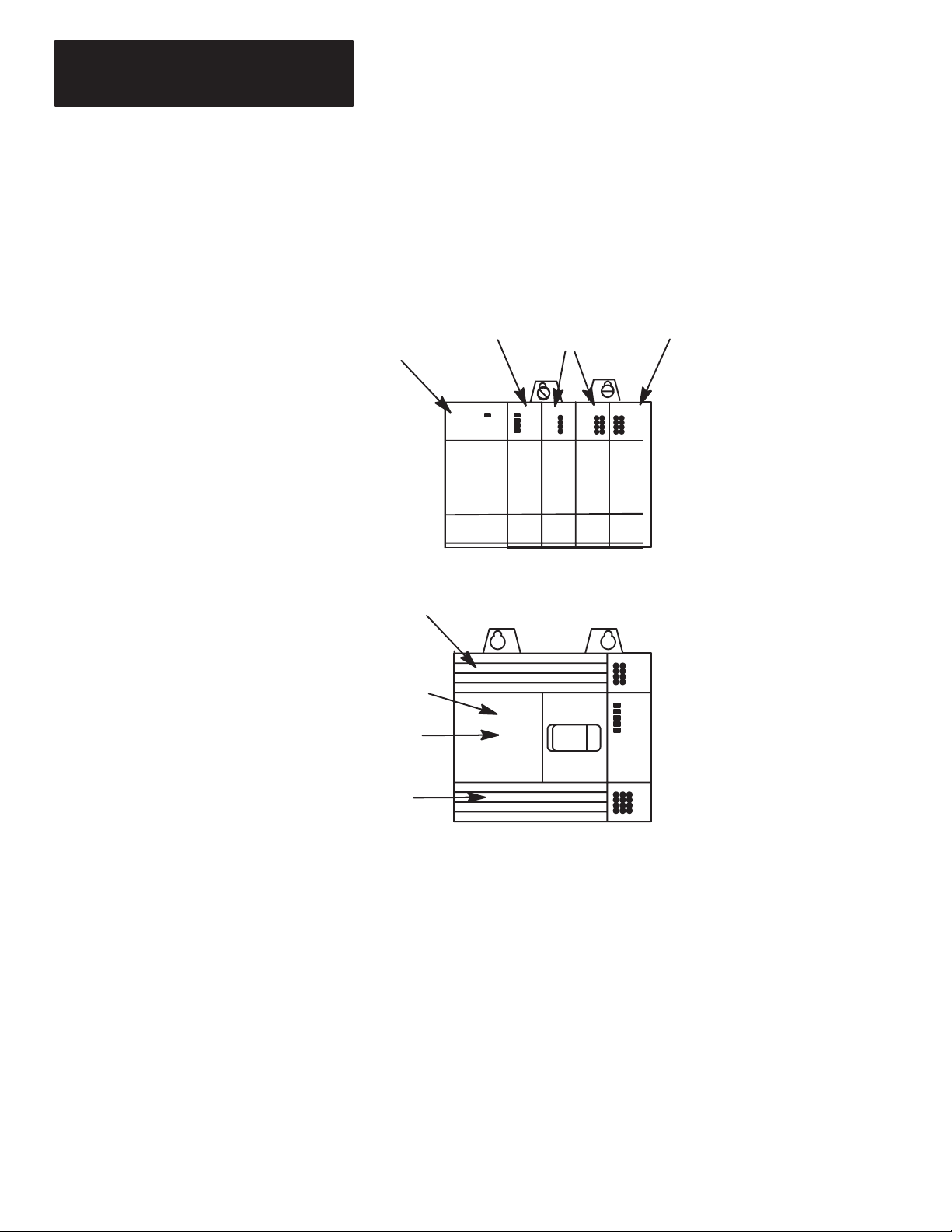
Controller Styles 1–2. . . . . . . . . . . . . . . . . . . . . . . . . . . . . . . . . . . . . . . . . . . .
Setting
Up a Demo Unit
1–3. . . . . . . . . . . . . . . . . . . . . . . . . . . . . . . . . . . . . . .
Setting
Up a Field–Wired Controller
1–4. . . . . . . . . . . . . . . . . . . . . . . . . . . . . . .
Installing the Memory Pak, Battery
, and Communication Cable
1–4. . . . . . . . . . .
HHT
Features
1–8. . . . . . . . . . . . . . . . . . . . . . . . . . . . . . . . . . . . . . . . . . . . . .
HHT
Powerup
1–9. . . . . . . . . . . . . . . . . . . . . . . . . . . . . . . . . . . . . . . . . . . . . .
HHT Display Format 1–9. . . . . . . . . . . . . . . . . . . . . . . . . . . . . . . . . . . . . . . . .
The
Keyboard
1–9. . . . . . . . . . . . . . . . . . . . . . . . . . . . . . . . . . . . . . . . . . . . . .
Menu
Function Keys (F1, F2, F3, F4, F5)
1–9. . . . . . . . . . . . . . . . . . . . . . . . .
Data Entry Keys (A 7, B 8, C 9...) 1–10. . . . . . . . . . . . . . . . . . . . . . . . . . . . . .
Auto
Shift
1–10. . . . . . . . . . . . . . . . . . . . . . . . . . . . . . . . . . . . . . . . . . . . . . .
Cursor Keys 1–10. . . . . . . . . . . . . . . . . . . . . . . . . . . . . . . . . . . . . . . . . . . . .
ZOOM and RUNG Keys 1–10. . . . . . . . . . . . . . . . . . . . . . . . . . . . . . . . . . . . .
Chapter 2
SLC
500 File Concepts
2–1. . . . . . . . . . . . . . . . . . . . . . . . . . . . . . . . . . . . . . .
Program 2–1. . . . . . . . . . . . . . . . . . . . . . . . . . . . . . . . . . . . . . . . . . . . . . . .
Program
Files
2–2. . . . . . . . . . . . . . . . . . . . . . . . . . . . . . . . . . . . . . . . . . . .
Data
Files
2–2. . . . . . . . . . . . . . . . . . . . . . . . . . . . . . . . . . . . . . . . . . . . . . .
How External I/O Devices Communicate with the Processor 2–3. . . . . . . . . . . . .
Addressing
External I/O
2–4. . . . . . . . . . . . . . . . . . . . . . . . . . . . . . . . . . . . . . .
External I/O Addressing Formats 2–5. . . . . . . . . . . . . . . . . . . . . . . . . . . . . . . .
HHT Display of Instructions/Addresses 2–5. . . . . . . . . . . . . . . . . . . . . . . . . .
Ladder
Logic Concepts
2–6. . . . . . . . . . . . . . . . . . . . . . . . . . . . . . . . . . . . . . .
True/False
Status
2–6. . . . . . . . . . . . . . . . . . . . . . . . . . . . . . . . . . . . . . . . .
Logical
Continuity
2–7. . . . . . . . . . . . . . . . . . . . . . . . . . . . . . . . . . . . . . . . .
Processor Operating Cycle 2–8. . . . . . . . . . . . . . . . . . . . . . . . . . . . . . . . . . .
Chapter 3
Configuration
of SLC 500 Controllers
3–1. . . . . . . . . . . . . . . . . . . . . . . . . . . . . .
Controller Styles 3–2. . . . . . . . . . . . . . . . . . . . . . . . . . . . . . . . . . . . . . . . . .
Catalog Numbers 3–2. . . . . . . . . . . . . . . . . . . . . . . . . . . . . . . . . . . . . . . . . .
Arbitrary
Controller Used in this Guide
3–4. . . . . . . . . . . . . . . . . . . . . . . . . . .
Creating
a Program
3–4. . . . . . . . . . . . . . . . . . . . . . . . . . . . . . . . . . . . . . . . . .
Clearing the Memory of the HHT 3–5. . . . . . . . . . . . . . . . . . . . . . . . . . . . . . .
Naming
the Program and Configuring the Controller
3–6. . . . . . . . . . . . . . . . .
Naming Your Program 3–6. . . . . . . . . . . . . . . . . . . . . . . . . . . . . . . . . . . .
Configuring the Processor 3–7. . . . . . . . . . . . . . . . . . . . . . . . . . . . . . . . .
ConfiguringY
our I/O
3–8. . . . . . . . . . . . . . . . . . . . . . . . . . . . . . . . . . . . . .
Monitoring Y
our Data File
3–10. . . . . . . . . . . . . . . . . . . . . . . . . . . . . . . . . .
Programming
a Simple Ladder Rung
3–11. . . . . . . . . . . . . . . . . . . . . . . . . . . .
Entering
a Rung
3–11. . . . . . . . . . . . . . . . . . . . . . . . . . . . . . . . . . . . . . . . .
Setting Up Your Equipment
Control Basics
Creating a Program
Artisan Technology Group - Quality Instrumentation ... Guaranteed | (888) 88-SOURCE | www.artisantg.com

The Getting Started Guide for HHT
T
able of Contents
ii
Entering
an “Examine if Closed” Instruction
3–12. . . . . . . . . . . . . . . . . . . . .
Entering
an “Output Energize” Instruction
3–13. . . . . . . . . . . . . . . . . . . . . . .
Saving Your Program 3–14. . . . . . . . . . . . . . . . . . . . . . . . . . . . . . . . . . . . . . .
Chapter 4
Downloading Your Program 4–2. . . . . . . . . . . . . . . . . . . . . . . . . . . . . . . . . . . .
Going
Online
4–2. . . . . . . . . . . . . . . . . . . . . . . . . . . . . . . . . . . . . . . . . . . . .
Downloading Your Program 4–3. . . . . . . . . . . . . . . . . . . . . . . . . . . . . . . . . .
Changing
Program Mode to Run Mode
4–3. . . . . . . . . . . . . . . . . . . . . . . . . .
Monitoring
the Program in Run Mode
4–4. . . . . . . . . . . . . . . . . . . . . . . . . . .
Testing Y
our Downloaded Program
4–5. . . . . . . . . . . . . . . . . . . . . . . . . . . . . . .
Monitoring
Data Files
4–5. . . . . . . . . . . . . . . . . . . . . . . . . . . . . . . . . . . . . . . . .
Appendix A
Entering
Input and Output Branches
A–1. . . . . . . . . . . . . . . . . . . . . . . . . . . . . .
Creating
the Program
A–1. . . . . . . . . . . . . . . . . . . . . . . . . . . . . . . . . . . . . . .
Adding
an Input Branch
A–2. . . . . . . . . . . . . . . . . . . . . . . . . . . . . . . . . . . . .
Inserting
an Instruction
A–2. . . . . . . . . . . . . . . . . . . . . . . . . . . . . . . . . . . . . .
Adding
an Output Branch
A–2. . . . . . . . . . . . . . . . . . . . . . . . . . . . . . . . . . . .
Inserting
an Instruction
A–3. . . . . . . . . . . . . . . . . . . . . . . . . . . . . . . . . . . . . .
Saving
the Program
A–3. . . . . . . . . . . . . . . . . . . . . . . . . . . . . . . . . . . . . . . .
Downloading
the Program
A–3. . . . . . . . . . . . . . . . . . . . . . . . . . . . . . . . . . .
Testing
the Ladder Program
A–4. . . . . . . . . . . . . . . . . . . . . . . . . . . . . . . . . .
Entering
a T
imer Instruction A–5. . . . . . . . . . . . . . . . . . . . . . . . . . . . . . . . . . . .
Entering
the Program
A–5. . . . . . . . . . . . . . . . . . . . . . . . . . . . . . . . . . . . . . .
Appendix B
HHT Error Messages B–1. . . . . . . . . . . . . . . . . . . . . . . . . . . . . . . . . . . . . . . . .
System LED Status B–3. . . . . . . . . . . . . . . . . . . . . . . . . . . . . . . . . . . . . . . . . .
Processor Error Codes B–4. . . . . . . . . . . . . . . . . . . . . . . . . . . . . . . . . . . . . . . .
Appendix C
HHT
Function Keys and Their Meaning
C–1. . . . . . . . . . . . . . . . . . . . . . . . . . . .
Instruction Mnemonics C–3. . . . . . . . . . . . . . . . . . . . . . . . . . . . . . . . . . . . . . . .
Online Operations
Additional Ladder Program
Exercises
Troubleshooting Errors
Identifying HHT Function
Keys & Instruction
Mnemonics
Glossary
Artisan Technology Group - Quality Instrumentation ... Guaranteed | (888) 88-SOURCE | www.artisantg.com

A–B
Chapter 2
1
Chapter
Getting Started Guide
for HHT
1–1
Setting Up Your Equipment
This chapter briefly describes SLC 500 controller styles, then shows you how
to set up your equipment in preparation for the exercises in later chapters.
Topics include:
•Controller Styles
•Setting up a Demo Unit
•Setting up a Field–Wired Controller
•Installing the Memory Pak, Battery, and Communication Cable
•HHT Features
•HHT Powerup
•HHT Display Format
•The Keyboard
Artisan Technology Group - Quality Instrumentation ... Guaranteed | (888) 88-SOURCE | www.artisantg.com

Chapter 1
Setting Up
Y
our Equipment
1–2
The SLC 500 comes in two different styles: modular and fixed. These styles
are shown below. The modular controller consists of a rack, power supply,
processor (CPU), and Input/Output (I/O) modules. The fixed controller
consists of a power supply, processor (CPU), and a fixed number of I/O
contained in a single unit. You can add an expansion rack to the fixed
controller.
SLC 500 Modular Controller
Power Supply Processor Input Modules
Output Module
Output Terminals
Input
Terminals
Processor (CPU)
Power
Supply
SLC 500 Fixed Controller
Slot 0 1 2
3
Slot 0
Further information on hardware is found in the Installation and Operation
Manuals, Publication 1747–800 (fixed controllers) and 1747–804 (modular
controllers).
Controller Styles
Artisan Technology Group - Quality Instrumentation ... Guaranteed | (888) 88-SOURCE | www.artisantg.com

Chapter 1
Setting Up
Y
our Equipment
Getting Started Guide
for HHT
1–3
SLC 500 demo units are available with either a fixed controller or modular
controller. This guide assumes you are using a modular controller demo unit
for all the programming exercises. If you use a fixed controller demo unit,
you will need to use different configuration information and I/O addresses in
the exercises. This is explained later.
The figure below shows an SLC 500 modular controller demo unit. It is
completely wired, with 12 external inputs (6 push buttons and 6 selector
switches) and 8 external outputs (pilot lights).
Note the On/Off Power Switch and the Power Supply Receptacle on the
demo. Make certain that the power switch is Off, then insert one end of the
power cord into the power supply receptacle and the other end into an
electrical socket.
On/Off Power
Switch
Pilot Light
Selector Switches
60
O
F
FO
N
60
O
N
6
O
F
F
102
Input/Output
Panel
Combination
Pilot Light/Pushbuttons
SLC 500 Modular Controller
Power Supply
Receptacle
Setting Up a Demo Unit
Artisan Technology Group - Quality Instrumentation ... Guaranteed | (888) 88-SOURCE | www.artisantg.com

Chapter 1
Setting Up
Y
our Equipment
1–4
The details of installing and wiring the controller and external input/output
devices are beyond the scope of this guide.
If you are using a field–wired fixed or modular controller, refer to the
Installation and Operation Manuals, Publication 1747–800 (fixed controllers)
and 1747–804 (modular controllers), for information on installation and
wiring of the controller and external input/output devices.
We recommend that your controller have two external input circuits and two
external output circuits to complete the exercises in this guide.
The HHT (with communication cable), the memory pak, and the battery are
supplied separately. Install the memory pak, battery, and communication
cable as follows:
1. Install the memory pak first. The English version is catalog number
1747–PTA1E.
Important: The memory pak contains CMOS devices. Wear a
grounding strap and use proper grounding procedures to
guard against damage to the memory pak from
electrostatic discharge.
A. To install the memory pak, remove the cover from the back of the
HHT.
Backside
of HHT
Slide cover to the left. Lift of
f cover
.
Setting Up a Field–Wired
Controller
Installing the Memory Pak,
Battery, and Communication
Cable
Artisan Technology Group - Quality Instrumentation ... Guaranteed | (888) 88-SOURCE | www.artisantg.com

Chapter 1
Setting Up
Y
our Equipment
Getting Started Guide
for HHT
1–5
B. Insert the memory pak in its compartment as indicated in the following
figure.
Backside of HHT
..
.
.
.
.
.
.
.
.
.
.
.
.
.
.
.
.
.
.
.
.
.
.
.
After the memory pak
is in the compartment,
press down on handle
to secure connector in
socket.
Artisan Technology Group - Quality Instrumentation ... Guaranteed | (888) 88-SOURCE | www.artisantg.com

Chapter 1
Setting Up
Y
our Equipment
1–6
2. Install the battery, catalog number 1747–BA. The battery compartment is
next to the memory pak compartment.
!ATTENTION: If you do not install a battery, the letter B
appears flashing on the prompt line of the HHT display to let you
know that battery power is low; in addition, each time you power
up, the self–test diagnostic will be interrupted, and the statement
BATTERY
TEST FAILED
will appear.
To prevent this from happening, leave the “battery low defeat
jumper” inserted in the battery socket. The HHT will be
functional, but your user program will be cleared form memory
when you de–energize the HHT. If you do not download the user
program to the processor before you de–energize the HHT, your
program will be lost.
A. Remove the jumper from the battery socket, then plug the battery
connector into the socket (red wire up). Secure the battery between
the clips.
Backside of HHT
Battery
Compartment
Plug battery connector into
socket (red wire up).
Secure battery between clips.
.
.
.
B. Replace the cover.
Artisan Technology Group - Quality Instrumentation ... Guaranteed | (888) 88-SOURCE | www.artisantg.com

Chapter 1
Setting Up
Y
our Equipment
Getting Started Guide
for HHT
1–7
3. Locate the Communications Port of the controller. The figure below
shows where it is located on modular and fixed controllers.
Processor Module
(Modular Controller) SLC 500 Fixed Controller
(Communication Port)
(cover open)
Connectors are keyed. Connect one end of the 1747–C10 communication
cable to the top of the HHT. The other connector plugs into the
communication port on the front of the fixed I/O controller, or into the
communication port on the front of the CPU module of modular controllers.
SLC Controller
(Modular)
1747–C10 Cable
HHT
If you are using a 1747–NP1 Wall–Mount power supply or a 1747–NP2
Global Desk Top power supply, plug the communication cable connector into
the socket provided.
Artisan Technology Group - Quality Instrumentation ... Guaranteed | (888) 88-SOURCE | www.artisantg.com

Chapter 1
Setting Up
Y
our Equipment
1–8
Use the Hand–Held Terminal to configure the SLC 500 controller,
enter/modify a user program, download/upload programs, monitor controller
operation, test, and troubleshoot. The HHT has its own memory to store a
program.
You can use the HHT stand alone (for remote programming development
with 1747–NP1 or NP2 power supply), point–to–point (one HHT to one
controller), or on a DH–485 network (communicate with up to 31 nodes over
4,000 feet). When equipped with a battery (1747–BA), the HHT will retain a
user program in memory for storage and later use.
The HHT is menu–driven. The display area accommodates 8 lines x 40
characters. You can display five rungs of a user program. When monitoring
the program in the RUN mode, instructions in a ladder diagram are
intensified to indicate “true” status.
F1 F2 F3 F4 F5
NO
SPACE
PRE/LEN S
ACC/POS IUESC
A
7
D
4
T
1
B
8
E
5
R
2
#
0–
:/
.
C
9
F
6
M
3
SHIFT Enter
ZOOMRUNG
Calculator–style,
color–coded keyboard
Keys operate with motion and
tactile response.
Display Area
F1 F2 F3 F4 F5
SLC 500 PROGRAMMING SOFTWARE Rel. 2.03
1747 – PTA1E
Allen–Bradley Company Copyright 1990
All Rights Reserved
OFL
SELFTEST TERM PROGMAINT UTILITY
PRESS A FUNCTION KEY
HHT Features
Artisan Technology Group - Quality Instrumentation ... Guaranteed | (888) 88-SOURCE | www.artisantg.com

Chapter 1
Setting Up
Y
our Equipment
Getting Started Guide
for HHT
1–9
After you install the memory pak and battery, and plug in the cable, you can
test operation of the HHT by powering up the controller (or plugging in the
Wall–Mount or Global Desk Top power supply).
When the HHT is energized, it will go through a series of diagnostic tests.
Then the following display is shown.
SLC 500 PROGRAMMING SOFTWARE Rel. 2.03
1747 – PTA1E
Allen–Bradley Company Copyright 1990
All Rights Reserved
F1 F2 F3 F4 F5
PRESS A FUNCTION KEY
SELFTEST TERM PROGMAINT
OFL
UTILITY
The HHT display format consists of the following:
•Display area
•Prompt/Data Entry/Error Message area
•Menu tree functions
The figure below indicates what appears in these areas. (To access this
screen, press [F3]
– PROGMAINT
.)
Prompt/Entry/Error Area
Menu tree functions are
directly accessible.
Menu function keys are selected
with
[F1]
to
[F5] keys. When the > symbol is present, pressing
[ENTER] will toggle additional menu functions.
File Name: 101 Prog Name: 1492
File Name Type Size(Instr)
0 System *
1 Reserved *
2 101 Ladder
*
CHG_NAM CRT_FIL EDT_FIL DEL_FIL MEM_MAP >
F1 F2 F3 F4 F5
OFL
Display Area
Indicates that the HHT is offline.
This section is intended only as a brief preview of keyboard operation.
Beginning in chapter 3, you will become familiar with the keyboard as you
are guided through various programming procedures.
Menu Function Keys (F1, F2, F3, F4, F5)
The top row of purple keys, F1 through F5, are menu function keys. They
select the menu functions at the bottom of the screen. Note that when the >
symbol is present, the [ENTER] key will toggle additional menu functions (if
any) at a particular menu level. The [ESC] key exits the display to the
previous menu level.
HHT Powerup
HHT Display Format
The Keyboard
Artisan Technology Group - Quality Instrumentation ... Guaranteed | (888) 88-SOURCE | www.artisantg.com

Chapter 1
Setting Up
Y
our Equipment
1–10
Data Entry Keys (A
7,
B
8,
C
9...)
These blue keys include numbers, letters, and symbols used for addresses,
password, file numbers, and other data. The data you enter always appears
on the prompt/data entry/error message area of the display.
In general, you obtain the upper character of a key by pressing the [SHIFT]
key first. You do not have to hold it and press next key. Just press and
release [SHIFT] and then press the next key.
If you make an error while entering data, press
[ESC]
and re–enter the data,
or use cursor keys and the space key. To complete a data entry, press
[ENTER]. You can also use the [ESC] key to exit the data entry and return to
the next higher (previous) menu level.
Auto Shift
When you enter an instruction address, the HHT automatically goes to
SHIFT mode. This mode is indicated by a small arrow in the bottom right
hand corner of the display.
ENTER BIT ADDR:
ZOOM on XIC
NAME: EXAMINE IF CLOSED
BIT ADDR:
F1 F2 F3 F4 F5
] [
2.0.0.0.*
Indicates that the HHT is in
SHIFT mode (e.g., to enter
the letter “I” you do not
have to first select SHIFT).
Cursor Keys ,,,
Use these four green, arrow keys to:
•Correct data entry errors (either type over or use space key).
•Move the cursor left, right, up, and down in a ladder program. Rungs not
shown in the HHT display will automatically scroll into view as you
cursor down (or up) in the program.
•Scroll through controller and I/O configuration selections.
•Scroll through program file directories.
•Scroll through the elements and bits of individual data files.
ZOOM and RUNG Keys
The [ZOOM] key brings up a display that shows the parameters of an
instruction (helpful with timers, counters, sequencers, etc.; also helpful
during editing).
The [RUNG] key moves the cursor to a particular rung. Using the [RUNG] key
saves time when you have a long ladder diagram. When you press [RUNG],
you are prompted for the rung number that you want to edit or monitor. You
enter the rung number and press [ENTER], then the cursor moves to the
selected rung and the rung appears at the top of the screen.
Artisan Technology Group - Quality Instrumentation ... Guaranteed | (888) 88-SOURCE | www.artisantg.com

A–B 2
Chapter
Getting Started Guide
for HHT
2–1
Control Basics
This chapter introduces you to basic concepts essential for understanding
how the SLC 500 controller operates. It covers:
•SLC 500 file concepts
•How external I/O devices communicate with the processor
•Addressing external I/O
•External I/O addressing formats
•Ladder logic concepts
The CPU, or processor, provides control through the use of a program you
create. This program contains files that break down into more manageable
sections. These sections are:
•Program Files — provide storage and control of the main program and
subroutines.
•Data Files — contain the status of inputs, outputs, the processor, timers,
counters, and so on.
Notes on terminology: The term program used in Hand–Held Terminal
(HHT) displays and documentation is equivalent to the term processor file
used in APS software displays and documentation. Both terms mean the
collective program files and data files created under a particular program or
processor file name.
Program
The HHT and each CPU can hold one program at a time. The program is
made up of program files (up to 256 per controller) and data files (up to 256
per controller).
Program
Data Files
Program Files
A program is created in the offline mode using your HHT. It is then
downloaded to the processor for online operation.
SLC 500 File Concepts
Artisan Technology Group - Quality Instrumentation ... Guaranteed | (888) 88-SOURCE | www.artisantg.com

Chapter 2
Control Basics
2–2
Program Files
Program files contain controller information, the main control program, and
any subroutine programs. The first three program files are required for each
program. These are:
•File
0
This file stores the controller configuration and other system information.
•File
1
This file is reserved for internal controller use.
•File
2
This file stores the main control program.
•Files
3 – 255
These files are optional and used for subroutine programs.
Most of your work with program files will be in file 2, the main program file.
This file contains your ladder logic program that you create to control your
application.
Data Files
Data files contain the data associated with the program files. Each program
can contain up to 256 data files. These files are organized by the type of data
they contain. Each piece of data in each of these files has an address
associated with it that identifies it for use in the program file. For example,
an input point has an address that represents its location in the input data file.
Likewise, a timer in the timer data file has an address associated with it that
allows you to represent it in the program file.
The first 9 data files (0 – 8) have default types. You designate the remainder
of the files (9 – 255) . The default types are:
•File 0 – Output Data
This file stores the state of the output terminals for the controller.
•File
1 – Input Data
This file stores the status of the input terminals for the controller.
•File
2 – Status Data
This file stores controller operation information.
•Files
3 – 7
These files are pre–defined as Bit, Timers, Counters, Control, and Integer
data storage, respectively.
•File
8
This file is reserved for internal use.
•Files
9 – 255
These files are user–defined as Bit, Timer, Counters, Control, and Integer
data storage.
Most of your work with data files will be in files 0 and 1, the output and
input files. Refer to appendix A for an example of the Timer data file.
Artisan Technology Group - Quality Instrumentation ... Guaranteed | (888) 88-SOURCE | www.artisantg.com
This manual suits for next models
1
Table of contents