Rocstor Volt CW12 User manual

Rocstor Volt® CW12
Intelligent Charging Station - Wall Mount for 12 Devices
User Manual

1. Product specications ............................................................... 1
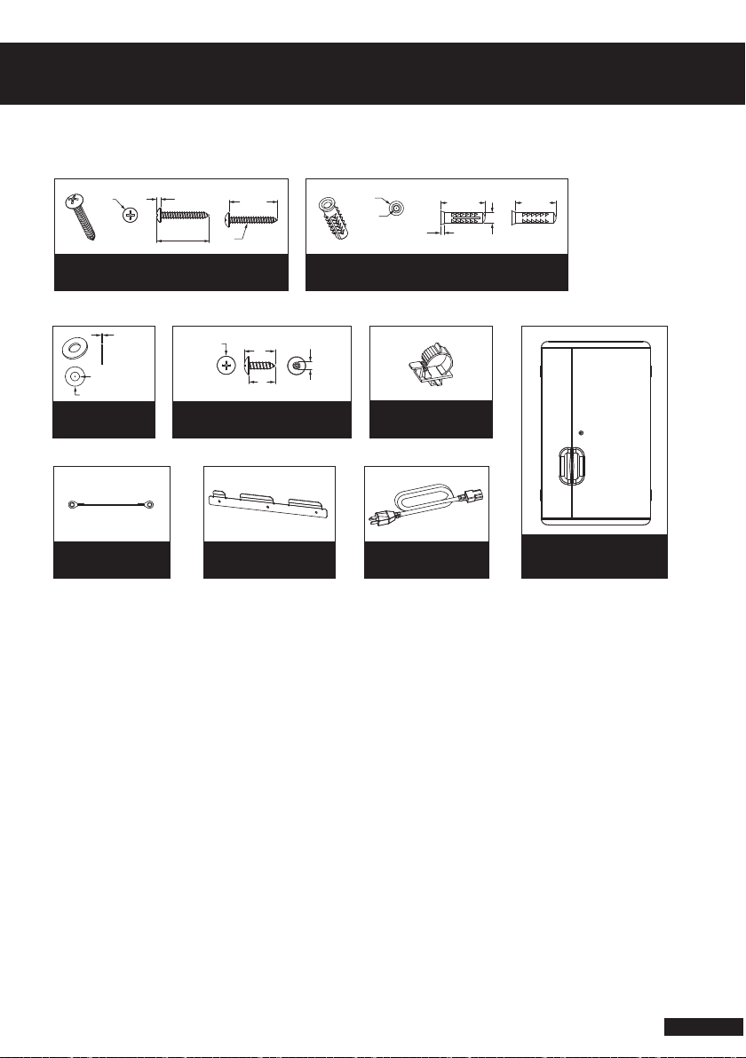
2. Components .............................................................................. 2
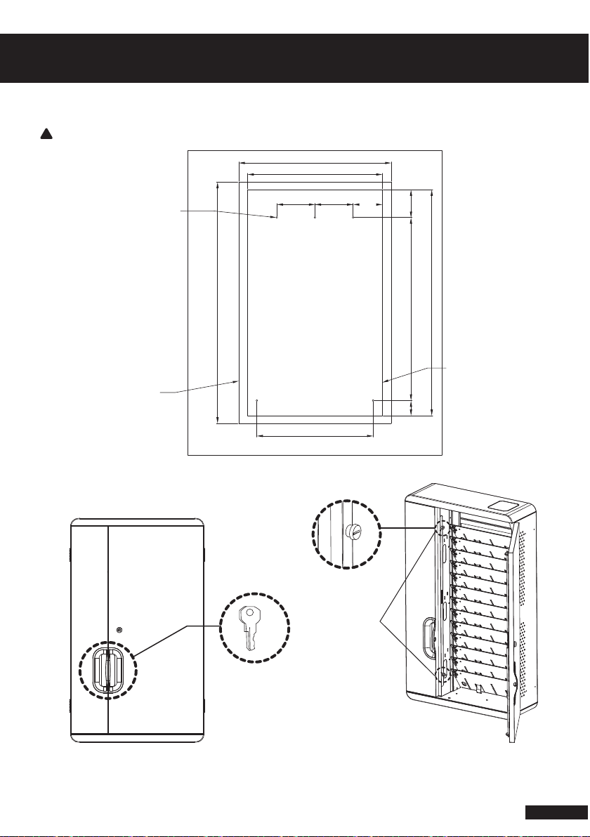
3. Space requirement .................................................................... 3
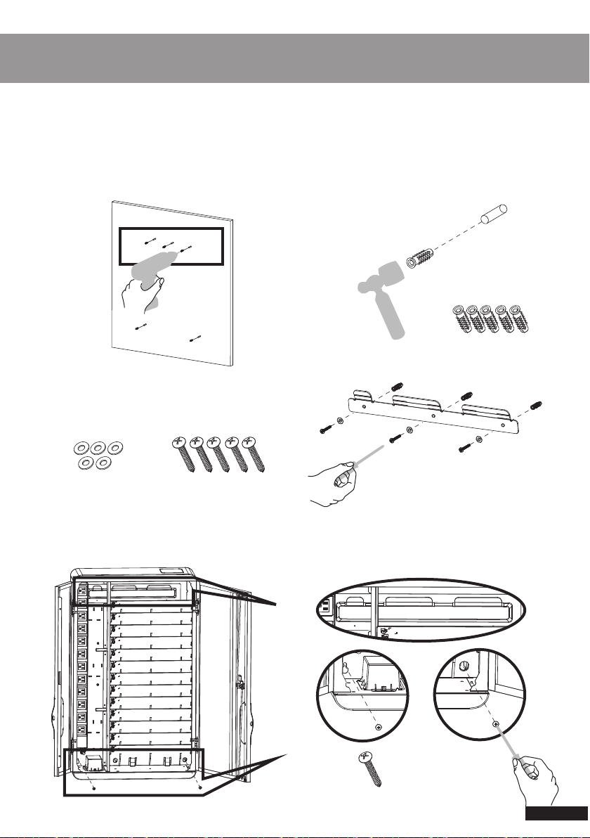
4. Setup .......................................................................................... 4, 5, 6, 7, 8, 9
5. Safety .........................................................................................10
The product is designed to charge up to 12 Chromebook®, Notebook ,
Laptops or Tablets, holds up to a 13.3 inch Displays Device
IMPORTANT SAFETY INSTRUCTIONS
When using an electrical mounting system , basic precautions should always be followed,
including the following : Read all instructions before using ( this mounting system )
DANGER – To reduce the risk of electric shock
1. Always unplug this mounting system from the electrical outlet before cleaning.
WARNING – To reduce the risk of burns, re, electric shock, or injury to persons
2. Unplug from outlet before putting on or taking o parts.
3. Use this mounting system only for its intended use as described in these instructions.
Do not use attachments not recommended by the manufacturer.
4. Never operate this mounting system if it has a damaged cord or plug . If it is not working
properly , return the mounting system to a service center for examination and repair.
5. Keep the cord away from heated surfaces.
6. Never operate the mounting system with the air opening blocked. Keep the air opening
free of lint, hair, etc...
7. Never drop or insert any object into any opening.
8. Do not use outdoor
9. Route cords and cables as shown in the installation instruction.
10. To disconnect, turn all controls to the o position, then remove plug from outlet.
11. For grounded products the following statement.
“WARNING: Risk of Electric Shock – Connect this mounting system to a properly grounded
outlet only. See Grounding instructions”
12. If a surface is not intended to support a video monitor such as televisions or computer
monitors, one of the following statements.
“Warning: Risk of injury to Persons – do not place video equipment such as televisions or
computer monitors on 2kg“ where the blank is lled in to identify the particular surface
“Warning: Risk of injury to Persons – do not use this mounting system to support video
equipment such as televisions or computer monitors”

1
Product SPEC
Model Name
Capacity
Cabinet Dim.
W22.44 x D7.08 x H35.03”
(530 x 180 x 890 mm)
12 Devices
Weight 17.09 kg
Volt® CW12
Input: AC 100-125V, 50/60Hz, 12A
AC 200-240V, 50/60Hz, 10A
Output: AC 100-125V, 50/60Hz, 12A
AC 200-240V, 50/60Hz, 10A
Power Specication
180mm530mm
890mm 890mm
Notice :
1. Weight of charging devices are required not more than 2kg.
2. Weight of AC adapters are required not more than 1kg.
Volt® CW12

2
2. Components
Self-tapping Screw x 5 pcs
T4 x L30mm, For Conctete
32.7mm
2.7mmØ9 30mm
T4
1mm
Washer x 5 pcs
For Conctete
IDØ5.5
ODØ12
Ground Wire 12 AWG x1
Ø11.3 Ø5
19mm
16mm
Self-tapping Screw x 5 pcs
T5 x L16mm, For Wooden
Ø3.8
Ø8.8
25.3mm
27.5mm
6.5mm
2.2mm
Nylon Wall Plug x5 pcs
dimension 1/4 x Depth 1
Wall Bracket x1 Power Cord x1
Power code holder x1
Volt CW12 x1

3. Space Requirement
3
Wall Mount Cabinet Space Requirement
Operation
600 (Operation Space)
950 (Operation Space)
890 (Cabinet Space)
Five Screw holes position
Wooden: directly screw
Concrete :Ø 1/4”x 1 depth
Operation Space
Cabinet Space
Hand Screws
M4 x L12mm
Take o the screws
To open the door
530 (Cabinet Space)
150 150
458
115
10972160
Use the key to open the door
Take o the Screws to open the Left door
x 2
Wooden Wall thickness Should be more 25mm
!

4
4. Set Up
Wall bracket
Hang on the bracket
Wood Screw x 3 pcs
T5 X L16mm
Wood Screw x 2 pcs
T5 X L16mm
█Mounting into Wooden wall
Follow the Cabinet Space Requirement
Screw into the Wooden Wall with T5 Screwier
Tools Needed (prepare by customer)
M
FT
Ø
Concrete

5
4. Using a Phillips driver (or a power driver with
a Phillips bit), attach the metal bracket and
hold the washers and screw T4 onto the wall
to x the cabinet.
5. Install the cabinet on the metal bracket.
And the same hold the washers and screw T4 onto the lower part of cabinet.
Washer x 5pcs Self-tapping Screw X 5pcs
T4 x L30mm
█Wall-mount to Concrete Wall
This is a team step.
1. Determine the installation points for your cabinet.
3. Insert the expansion bolt into the holes.2. Drill holes in the concrete wall about
5Ø 1/4” X 1” deep at the mounting points.
Expansion bolt x5 pcs
Install the bracket
Hold the washers
and screw T4 onto
the wall to x the
cabinet.

█Assembly Power Cord Holder
█Anti-Pull holder function
To x the power cord to Anti-Pull.
1. Tighten the Anti-Pull Holder on the power cord.
2. Insert the power cord into the
C13 Inlet of the cabinet.
3. Make sure the clip is facing to
the wall side.
Press to release the
power cord
Tighten the power cord
Pull up the clip to release xing the
power cord on the cabinet.
Attach to the wall
Front door
C13 Inlet
6

7
See Detail
█Cable Management
█Adapter Management

8
Take of the Screws
Take of the Screws
Option Holder
Adapter holder for
management
Power Strip move
to new position
█Power strip movable
█Optional
Adapter holder
Take of the Screws
Screw into new position

9
Setup
█Daisy-Chain
600 At least

●Always turn o the power to the produce before plugging IN or OUT.
●Do not unplug the power cord from the outlet when your hand are wet.
●Do not use cables that are damage.
●Do not unplug the cable into an extension cable
●Keep the door closed and locked when in use
●This product is designed to be used indoors only
●This product is not designed to be operated by a child or student
●Only Adult operation and supervision should move this product
●Do not allow anyone to set , stand , or climb on the product
●Move the product with caution
●Keep the product away from water
●Keep the ventilation holes unblock for air circulation
●Do not use the product to store liquids or cleaning supplier
●Disconnect the power cable from the wall before relocate the main unit
WARNING:
Ground Wire Setup
!
This product must only be used for its intended purpose in accordance with operating
instructions . Failure to observe the following notices can result it re , injury , death by
electric shock or equipment damage.
Class I Equipment. This equipment must be earthed. The power plug must be
connected to a properly wired earth ground socket outlet. An improperly wired
socket outlet could place hazardous voltages on accessible metal parts.
1. Screw out the screw
rst
2. Screw into the ground
wire 10
5. Safety

Rocstor
12979 Arroyo Street
San Fernando, CA, 91340
www.rocstor.com
+1 (818) 727 7000
Ver.1, Jun 2017
I.T.E.
E341990
Table of contents
Other Rocstor Batteries Charger manuals