ROCTEST PIL-10 User manual

OPERATION AND MAINTENANCE
MANUAL
POINT LOAD TESTER
Model PIL-10
©Roctest Limited, 2023. All rights reserved.
This product should be installed and operated only by qualified personnel. Its misuse is potentially dangerous. The Company makes no warranty as to the information furnished
in this manual and assumes no liability for damages resulting from the installation or use of this product. The information herein is subject to change without notification.
Tel.: 1.450.465.1113 • 1.877.ROCTEST (Canada, USA) • 33 (1) 64.06.40.80 (Europe) • www.roctest.com • www.telemac.fr
F1048B-230410

F1048B-230410 PIL-10
Page 1
TABLE OF CONTENTS
1INTRODUCTION .....................................................................................................2
2DESCRIPTION ........................................................................................................2
3TEST PROCEDURE................................................................................................3
3.1 Types of point load tests ...................................................................................3
3.2 Sample size frame configuration.......................................................................4
3.3 Operation..........................................................................................................6
4INTERPRETATION..................................................................................................9
5MAINTENANCE ....................................................................................................10
5.1 Plunger cleaning .............................................................................................10
5.2 Lubricating the pump.......................................................................................11
5.3 Oil change and air removal .............................................................................11
5.4 Keeping oil lines clean ....................................................................................13
5.5 Fixing small oil leaks.......................................................................................13
5.6 Spare parts list................................................................................................14
6TRANSPORTATION..............................................................................................15
7REFERENCES ......................................................................................................15
APPENDIX A................................................................................................................16
APPENDIX B................................................................................................................17
APPENDIX C................................................................................................................19

F1048B-230410 PIL-10
Page 2
1 INTRODUCTION
Point load tester model PIL-10 is a simple portable apparatus used for testing rock
samples or cores.
The PIL-10 has a maximum loading capacity of 10 metric tons and accepts drill cores or
rock lumps of different sizes having a maximum length of 102 mm.
The point load strength index obtained from a point load test is correlated with the
uniaxial compressive strength of the rock tested. Being rapid and simple to perform, the
point load test allows the user to easily delineate zones of rock of different strength
properties. It then becomes a most useful tool in large-scale mining as well as civil
engineering projects for classifying rock types from a mechanical perspective.
2 DESCRIPTION
The PIL-10 point load tester basically consists of the following components:
- a rigid loading frame onto which a fixed hydraulic jack provides the load for
bringing a rock disc to failure in between two conical end platens;
- a hand pump connected to a high-pressure hydraulic coupler onto which a
digital pressure gauge is also connected to a high-pressure hydraulic coupler
for failure load determination.
Protective cover
Conical platen
Hydraulic Cylinder
Pressure gauge
Hand pump

F1048B-230410 PIL-10
Page 3
The top conical end is fixed on the loading frame and the bottom one is mounted on the
piston of the hydraulic jack.
A ruler is fixed on the side of the loading frame and provides easy determination of the
core diameter.
The conical platen shape and tip radius follow the ISRM (International Society for Rock
Mechanics and Rock Engineering) “Suggested method for determining point load
strength”. A link toward a copy of this document is provided in appendix A. The user
should refer to the ISRM suggested method for details concerning the point load
strength test.
The capacity of the hydraulic jack is 100 kN, which corresponds to a pressure of 70 MPa
on the pressure gauge. The gauge has a pressure range of 100 MPa and features a
peak mode, which provides the failure load for the rock sample tested.
A removable protective cover with replaceable polycarbonate protective screens is fitted
over the top of the tester. The screens connect to a fix steel tray to create an enclosure
capable of containing rock debris and thus providing a clean and safe work environment.
3 TEST PROCEDURE
3.1Types of point load tests
Three points load test configurations are available for core logging.
Diametral test
This test is the most reproducible and is independent of the core length, provided
that the length/diameter ratio is equal to or greater than 1.0.
Axial test
When only rock discs are available or when discs are produced with the diametral
test, the axial test can be performed on core specimens with length/diameter ratios
between 0.3 and 1.0. This test is useful to evaluate strength anisotropy.
Irregular lump test
If irregularly shaped rock pieces are the only specimens available, tests can still be
performed on lumps having an equivalent core diameter close to 50 mm and an
overall approximately cubical shape. In order to fit this requirement, specimens
may be prepared from larger pieces using a saw or chisel.

F1048B-230410 PIL-10
Page 4
3.2 Sample size frame configuration
The apparatus can be configured in two ways to test samples from 14 to 102 mm.
Configuration 1 Configuration 2
Configuration
Sample size (mm)
1
14 to 67
2
50 to 102
Note : For samples sized 50 to 67 mm, it is recommended to favour the use of
configuration 1 in order to minimize piston extension. The hydraulic cylinder effective
area advance is 2.24 in2according to the Enerpac specifications.
Proceed as follows to get from configuration 2 to 1.
1. Unscrew both locking nuts.

F1048B-230410 PIL-10
Page 5
2. Slide off top beam sub-assembly.
3. Slide off both spacers.
4. Reassemble parts in this order. Locking nuts must be hand tightened only.
The apparatus is now ready for shorter samples. The ruler moved with the top beam and
provides the correct reading without the need for adjustment.

F1048B-230410 PIL-10
Page 6
3.3Operation
Note : On reception, the apparatus is saturated with oil and ready to be used. Before
using the pump, verify that all system fittings and connections are tight and leak free.
The following procedure is used to conduct the point load test with the PIL-10 tester.
1. Connect the hydraulic hose to the quick-connect coupling of the pump assembly.
2. Tighten the release valve located beside the pump support by turning the knob
clockwise. Use hand force only.
Release valve

F1048B-230410 PIL-10
Page 7
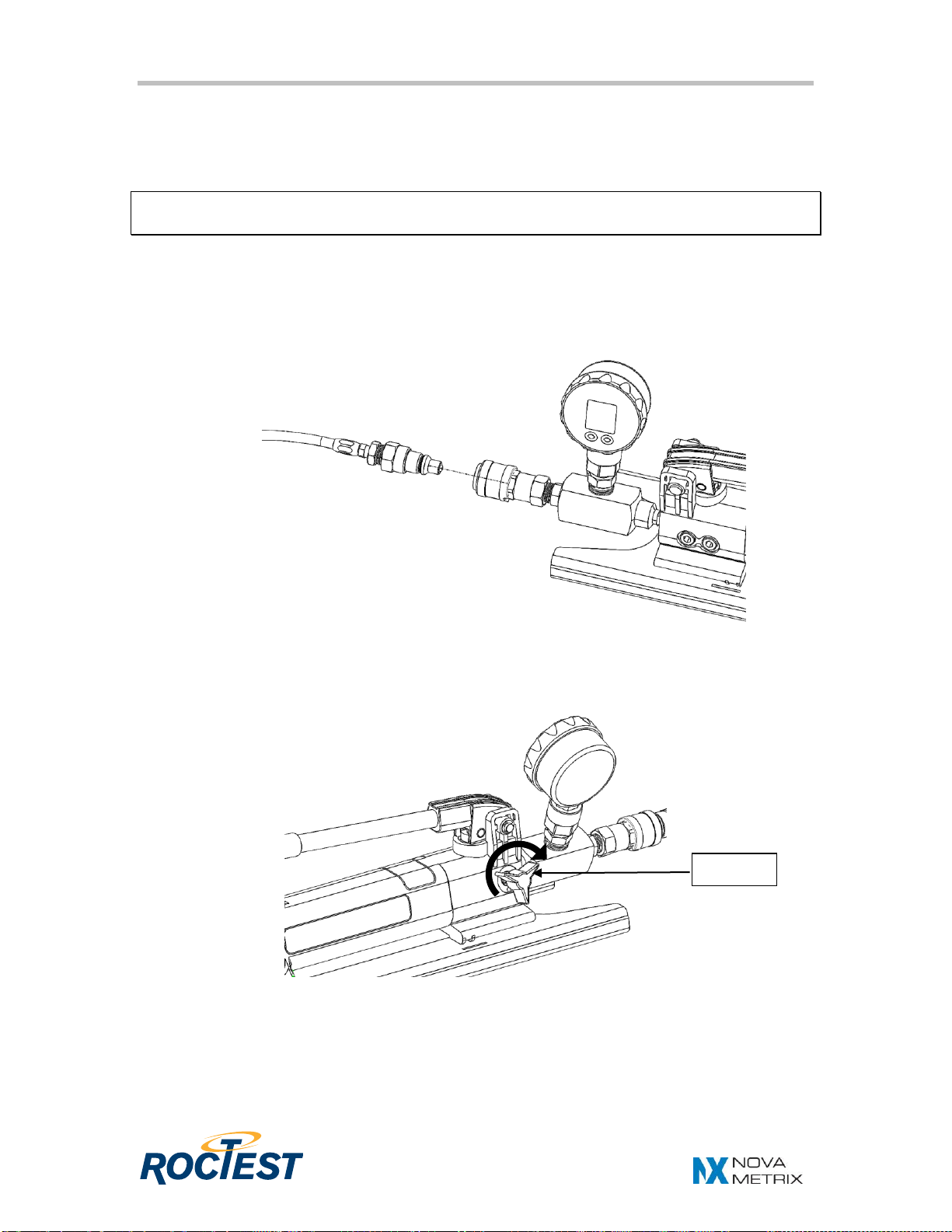
3. If the Keller pressure gauge is used, set the pressure gauge using the guide
provided in appendix C. Enter into the function menu, then:
- select the unit: 1(kN)*, bar, MPa or psi
- choose the peak on,
- set the zero.
*Note: The pressure gauge is delivered configured to display force in kilonewtons (kN)
based on the conversion factor established from calibration. It is represented by
unit 1which is active when the display alternates between 1 and the real-time
reading. The conversion factor cannot be edited from the pressure gauge menu.
If the APG PG7 pressure gauge is used, set the pressure gauge using the
guide provided in appendix D. Enter into the function menu, then:
- select the unit: kN**, bar, MPa or psi
- choose the peak « P HOLd » to enable the function Peak-Hold,
- set the zero
**Note: The pressure gauge is delivered configured to display force in kilonewtons (kN)
based on the conversion factor established from calibration. It is represented by
unit kN which is active when the screen displays the number 0.
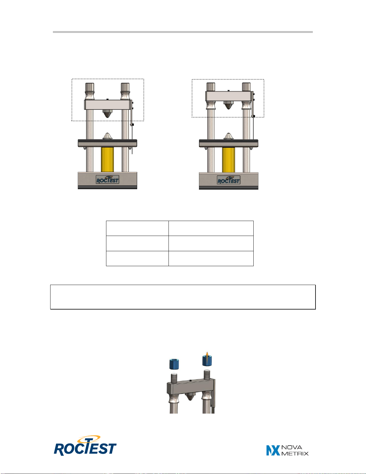
4. Place the rock sample on the lower platen and, using the pump lever, raise the
jack piston until the sample is in contact with the two platens. The contact
location depends on the type of test:
- for a diametral test, the platens must make contact with the core along its
diameter;
- for an axial test, contact with the core is made along a line perpendicular
to its end faces;
- for a lump test, contact is made along the smallest dimension of the lump,
away from edges and corners.
Using a two-speed pump: Under no load, the pump operates at rapid advance. When
the pump reaches 200 psi or 14 bar, you must momentarily stop pumping and raise the
handle to shift to high pressure stage. After the pump shifts, pumping takes less effort.
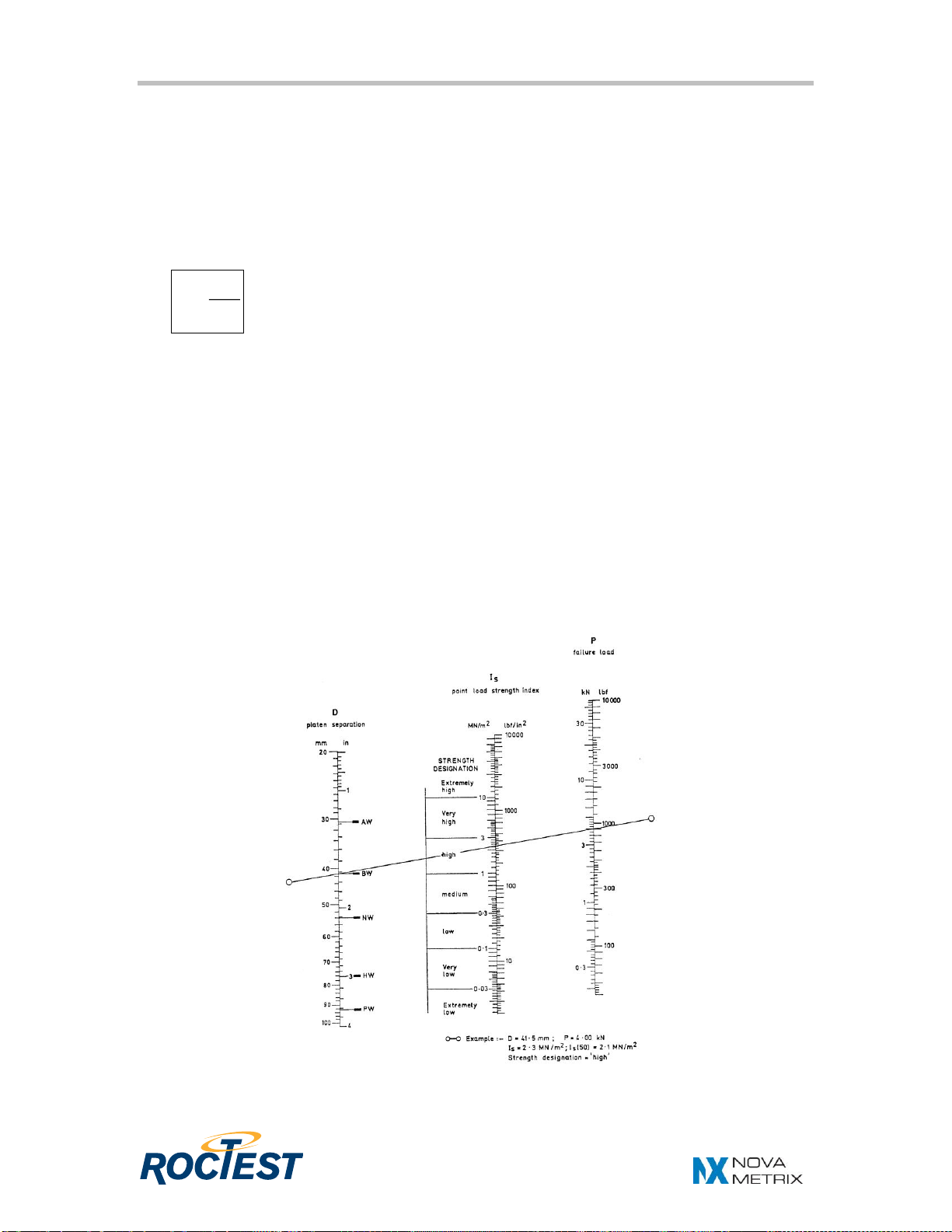
5. Read the distance separating the two contact point on the ruler fixed on the side
of the loading frame.
6. Place the protective enclosure over the top of the tester.
7. Increase load steadily such that failure occurs within 10 to 60 seconds.
NOTE: To reduce handle effort at high pressure, take short strokes. Maximum
leverage is obtained in the last 5° of stroke.

F1048B-230410 PIL-10
Page 8
8. If the Keller pressure gauge is used, record the reading at failure as shown on
the bottom number of the LEO 1 pressure gauge (the bottom number as to be set
to MAX). The top number of the LEO 1 manometer is the actual value in real time
and should not be used for calculations. The test is considered invalid and
rejected if the fracture surface passes through only one loading point.
If the APG PG7 pressure gauge is used, record the reading at failure by
selecting the key SEL. until it displays MAX on the screen. The test is considered
invalid and rejected if the fracture surface passes through only one loading point.
9. Remove the protective enclosure and larger rock fragments, then wipe off debris
from the tray.
10. Release the pressure by slowly turning the pump release valve counter
clockwise. The spring loaded piston will retract by itself.
Note : Reset the pressure gauge to zero between each test
Real time value
Max/Min value

F1048B-230410 PIL-10
Page 9
4 INTERPRETATION
The uncorrected point load strength index is calculated using the following relation and
the load value previously calculated.
where Isis the point load strength index [MPa]
Pis the load at failure [MN]
Deis the equivalent core diameter [m]
The index ISmay also be obtained graphically using the nomogram shown below
presented by Broch and Franklin (1972). The ISindex varies as a function of the
diameter of the core Din the diametral test and as a function of the equivalent diameter
Dein axial, block and irregular lump tests.
A size correction must be applied to obtain a unique point load strength value for the
rock sample and one that can be used for purposes of rock strength classification.
Please refer to the size correction procedure explained in the ISRM suggested method
given in appendix A. The same document also provides the method for evaluating the
uniaxial compressive strength of the rock tested from the corrected point load strength
index IS (50).
Nomogram for computing point load strength
D
P
=
Ie2
s

F1048B-230410 PIL-10
Page 10
5 MAINTENANCE
5.1Plunger cleaning
The piston jack needs to be cleaned frequently. Wipe off dust on piston jack using a lint-
free cloth and lubricate seal at the base of the piston jack with a few drops of Enerpac
hydraulic fluid HF100 regularly.
Disassemble the parts in the following sequence to gain access to the piston base:
1. Unscrew both locking nuts.
2. Lift off top beam assembly.
3. Unscrew lower platen.
4. Loosen set screws from side of middle plate.
5. Lift middle plate and tray assembly along the posts.
Do not use any grease with the apparatus.
Grease on the plunger will damage internal components of the jack.

F1048B-230410 PIL-10
Page 11
5.2Lubricating the pump
To extend the pump life, lubricate the beam pin (A), cross pin (B), and piston head (C)
regularly using roller bearing grease.
5.3Oil change and air removal
Oil change should be performed when oil is contaminated (turning black) to prevent
components wear. Enerpac recommends every 12 month or more often if the pump is
used in a dirty environment. Retract the plunger and open the Fill/vent cap. Drain the
used oil into a container and dispose of it according to regulations.
To fill the reservoir, make sure that the jack piston is fully retracted or the system will
contain more fluid than the pump reservoir can hold.
Fill/vent cap
B
C
A

F1048B-230410 PIL-10
Page 12
Follow the procedure below :
1. Turn the pump vent/fill cap to the open position and remove it from the reservoir.
2. Slowly add Enerpac hydraulic fluid. Fill reservoir only to level mark shown on the
back end of the pump.
The pump is non-vented and requires air in the reservoir to function properly.
Use only Enerpac hydraulic fluid HF100
otherwise damages can occur to the jack and its plunger.
Another type of fluid will void the warranty.
Hydraulic fluid can be provided by Roctest –Telemac (see spare parts list) or
directly from an Enerpac distributor.
3. Removing air from the system
a. Install reservoir cap in venting position and close release valve.
b. Place the PIL-10 upside down and hold the pump higher than the
cylinder.
c. Operate pump to fully extend the cylinder piston.

F1048B-230410 PIL-10
Page 13
d. Open release valve to retract the piston.
e. Return vent/fill cap to closed position.
Note : Frequent use of the quick acting coupler to disconnect the pump from the
hydraulic line can introduce air into the system. This will make the pumping
action feel inefficient. This can be easily solved by performing the above air
removal procedure.
5.4Keeping oil lines clean
When quick acting coupler halves are disconnected, always screw on clean dust caps.
Use every precaution to guard unit against entrance of dirt because foreign matter may
cause pump, cylinder, or valve failure.
5.5Fixing small oil leaks
If small oil leaks occur at hydraulic connections, unscrew the defective one, add some
Teflon tape, and tight it well.
Replenish any loss in hydraulic fluid and remove air from the system accordingly.

F1048B-230410 PIL-10
Page 14
5.6 Spare parts list
Description
Item number
Quantity
Protective screen
30-1048B03002
2
Protective screen screw #10-24
99-MCMA90909A518
12
Set of upper and lower conical platen
40-0048A40400
1
Locking nut
20-1048B02007
2
Spacer
20-1048B02006
2
Digital Pressure Gauge APG PG7
99-APG-PG7-10000
1
Ruler
10-1048B01001
1
Ruler screw ¼-20 x 3/8’’
05-V10SS030006
1
Rubber trim for frame base
10-1048B01002
2
Rubber trim for frame tray
10-1048B01003
2
Rubber trim for pump base
10-1048B01004
2
Enerpac Hydraulic jack RC102
05-H07RC102
1
Enerpac Manual Hand Pump P142
05-H07P142
1
Hydraulic hose with screw-on fittings
40-1048B40400
1
Bushing Adapter, 1/2 NPTF Male x 3/8 NPTF
Female
99-MCMA51205K353
1
Bushing Adapter, 3/8 NPTF Male x 1/4 NPTF
Female
99-MCMA51205K346
1
Straight Male to Male Connector 3/8 NPT
99-MCMA48805K851
2
Quick disconnect 3/8’’ coupling male
05-R22STFD3510020606
2
Quick disconnect 3/8’’ coupling female
05-R22STFD3510010606
2
Enerpac hydraulic oil
HF100,1 Quart
05-H07HF100
1
If the part you are looking for is not in this list. Send a picture and description to Roctest
for identification.

F1048B-230410 PIL-10
Page 15
6 TRANSPORTATION
The PIL-10 is sold in a custom made road case for ease of transportation. Before
loading the case, disconnect the pump assembly from the hose and make sure the
pump fill/vent cap is at close position.
Load the PIL-10 frame into the case carefully to avoid damage to the hydraulic line.
Make sure the hose is nicely rolled and tucked in the case opening intended for this
purpose. Close the lid and secure the latches. Avoid flipping the case over during
transportation. The total weight is 35 kg and handling must be done by two people to
reduce the risk of injuries.
7 REFERENCES
BROCH, E., and J.A. Franklin. The Point Load Strength Test, International Journal of
Rock Mechanics, Min. Sci., Vol. 9, 1992, pp. 669-697.

F1048B-230410 PIL-10
Page 17
APPENDIX B
GUIDE FOR DIGITAL MANOMETER KELLER MODEL LEO 1
KEY
FUNCTIONS
KEY
SELECT
ON
Wait for the instrument measuring mode (about 3 s).
SELECT
RESET
Max. / min. value and peak value are set to the actual
pressure.
ENTER
SELECT
OFF
Turns off the manometer.
ENTER
SELECT
MANO
Enter into manometer functions.
ENTER
SELECT
PEAK OFF / PEAK ON
Peak off: Normal measuring mode with 2
measurements per second.
Peak on: Fast measuring mode with 5000
measurements per second.
ENTER
SELECT
ZERO SET
Sets a new zero reference.
ENTER
SELECT
ZERO RES
Sets the zero to factory setting.
ENTER
SELECT
CONT ON / CONT OFF
Cont on: Deactivates the automatic turn-off
function.
Cont off: Activates the automatic turn-off function.
ENTER
SELECT
UNIT SELECTION
Bar
ENTER
SELECT
UNIT SELECTION
MPa
ENTER
SELECT
UNIT SELECTION
psi
ENTER
SELECT
UNIT SELECTION
1 (kN)
ENTER

F1048B-230410 PIL-10
Page 18
Exemple: Setting a new zero reference
•Turn on the manometer by shortly pressing the SELECT key.
•Press the SELECT key 3 times: MANO appears.
•Press ENTER: PEAK ON or PEAK OFF appears.
•Press SELECT: ZERO SET appears.
•Press ENTER: The new Zero reference is set.
•The manometer returns to the measuring mode.

F1048B-230410 PIL-10
Page 19
APPENDIX C
GUIDE FOR DIGITAL PRESSURE GAUGE APG PG7
Principle of operation of APG PG7 pressure gauge
Each of the three buttons on the PG7 performs multiple functions. The primary function
applies when in standard operating mode. The secondary functions are used for
programming operations and when special features, such as Peak-Hold, are enabled.
KEY
PRIMARY FUNCTION
SECONDARY FUNCTION
ON/OFF
Press and hold for 1 second to turn on
or off the gauge power.
Press once to access the main
setup menu
ZERO
Press to “zero” the gauge reading (the
reading must be less than 5% of full-
scale in order to zero the gauge).
Cycles through the options in the
setup menus.
SEL.
Cycles between the current,
maximum, and minimum pressure
readings.
Used to accept the displayed
option while in the setup menus.
Resets the peak-hold reading
when the peak-hold feature is
enabled.
The following figure shows all the available options to configure the pressure gauge. To
see the operator’s manual in full access, please visit the following link to find the
document :
https://www.apgsensors.com/sites/default/files/manuals/PG7-full-access-manual.pdf
APG PG7 pressure gauge configuration details
To configure the APG PG7 digital pressure gauge in a custom unit (tonnes, tons, kN,
newton, kg, lbs or lbf), a multiplier (or conversion factor) must be calculated using Pound
per Square Inch (psi) as the base unit of measure.
When configuring the pressure gauge, the kN unit has been registered with its own
multiplier based on the calibration of the PIL-10 Point Load Tester as well as the
conversion of the imperial unit lbf to the metric unit kN (1 lbf = 0.0044482216 kN). This
explains the mention « APG gauge custom kN unit multiplier: X.XXXX » on the
calibration certificate and product labels. If needed to enter again the kN multiplier in the
pressure gauge, please follow the instructions below to configure the PG7 pressure
gauge.
Table of contents
Other ROCTEST Test Equipment manuals