6. External Speed Control Connections
The following methods of remote power level control
can be utilized when desired:
A. CFR sensor can maintain a constant feedrate. Attach
the CFR sensor to terminals ACCEL “-“ (blue) and to
ACCEL “+” (brown). (Then update the software
settings. Sections 11-A and 13-B)
B. 4-20mA signal can be connected by bringing the
positive signal wire to 4-20 “+” and ground to 4-20 “-“.
(Update software settings. Sect 11-B)
C. 0-10VDC Analog input signal can be connected by
bringing the positive signal wire to 0-10V “+” and
ground to 0-10 “-“. (Update the software settings.
Section 11-C)
Software Adjustments
Once the electrical connections have been made, the
control can be turned on. The software settings can be
adjusted as desired through the control menu.
Display Messages
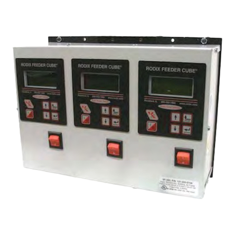
The normal operating display shows the status of the
control with regard to input signals and control settings.
See the Control Menu Layout pagefor display message
details.
Navigating The Control Menu
Thecontroluses four programmingkeystoprogramthe
control. The “I/0” key controls run, stop, and over-ride.
A. The ENTER key allows entry to the menu and
access to adjust each setting. Push and hold the
enter key to enter the program mode. If the security
feature has been enabled, enter the proper code.
Once inside the menu, the enter key selects a menu
item or a parameter to adjust. Any changes to the
settings are saved at power-down.
B. The BACK key moves the current menu location up
one level higher than it was before. It is also used to
get back to the normal operating display.
C. The Arrow Down key allows the user to step down
through the program menu or to decrease a setting.
D. The Arrow Up key allows the user to step up
through the program menu or to increase a setting.
E.The“1/0” key allows the user to temporarily stop orto
start the control’s operation. When the LCD status
reads “Stop/Run,” hold the “1/0” key down for just
overasecond, and thecontrol will starttheover-ride
operation. In over-ride mode the output turns on
regardless of I/O connections and status.
See the “Control Menu Layout” chart for the menu
structure. When in the menu mode and no keys are
pressedfor1 minute, thedisplayrevertstothe normal
operating display mode.
7. Amplitude Power Setting
The output power is controlled by the up and down
arrow keys. The power setting can be adjusted with
the keys unless the security feature lock has been
selected. Once the proper security code has been
entered,thepower setting maybe adjusted underthe
“Power” menu. Note: the power setting may not be
above the maximum power setting or below the
minimum power setting level. The amplitude power
setting is displayed in the following manner:
“A= 50.0%.”
8. Limiting The Maximum Output Of Control
The “Max Amplitude” setting can be adjusted to keep
a vibratory feeder from hammering or vibrating
excessively when the control is turned up to full
power. The maximum power setting can be found
under the “Power” menu. It can be adjusted from
100.0% down to 40.0%.
Caution: it is recommended when using the CFR
feature, that the Max output level of thecontrol should
be limited to prevent feeder coil from overheating.
The amplitude could continue to increase if the
system cannot get back to the desired vibration level.
9. Setting The Minimum Output of Control
The “Min Amplitude” setting can be adjusted to the
desired low level of vibration. The minimum power
setting can be found under the “Power” menu. It can
be adjusted up from 0.0% to 95.0%. Note: the
software does not allow the minimum level to be
within 5.0 counts of the maximum level.
10. Setting The Soft-Start
The start-up of the control’s output can be adjustedto
ramp up to the desired output level instead of starting
abruptly. Soft-start keeps parts from falling off the
tooling, reduces spring shock, and can eliminate
hammering when the control turns ON. The soft start
setting can be found under “Power Settings” menu.
The soft start can be set from 0.0 to 10.0 seconds.
When using the 2 speed operation, the soft start
function is active during the low to high speed
transition.
11. External Speed & Frequency Control
The feeder control’s power level can be controlled by
an external signal from a PLC, CFR sensor, or an
analog source. The “External Speed Connections”
section gives connection details.
A. When the Constant Feed Rate (CFR) sensor is
used, The “Amplitude Source” and “Frequency
Mode” settings should be set to “Auto Track.”
The control should display “Run/CFR” showing
that the sensor is connected. Set the power
setting to the desired feed rate. The control
uses information from the CFR sensor to
maintain a constant vibration level at the
resonate frequency. See the CFR instructions
page for more information.
Caution: it is recommended when using the CFR
feature, that the Max output level of the control
should be limited to prevent the feeder coil from
overheating. The amplitude could continue to
increase if the system cannot get back to the
desired vibration level.
B. 4-20mA signal from a PLC can be used to
remotely vary the output of the control instead of
the keypad. The “Amplitude Source” setting
must be set to 4-20mA to enable it. After the 4-
20mA feature is selected, the control will
automatically turn ON whenever a 4-20mA
signal is applied to the control (TB2 “+ 4-20” &
“-“). When the 4-20mA signal has been
removed, the amplitude setting resets to zero.
The 4-20mA menu selection allows a PLC to
controlboththe outputFrequencyand Amplitude
oronlythe Frequencyor justthe Amplitude. The
amplitude is controlled bythe 4-20mA input.The
Frequency is controlled by the 0-10VDC signal.
The signal adjusts a 100Hz range. The Min
Frequency adjustment specifies the frequency
used when the 0-10VDC input is at 0VDC. The
Max Frequency adjustment can be used to
ignore the upper end of the 0-10VDC signal.
C. 0-10VDC signal from a PLC can be used to
remotelyvarythe output ofthe control insteadof
the keypad. The “Amplitude Source” setting
mustbeset to 0-10VDCto enable it. Afterthe0-
10VDC feature is selected, the control will
automatically turn ON whenever a signal is
applied to the control (TB2- “+0-10” & “-“). When
the 0-10VDC signal has been removed, the
amplitude setting resets to zero.
D. When it is desirable to ignore the external speed
control inputs, the “Manual” setting can be
selected.
VF Application Note page 3_4 Ver1_28.doc 3/8/2013 Page 3
