Roger Technology ACS/BA/60 Product manual
ACS/BA/60 - ACS/BA/68
Attacco asta barriera sganciabile
Barrier BreakAway system
Istruzioni originali
IT - Istruzioni ed avvertenze per l’installatore
EN - Instructions and warnings for the installer
DE - Anweisungen und Hinweise für den Installateur
FR - Instructions et consignes pour l’installateur
ES - Instrucciones y advertencias para el instalador
PT - Instruções e advertências para o instalador
IS205 Rev.07 16/04/2021


3
1 Avvertenze generali 12
2 Descrizione del prodotto 12
3 Caratteristiche tecniche sensore magnetico 12
4 Installazione 12
4.1 Installazione BI/004 con ACS/BA/60 12
4.2
Installazione BI/001PC - BI/001PE - BI/004HP con
ACS/BA/60 12
4.3 Installazione BI/004 con ACS/BA/68 13
4.4 Installazione BI/001PC - BI/001PE - BI/004HP con
ACS/BA/68 13
5 Montaggio ACS/BA/60 - ACS/BA/68 in caso di
installazione già esistente 13
6 Collegamenti elettrici 14
7 Segnalazioni 14
8 Smaltimento 14
9 Informazioni aggiuntive e contatti 14
1 General safety precautions 15
2 Product description 15
3 Technical characteristics of the magnetic sensor 15
4 Installation 15
4.1 BI/004 installation with ACS/BA/60 15
4.2 BI/001PC - BI/001PE - BI/004HP installation with
ACS/BA/60 15
4.3 BI/004 installation with ACS/BA/68 16
4.4 BI/001PC - BI/001PE - BI/004HP installation with
ACS/BA/68 16
5 Assembly ACS/BA/60 - ACS/BA/68 in case of existing
installation 16
6 Electrical connections 17
7 Indicators 17
8 Disposal 17
9 Additional information and contact details 17
1 Allgemeine Sicherheitshinweise 18
2 Produktbeschreibung 18
3 Technische Eigenschaften Magnetsensor 18
4 Installation 18
4.1 Installation BI/004 mit ACS/BA/60 18
4.2 Installation BI/001PC - BI/001PE - BI/004HP mit
ACS/BA/60 18
4.3 Installation BI/004 mit ACS/BA/68 19
4.4 Installation BI/001PC - BI/001PE - BI/004HP mit
ACS/BA/68 19
5 Baugruppe ACS/BA/60 - ACS/BA/68 im Falle einer
bestehenden Installation 19
6 Elektrische Anschlüsse 20
7 Anzeigen 20
8 Entsorgung 20
9 Zusätzliche Informationen und Kontakte 20
1 Consignes générales de sécurité 21
2 Description du produit 21
3
Caractéristiques techniques du capteur magnétique
21
4 Installation 21
4.1 Installation de BI/004 avec ACS/BA/60 21
4.2 Installation de BI/001PC - BI/001PE - BI/004HP
avec ACS/BA/60 21
4.3 Installation de BI/004 avec ACS/BA/68 22
4.4 Installation de BI/001PC - BI/001PE - BI/004HP
avec ACS/BA/68 22
5 MontageACS/BA/60-ACS/BA/68encasd'installation
existante 22
6 Raccordements électriques 23
7 Signalisations 23
8 Élimination 23
9 Informations complémentaires et contacts 23
1 Advertencias generales 24
2 Descripción del producto 24
3 Características técnicas del sensor magnético
24
4 Instalación 24
4.1 Instalación BI/004 con ACS/BA/60 24
4.2 Instalación BI/001PC - BI/001PE - BI/004HP con
ACS/BA/60 24
4.3 Instalación BI/004 con ACS/BA/68 25
4.4 Instalación BI/001PC - BI/001PE - BI/004HP con
ACS/BA/68 25
5 Montaje ACS/BA/60 - ACS/BA/68 en caso de
instalación existente 25
6 Conexiones eléctricas 26
7 Señalizaciones 26
8 Eliminación 26
9 Información adicional y contactos 26
1 Advertências gerais 27
2 Descrição do produto 27
3 Características técnicas do sensor magnético
27
4 Instalação 27
4.1 Instalação BI/004 com ACS/BA/60 27
4.2 Instalação BI/001PC - BI/001PE - BI/004HP com
ACS/BA/60 27
4.3 Instalação BI/004 com ACS/BA/68 28
4.4 Instalação BI/001PC - BI/001PE - BI/004HP com
ACS/BA/68 28
5 Montagem ACS/BA/60 - ACS/BA/68 no caso de
instalação existente 28
6 Ligações elétricas 29
7 Sinalizações 29
8 Descarte 29
9 Informações adicionais e contatos 29
ITALIANO
ENGLISH
DEUTSCH
FRANÇAIS
ESPAÑOL
PORTUGUÊS
INDICE • INDEX • INDEX • INDEXER • ÍNDICE • ÍNDICE
4
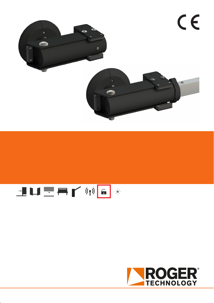
ACS/BA/60
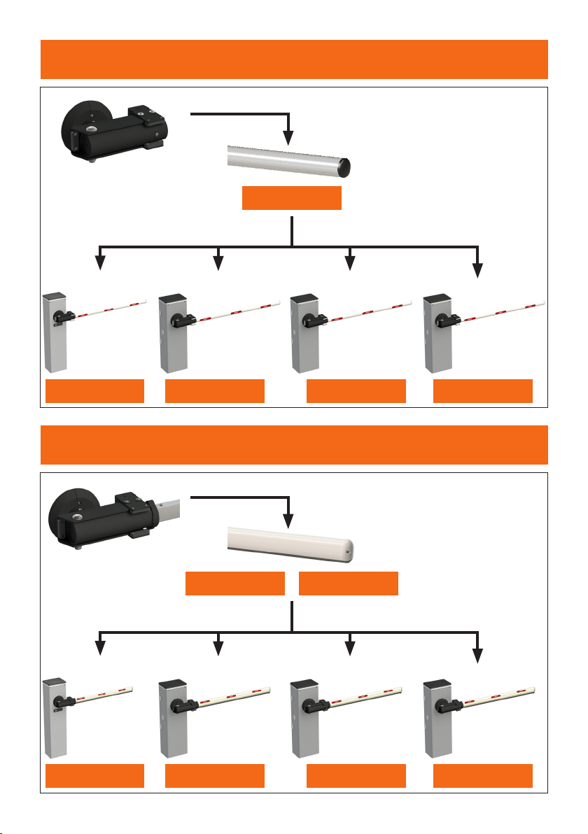
ACS/BA/68
BI/004
BI/004
BA/60/3
BA/68/3 BA/68/4
BI/001PC
BI/001PC
BI/001PE
BI/001PE
BI/004HP
BI/004HP
5
BI/004 with ACS/BA/60
I
M
L
A
C
D
H
G
Fx4
BA/60/3
E
~200
COVER
A
Bx12 (M10x16)
Bx12 (M10x16)
1
6
BI/001PC • BI/001PE • BI/004HP with ACS/BA/60
L
N
M
A
B
Cx4
Gx4
H
I
F
BA/60/3
D
E
~200
COVER
7
COVER
A
C
A
Bx12 (M10x16)
B
x12 (M10x16)
1
E
D
F
G
300 mm
H
Ix8
E
D
F
BI/004 with ACS/BA/68
G
300 mm
H
Ix8
80 mm
275 mm
80 mm
80 mm
35 mm
X
BA/68/3
BA/68/4
8
Q
S
R
N
x4
P
160 mm
Nx4
P
160 mm
M
L
ALED/4C

9
BI/001PC • BI/001PE • BI/004HP with ACS/BA/68
A
COVER
B
Cx4
E
D
F
80 mm
275 mm
80 mm
80 mm
35 mm
X
E
D
F
H
G
E
D
F
I
G
300 mm
H
Ix8
L
M
G
300 mm
H
Ix8
N
BA/68/3
BA/68/4
10
V
UT
L
PM
Q
N
x4
P
160 mm
R
Nx4
P
160 mm
S
ALED/4C
11
2
4
3
1
43
21
BI/001PE
BI/004
BI/004HP
BI/001PC
MONTAGGIO IN CASO DI INSTALLAZIONE GIÁ ESISTENTE
ASSEMBLY IN CASE OF EXISTING INSTALLATION
12
COM
+24V
COM
COM
+24V
+LAM
COM
+SC
10 11 12 13 14 15 16 17
+LUCI
marrone
brown
bianco
white
verde
green
COM
PED
PP
CH
AP
28 29 30 31 32
ORO
33
COM
34
verde
green
COM
+24V
COM
COM
+24V
+LAM
COM
+SC
10 11 12 13 14 15 16 17
+LUCI
marrone
brown
bianco
white
verde
green
COM
PED
PP
CH
AP
28 29 30 31 32
ORO
33
COM
34
verde
green
BI/004 • BI/004HP with CTRL
BI/001PC • BI/001PE with CTRL/P
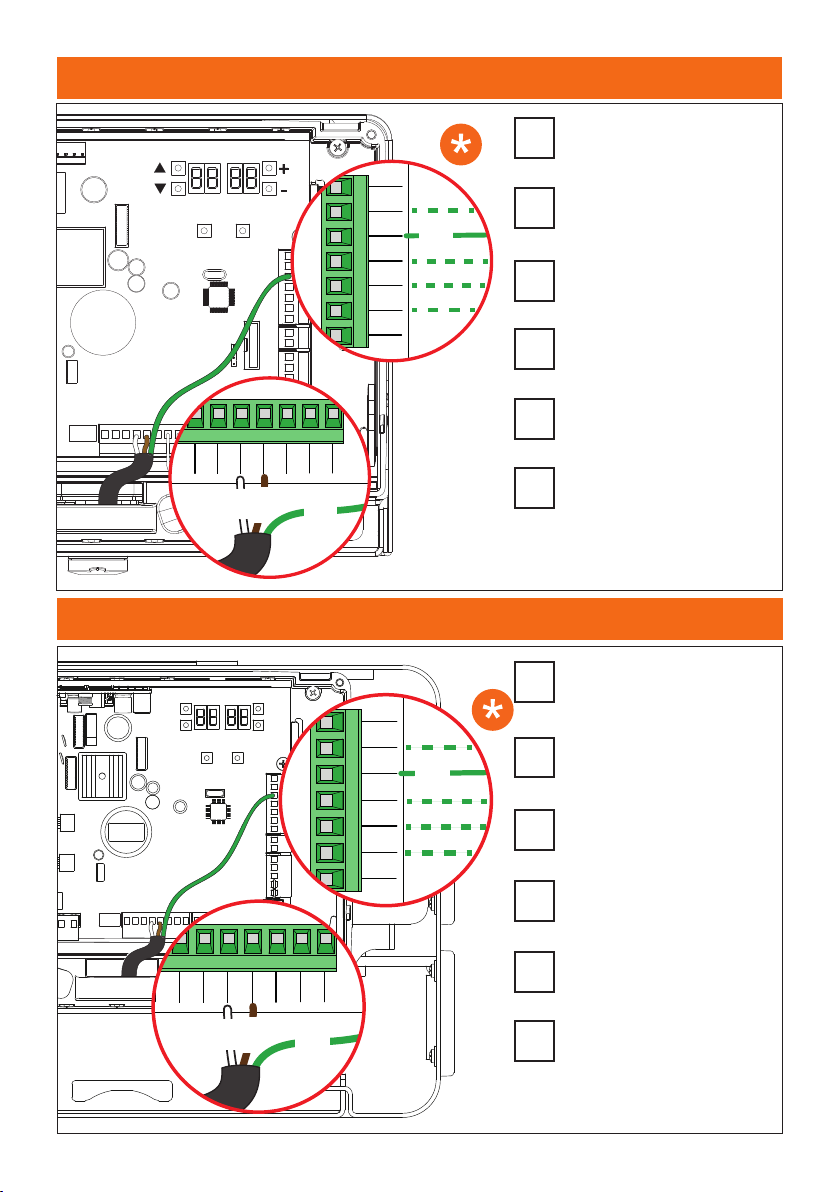
Collegare il lo verde ad uno degli
ingressi N.O. (ORO, AP, CH, PP,
PED) ed impostare correttamente il
parametro 19 sulla centrale.
Connect the green wire to one of the
N.O. inputs (ORO, AP, CH, PP, PED) and
set the parameter 19 correctly on the
control unit.
Das grün Kabel mit einem der N.O.-
Eingänge verbinden (ORO, AP, CH,
PP, PED) und den Parameter 19 am
Steuergerät richtig einstellen.
Connecter le l vert à l’une des entrées
N.O. (ORO, AP, CH, PP, PED) et régler
correctement le paramètre 19 sur la
centrale.
Conecte el cable verde a una de las
entradas N.O. (ORO, AP, CH, PP, PED) y
congure correctamente el parámetro
19 en la centralita.
Conecte o o verde a uma das
entradas
N.O. (ORO, AP, CH, PP, PED) e congure o
parâmetro corretamente
19 na unidade
de controlo.
IT
EN
DE
FR
ES
PT
Collegare il lo verde ad uno degli
ingressi N.O. (ORO, AP, CH, PP, PED) ed
impostare correttamente il parametro
19 sulla centrale.
Connect the green wire to one of the
N.O. inputs (ORO, AP, CH, PP, PED) and
set the parameter 19 correctly on the
control unit.
Das grün Kabel mit einem der N.O.-
Eingänge verbinden (ORO, AP, CH,
PP, PED) und den Parameter 19 am
Steuergerät richtig einstellen.
Connecter le l vert à l’une des entrées
N.O. (ORO, AP, CH, PP, PED) et régler
correctement le paramètre 19 sur la
centrale.
Conecte el cable verde a una de las
entradas N.O. (ORO, AP, CH, PP, PED) y
congure correctamente el parámetro
19 en la centralita.
Conecte o o verde a uma das
entradas
N.O. (ORO, AP, CH, PP, PED) e congure o
parâmetro corretamente
19 na unidade
de controlo.
IT
EN
DE
FR
ES
PT
13
F1
F2
F3 PROG TEST
+
-
BATTERY (+)
RECEIVER CARD
BATTERY CHARGER
SEC2
ENC2
ENC1
LOCKS
LED LIGHT
SEC1
BATTERY (-)
123456
Y
X
M
Z
7 8
COM
COM
+24V
+ES
+LAM
COM
COM
LNA
LNB
+SC
10 11 12 13 14 15 16 17
18 19 20
+LUCI
ST
COM
COS
FT
COM
ANT
21 22 23 24 25
COM
PED
PP
CH
AP
28 29 30 31 32
ORO
33
COM
3426 27
9
ACCESA
ON
SPENTA
OFF
ALLARME
ALARM
OK
...
...
F1
F2
F3 PROG TEST
+
-
BATTERY (+)
RECEIVER CARD
BATTERY CHARGER
SEC2
ENC2
ENC1
LOCKS
LED LIGHT
SEC1
BATTERY (-)
123456
Y
X
M
Z
7 8
COM
COM
+24V
+ES
+LAM
COM
COM
LNA
LNB
+SC
10 11 12 13 14 15 16 17
18 19 20
+LUCI
ST
COM
COS
FT
COM
ANT
21 22 23 24
25
COM
PED
PP
CH
AP
28 29 30 31 32
ORO
33
COM
3426 27
9
CHIUSO
CLOSED
APERTO
OPENED
Relay 24V
14
IT
1 Avvertenze generali
Attenzione: unaerratainstallazione
può causare gravi danni. Leggere
attentamente le istruzioni prima di
iniziare l’installazione del prodotto.
Il presente manuale di installazione è rivolto
esclusivamente a personale qualicato.
ROGER TECHNOLOGY declina qualsiasi
responsabilità derivante da un uso improprio o
diverso da quello per cui è destinato ed indicato
nel presente manuale.
L’installazione, i collegamenti elettrici e le regolazioni
devono essere effettuati da personale qualicato
nell’osservanza della Buona Tecnica ed in
ottemperanza alle normative vigenti. Prima di iniziare
l’installazione vericare l’integrità del prodotto.
Togliere l’alimentazione elettrica, prima di qualsiasi
intervento.
Per l’eventuale riparazione o sostituzione dei prodotti
dovranno essere utilizzati esclusivamente ricambi
originali. I materiali dell’imballaggio (plastica,
polistirolo, ecc.) non vanno dispersi nell’ambiente e
non devono essere lasciati alla portata dei bambini
in quanto potenziali fonti di pericolo.
ATTENZIONE! La manipolazione delle parti
elettroniche e dei conduttori deve essere
effettuata con la massima cautela, in quanto
trattasi di dispositivi sensibili alle scariche
elettrostatiche.
2 Descrizione del prodotto
L'attacco asta ACS/BA/60 - ACS/BA/68 è un dispositivo
di sicurezza per sganciare le aste delle barriere BIONIK.
A seguito di un urto contro l'asta, il sistema si sgancia
evitando che l'asta stessa e la barriera subiscano gravi
danni. Il sensore magnetico integrato interrompe il
funzionamento dell'automazione.
L'attacco asta sganciabile ACS/BA/60 - ACS/BA/68 è
utilizzabile con revisione rmware r3.50 (o successive)
della centrale di comando CTRL oppure con la revisione
c1.30 (o successive) della centrale di comando CTRL/P.
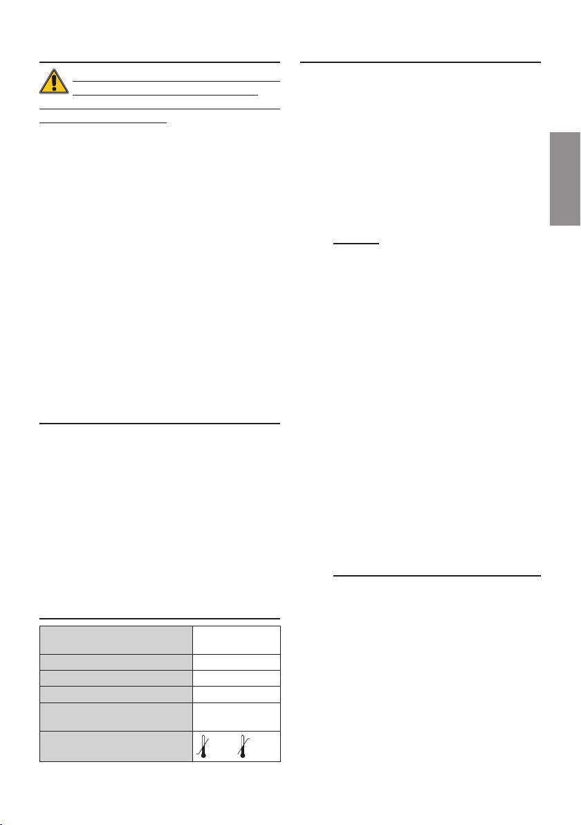
3 Caratteristiche tecniche
sensore magnetico
TECNOLOGIA ADOTTATA Sensore a effetto
HALL, unipolare
TENSIONE DI ALIMENTAZIONE 24Vdc ±15%
ASSORBIMENTO CORRENTE 8mA
TIPOLOGIA DI USCITA Open Collector
MASSIMA TENSIONE
APPLICABILE ALL'USCITA 12Vdc
TEMPERATURA DI
FUNZIONAMENTO
-20°C +55°C
4 Installazione
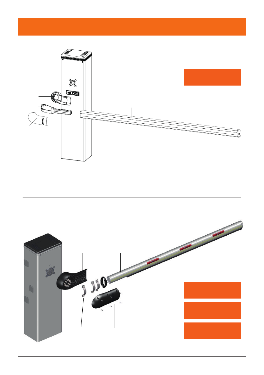
Il sistema ACS/BA/60 utilizza l'asta tonda BA/60/3 no
a 3 metri di lunghezza.
ll sistema ACS/BA/68 utilizza l'asta ellittica BA/68/3
no a 3 metri di lunghezza, BA/68/4 no a 4 metri di
lunghezza.
Per installare il sistema ACS/BA/60 vedi pag. 3 per BI/004
oppure pag.4 per BI/001/PC - BI/001/PE, BI/004HP.
Per installare il sistema ACS/BA/68 vedi pag. 5-6 per
BI/004 oppure pag. 7-8 per BI/001/PC - BI/001/PE -
BI/004HP.
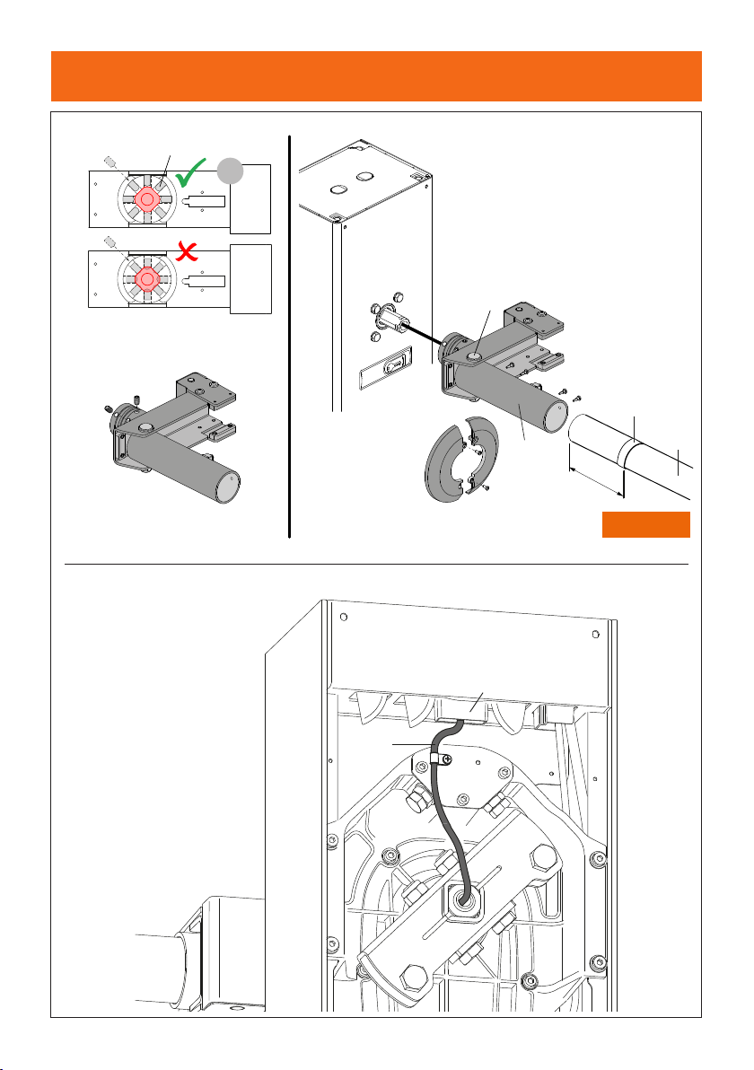
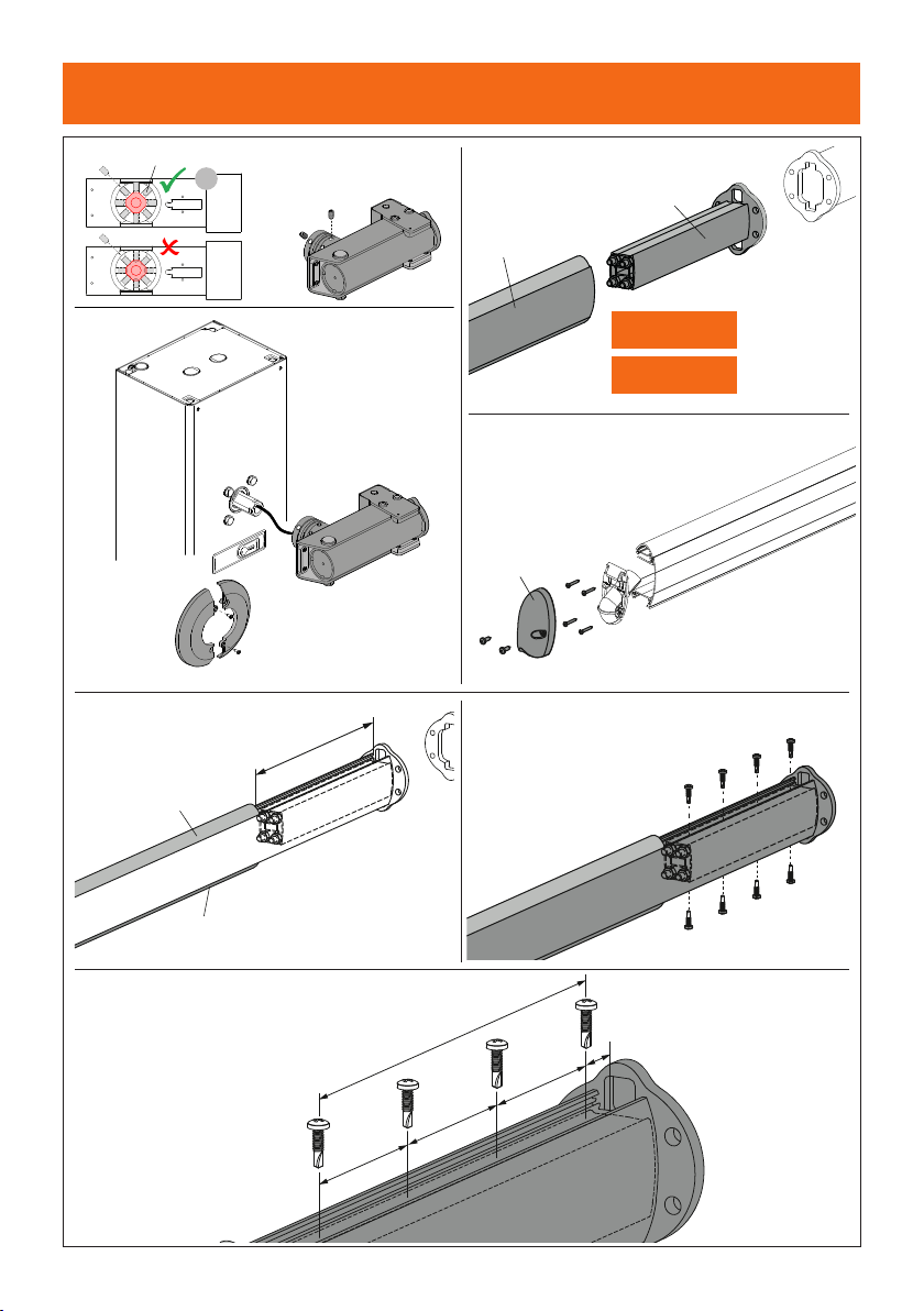
4.1 Installazione BI/004 con ACS/BA/60
(pag. 5)
1. Passare il cavo di collegamento attraverso l'albero
motore e farlo uscire dal lato opposto.
2. Avvitare parzialmente le 12 viti [B] M10x16 come
indicato nel dettaglio 1.
3. Inserire il supporto asta [A] all'albero motore.
4. Stringere le 12 viti [B] M10x16 no a completo
ssaggio.
5. Inserire l'asta [C] BA/60/3 all'interno della staffa
cilindrica [E] e ssarla con le 4 viti autoforanti [F].
NOTA: Prima di inserire l'asta nella staffa, applicare il
nastro adesivo [D] in dotazione.
6. Inlare l'asta completa all'interno del supporto asta
[A] e ssarla con la vite [G] M12x100.
7. Posizionare la copertura [H] e ssarla con le 2 viti in
dotazione.
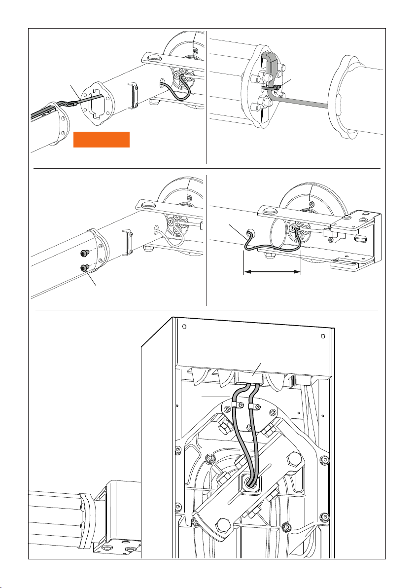
8. Far passare il cavo di collegamento attraverso il
centro del bilanciere [dettaglio I].
9. Fissare il cavo con il fermacavo presente nella
struttura portante della barriera [dettaglio L]
10. Introdurre il cavo all'interno della centrale di comando
[dettaglio M], evitando che crei disturbo al movimento
dell'automazione.
11. Procedere con i collegamenti elettrici.
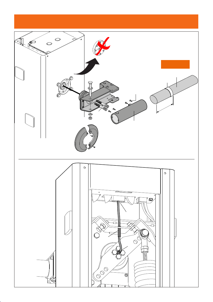
4.2 Installazione BI/001PC - BI/001PE -
BI/004HP
con ACS/BA/60 (pag. 6)
1. Rimuovere la angia [A] dall'albero motore.
NOTA: Il prodotto deve essere smaltito sempre
da personale tecnico qualicato utilizzando le
procedure idonee. Eseguire la “raccolta separata”
per lo smaltimento secondo i metodi previsti dai
regolamenti locali.
2. Passare il cavo di collegamento attraverso l'albero
motore e farlo uscire dal lato opposto.
3. Fissare il supporto asta [B] all'albero motore con le 4
viti [C] M12x80.
4. Inserire l'asta [D] BA/60/3 all'interno della staffa
cilindrica [F] e ssarla con le 4 viti autoforanti [G].
NOTA: Prima di inserire l'asta nella staffa, applicare il
nastro adesivo [E] in dotazione.

15
IT
5. Inlare l'asta completa all'interno del supporto asta
[B] e ssarla con la vite [H] M12x100.
6. Posizionare la copertura [I] e ssarla con le 2 viti in
dotazione.
7. Far passare il cavo di collegamento attraverso il
guidacavo al centro del bilanciere [dettaglio L].
8. Introdurre il cavo all'interno del guidacavo in gomma
presente nella struttura portante della barriera
[dettaglio M].
9. Introdurre il cavo all'interno della centrale di comando
[dettaglio N], evitando che crei disturbo al movimento
dell'automazione.
10. Procedere con i collegamenti elettrici.
4.3 Installazione BI/004 con ACS/BA/68
(pag. 7)
1. Passare il cavo di collegamento attraverso l'albero
motore e farlo uscire dal lato opposto.
2. Avvitare parzialmente le 12 viti [B] M10x16 come
indicato nel dettaglio 1.
3. Inserire il supporto asta [A] all'albero motore.
4. Stringere le 12 viti [B] M10x16 no a completo
ssaggio.
5. Posizionare la copertura [C] e ssarla con le 2 viti in
dotazione.
6. Inserire la staffa [D] all'interno dell' asta BA/68/3 o
BA/68/4 [E].
7. Togliere il tappo [F] e il supporto del tappo.
8. Slare il copri led superiore [G] e la gomma antiurto
[H] di 300 mm.
9. Fissare l'asta con le 8 viti autoforanti 4,8x19 [I]
mantenendo una distanza come indicato nel
dettaglio X.
10. Far passare la strip led [L] all'interno del copri led
no all'albero motore e farlo uscire dal lato opposto.
Riposizionare copri led e gomma antiurto e ssare il
tappo con le viti.
11. Fissare il cavo con la fascetta in dotazione [M].
12. Fissare l'asta e la staffa al supporto ACS/BA/68 con
le 4 viti M8x16 [N].
13. Aprire ACS/BA/68 di 180° e lasciare una lunghezza
cavo visibile di 160mm [P]. NOTA: il cavo NON deve
essere teso.
14. Far passare il cavo di collegamento attraverso il
centro del bilanciere [dettaglio Q].
15. Fissare il cavo con il fermacavo presente nella
struttura portante della barriera [dettaglio R]
16. Introdurre il cavo all'interno della centrale di comando
[dettaglio S], evitando che crei disturbo al movimento
dell'automazione.
17. Procedere con i collegamenti elettrici.
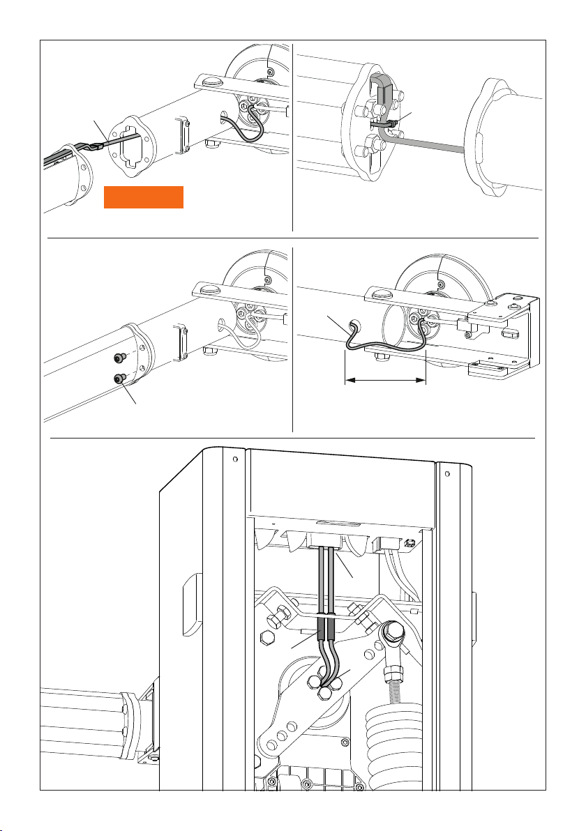
4.4 Installazione
BI/001PC - BI/001PE -
BI/004HP
con ACS/BA/68 (pag. 9)
1. Rimuovere la angia [A] dall'albero motore.
NOTA: Il prodotto deve essere smaltito sempre
da personale tecnico qualicato utilizzando le
procedure idonee. Eseguire la “raccolta separata”
per lo smaltimento secondo i metodi previsti dai
regolamenti locali.
2. Passare il cavo di collegamento attraverso l'albero
motore e farlo uscire dal lato opposto.
3. Fissare il supporto asta [B] all'albero motore con le 4
viti [C] M12x80.
4. Posizionare la copertura [D] e ssarla con le 2 viti in
dotazione.
5. Inlare il supporto asta [E] e ssarla con la vite [F]
M12x100.
6. Inserire la staffa [G] all'interno dell' asta BA/68/3 o
BA/68/4 [H].
7. Togliere il tappo [I] e il supporto del tappo.
8. Slare il copri led superiore [L] e la gomma antiurto
[M] di 300 mm.
9. Fissare l'asta con le 8 viti autoforanti 4,8x19 [N]
mantenedo una distanza come indicato nel dettaglio X.
10. Far passare la strip led [P] all'interno del copri led
no all'albero motore e farlo uscire dal lato opposto.
Riposizionare copri led e gomma antiurto e ssare il
tappo con le viti.
11. Fissare il cavo con la fascetta in dotazione [Q].
12. Fissare l'asta e la staffa al supporto ACS/BA/68 con
le 4 viti M8x16 [R].
13. Aprire ACS/BA/68 di 180° e lasciare una lunghezza
cavo visibile di 160mm [S]. NOTA: il cavo NON deve
essere teso.
14. Far passare il cavo di collegamento attraverso il
centro del bilanciere [dettaglio T].
15. Fissare il cavo con il fermacavo presente nella
struttura portante della barriera [dettaglio U]
16. Introdurre il cavo all'interno della centrale di comando
[dettaglio V], evitando che crei disturbo al movimento
dell'automazione.
17. Procedere con i collegamenti elettrici.
5 Montaggio ACS/BA/60 -
ACS/BA/68 in caso di
installazione già esistente
(pag. 11)
BI/004
1. Rimuovere il carter [1].
2. Rimuovere l'asta [2].
3. Rimuovere il supporto del braccio bionico [3].
4. Rimuovere il carter [4].
Per installare l'attacco asta ACS/BA/60 seguire il
capitolo 4.1.
Per installare l'attacco asta ACS/BA/68 seguire il
capitolo 4.3.
BI/001PC - BI/001PE - BI/004HP
1. Rimuovere il carter [1].
2. Rimuovere le ange di supporto [2].
3. Rimuovere l'asta [3].
4. Rimuovere la angia dell'asta di ssaggio dell'albero
motore [4].
16
Per installare l'attacco asta ACS/BA/60 seguire il
capitolo 4.2.
Per installare l'attacco asta ACS/BA/68 seguire il
capitolo 4.4.
6 Collegamenti elettrici (pag. 12)
Effettuare i collegamenti alla centrale di comando come
indicato a pag. 10-11.
Collegare il lo verde a uno degli ingressi di comando
(AP, CH, PP, PED o ORO), il lo marrone al morsetto +24
e il lo bianco al morsetto COM.
ATTENZIONE! ABILITARE L'INGRESSO DI COMANDO
(AP, CH, PP, PED O ORO) AL PARAMETRO 19 SULLA
CENTRALE.
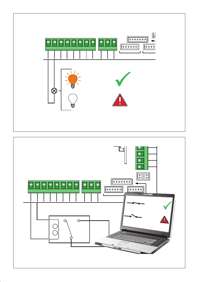
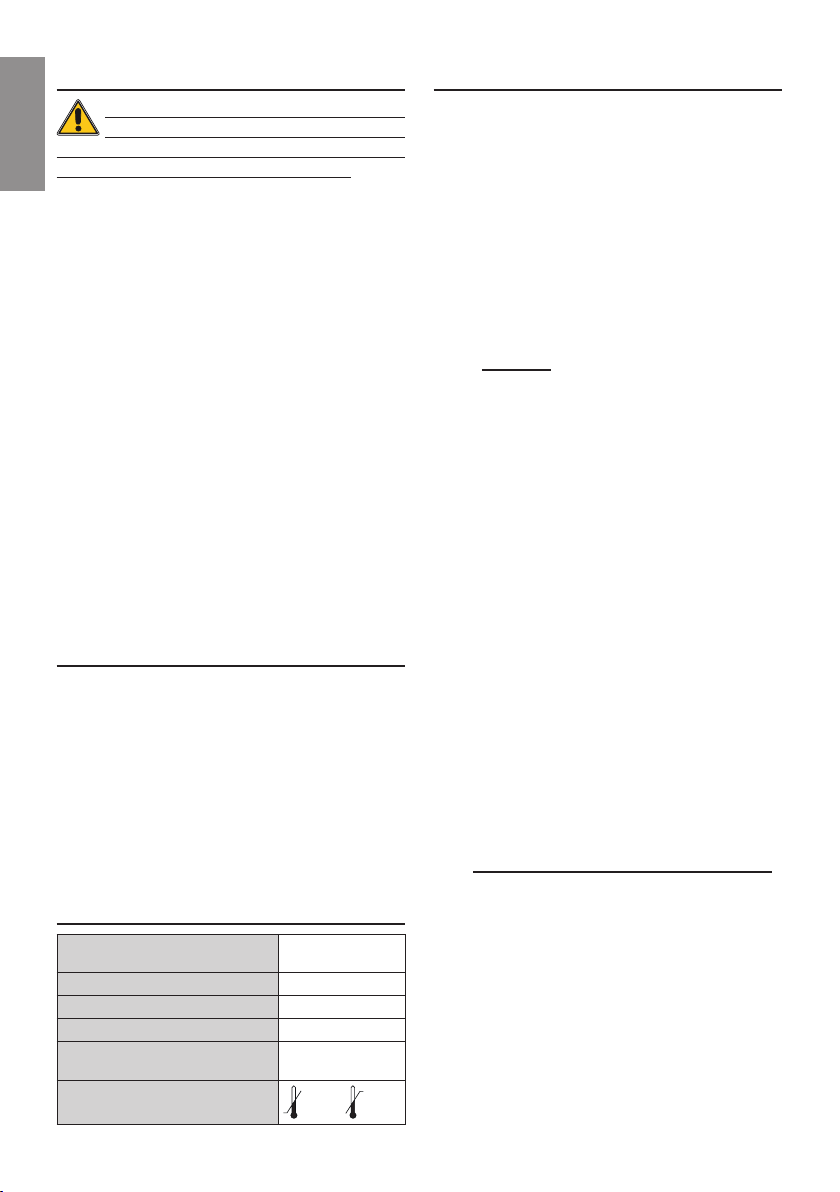
È possibile collegare una lampada spia all'uscita SC
per la segnalazione di eventuali anomalie oppure,
collegando un relay, è possibile avere un contatto puro
di segnalazione ad un sistema di controllo esterno (pag.
11).
Per eventuali altre congurazioni e regolazioni fare
riferimento al manuale della centrale di comando CTRL,
CTRL/P.
7 Segnalazioni
Segnalazione modalità TEST
DISPLAY POSSIBILE CAUSA INTERVENTO
00 br Sensore attacco asta
sganciabile attivato,
oppure non collegato o
collegamento errato.
Vericare le imposta-
zioni del parametro 19.
Vericare il corretto col-
legamento del sistema
alla centrale.
Segnalazione allarmi e anomalie
DISPLAY POSSIBILE CAUSA INTERVENTO
brEA Sensore attacco asta
sganciabile in allarme. Vericare l’impostazio-
ne di par. 19.
Vericare il corretto col-
legamento del sistema
alla centrale.
Riagganciare l’asta.
Valutare la sostituzione
dell’asta se danneg-
giata.
8 Smaltimento
Il prodotto deve essere smaltito sempre da
personale tecnico qualicato utilizzando le
procedure idonee. Questo prodotto è
costituito da vari tipi di materiali, alcuni
possono essere riciclati altri devono essere
smaltiti attraverso sistemi di riciclaggio o
smaltimento previsti dai regolamenti locali per questa
categoria di prodotto.
É vietato gettare questo prodotto nei riuti domestici.
Eseguire la “raccolta separata” per lo smaltimento
secondo i metodi previsti dai regolamenti locali; oppure
riconsegnare il prodotto al venditore nel momento
dell’acquisto di un nuovo prodotto equivalente.
Regolamenti locali possono prevedere pesanti sanzioni
in caso di smaltimento abusivo di questo prodotto.
Attenzione! Alcune parti del prodotto possono contenere
sostanze inquinanti o pericolose, se disperse potrebbero
provocare effetti dannosi sull’ambiente e sulla salute
umana.
9 Informazioni aggiuntive e
contatti
Tutti i diritti relativi alla presente pubblicazione sono di
proprietà esclusiva di ROGER TECHNOLOGY. ROGER
TECHNOLOGY si riserva il diritto di apportare eventuali
modiche senza preavviso. Copie, scansioni, ritocchi
o modiche sono espressamente vietate senza un
preventivo consenso scritto di ROGER TECHNOLOGY.
SERVIZIO CLIENTI ROGER TECHNOLOGY:
attivo: dal lunedì al venerdì
dalle 8:00 alle 12:00 - dalle 13:30 alle 17:30
Telefono: +39 041 5937023
E-mail: [email protected]
Skype: service_rogertechnology
17
EN
1 General safety precautions
Warning: incorrect installation may
cause severe damage or injury.
Read the instructions carefully before
installing the product.
This installation manual is intended for qualied
personnel only. ROGER TECHNOLOGY cannot be
held responsible for any damage or injury due to
improper use or any use other the intended usage
indicated in this manual.
Installation, electrical connections and
adjustments must be performed by qualied
personnel, in accordance with best practices and
in compliance with applicable regulations. Before
installing the product, make sure it is in perfect
condition.
Disconnect the mains electrical power before
performing any work. Only use original spare parts
when repairing or replacing products.
The packaging materials (plastic, polystyrene,
etc.) should not be discarded in the environment or
left within reach of children, as they are a potential
source of danger.
WARNING! Handle electronic parts and
terminals with extreme care, as these parts are
highly sensitive to static electricity.
2 Product description
The boom connection ACS/BA/60 - ACS/BA/68 is a
safety device for disengaging the booms of the BIONIK
barriers.
Following an impact to the boom, the system disengages,
protecting the boom and the barrier against serious
damage. The built-in sensor interrupts the operation of
the automation system.
The connection of the detachable boom ACS/BA/60 -
ACS/BA/68 can be used with the rmware version r3.50
(or later) of the control unit CTRL or with the rmware
version c1.30 (o later) of the control unit CTRL/P.
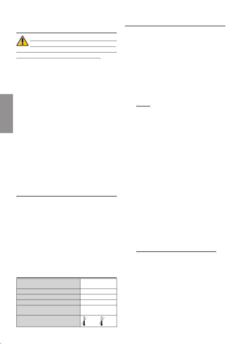
3 Technical characteristics of
the magnetic sensor
TECHNOLOGY USED Unipolar, HALL
effect sensor
MAINS POWER VOLTAGE 24Vdc ±15%
CURRENT ABSORPTION 8mA
OUTPUT TYPE Open Collector
MAXIMUM VOLTAGE
APPLICABLE AT THE OUTPUT 12Vdc
OPERATING TEMPERATURE -20°C +55°C
4 Installation
The ACS/BA/60 system uses the BA/60/3 round boom,
up to 3 meters in length.
The ACS/BA/68 system uses the BA/60/3 elliptical
boom, up to 3 meters in length, BA/60/4 elliptical boom,
up to 4meters in length.
To install the ACS/BA/60, see pag 3 for BI/004 or pag 4
for BI/001PC - BI/001PE - BI/004HP.
To install the ACS/BA/68, see pag 5-6 for BI/004 or pag
7-8 for BI/001PC - BI/001PE - BI/004HP.
4.1 BI/004 installation with ACS/BA/60
(pag. 5)
1. Pass the connecting cable through the crankshaft
and make it come out from the opposite side.
2. Partially tighten the 12 screws [B] M10x16 as shown
in detail 1.
3. Insert the rod holder [A] into the motor shaft.
4. Tighten the 12 screws [B] M10x16 until fully secured.
5. Insert the boom [C] BA/60/3 in the cylindrical bracket
[E] and fasten it with the 4 self-tapping screws [F].
NOTE: Before inserting the boom into the bracket,
apply the supplied adhesive tape [D].
6. Insert the rod fully inside the rod support [A] and
fasten it with the screw [G] M12x100.
7. Put the cover [H] and fasten it with the 2 screws
supplied.
8. Pass the connecting cable through the centre of the
linkage lever [detail I].
9. Fasten the cable with the cable clamp located inside
the barrier supporting structure [detail L]
10. Feed the cable into the control unit [detail M],
ensuring that the cable does not interfere with the
movements of the automation system.
11. Continue with the electrical connections.
4.2 BI/001PC-BI/001PE-BI/004HP
installation with ACS/BA/60 (pag. 6)
1. Remove the ange [A] from the crankshaft.
NOTE: This product must be disposed of only
by qualied technical personnel, following
suitable procedures. Observe local legislation for
differentiated refuse collection.
2. Pass the connecting cable through the crankshaft
and make it come out from the opposite side.
3. Fasten the [B] boom support to the crankshaft with
the 4 [C] M12x80 screws.
4. Insert the boom [D] BA/60/3 in the cylindrical bracket
[F] and fasten it with the 4 self-tapping screws [G].
NOTE: Before inserting the boom into the bracket,
apply the supplied adhesive tape [E].
5. Insert the rod fully inside the rod support [B] and
fasten it with the screw [H] M12x100.
6. Put the cover [I] and fasten it with the 2 screws

18
EN
supplied.
7. Pass the connecting cable through the cable guide to
the centre of the linkage lever [detail L].
8. Insert the cable in the rubber cable guide located in
the supporting structure of the barrier [detail M]
9. Feed the cable into the control unit [detail N], ensuring
that the cable does not interfere with the movements
of the automation system.
10. Continue with the electrical connections.
4.3 BI/004 installation with ACS/BA/68
(pag. 7)
1. Pass the connecting cable through the crankshaft
and make it come out from the opposite side.
2. Partially tighten the 12 screws [B] M10x16 as shown
in detail 1.
3. Insert the rod holder [A] into the motor shaft.
4. Tighten the 12 screws [B] M10x16 until fully secured.
5. Put the cover [C] and fasten it with the 2 screws
supplied.
6. Insert the bracket [D] inside the boom BA/68/3 or
BA/68/4 [E].
7. Remove the cap [F] and the cap holder.
8. Remove the upper led cover [G] and the shockproof
rubber [H] by 300 mm.
9. Fix the boom with the 8 self-drilling screws 4.8x19 [I]
keeping a distance as shown in detail X.
10. Pass the led strip [L] inside the led cover up to the
motor shaft and pull it out from the opposite side.
Replace the led cover and shockproof rubber and x
the cap with the screws.
11. Fix the cable with the supplied cable tie [M].
12. Fix the boom and the bracket to the ACS/BA/68
support with the 4 screws M8x16 [N].
13. Open ACS/BA/68 by 180° and leave a visible cable
length of 160mm [P]. NOTE: The cable must NOT be
stretched.
14. Pass the connecting cable through the centre of the
linkage lever [detail Q].
15. Fasten the cable with the cable clamp located inside
the barrier supporting structure [detail R]
16. Feed the cable into the control unit [detail S], ensuring
that the cable does not interfere with the movements
of the automation system.
17. Continue with the electrical connections.
4.4 BI/001PC - BI/001PE - BI/004HP
installation with ACS/BA/68 (pag. 9)
1. Remove the ange [A] from the crankshaft.
NOTE: This product must be disposed of only
by qualied technical personnel, following
suitable procedures. Observe local legislation for
differentiated refuse collection.
2. Pass the connecting cable through the crankshaft
and make it come out from the opposite side.
3. Fasten the [B] boom support to the crankshaft with
the 4 [C] M12x80 screws.
4. Put the cover [D] and fasten it with the 2 screws
supplied.
5. Insert the rod fully inside the rod support [E] and
fasten it with the screw [F] M12x100.
6. Insert the bracket [G] inside the boom BA/68/3 or
BA/68/4 [H].
7. Remove the cap [I] and the cap holder.
8. Remove the upper led cover [L] and the shockproof
rubber [M] by 300 mm.
9. Fix the boom with the 8 self-drilling screws 4.8x19 [N]
keeping a distance as shown in detail X.
10. Pass the led strip [P] inside the led cover up to the
motor shaft and pull it out from the opposite side.
Replace the led cover and shockproof rubber and x
the cap with the screws.
11. Fix the cable with the supplied cable tie [Q].
12. Fix the boom and the bracket to the ACS/BA/68
support with the 4 screws M8x16 [R].
13. Open ACS/BA/68 by 180° and leave a visible cable
length of 160mm [S]. NOTE: The cable must NOT be
stretched.
14. Pass the connecting cable through the cable guide to
the centre of the linkage lever [detail T].
15. Insert the cable in the rubber cable guide located in
the supporting structure of the barrier [detail U]
16. Feed the cable into the control unit [detail V], ensuring
that the cable does not interfere with the movements
of the automation system.
17. Continue with the electrical connections.
5 Assembly ACS/BA/60 - ACS/
BA/68 in case of existing
installation (pag. 11)
BI/004
1. Remove the carter [1].
2. Remove the boom [2].
3. Remove the bionic arm support [3].
4. Remove the carter [4].
To install the ACS/BA/60 boom support follow chapter
4.1.
To install the ACS/BA/68 boom support follow chapter
4.3.
BI/001PC - BI/001PE - BI/004HP
1. Remove the carter [1].
2. Remove the support anges [2].
3. Remove the boom [3].
4. Remove the ange of the motor crankshaft [4].
To install the ACS/BA/60 boom support follow chapter
4.2.
To install the ACS/BA/68 boom support follow chapter
4.4.

19
EN
6 Electrical connections (pag. 12)
Perform the connections to the control unit as shown in
pag. 10-11.
Connect the green wire to one of the control inputs (AP,
CH, PP, PED or ORO), the brown wire to the +24 terminal
and the white wire to the COM terminal.
WARNING! ACTIVATE THE CONTROL
INPUT (AP, CH, PP, PED OR ORO) TO THE19
PARAMETER ON THE CONTROL UNIT.
An indicator light can be connected to the SC output to
signal anomalies or, by connecting a relay, an error alert
contact may be made available at an external control
system (pag. 11).
For any other congurations or adjustments, refer to the
manual of the control unit CTRL, CTRL/P.
7 Indicators
TEST mode error alert
DISPLAY POSSIBLE CAUSE CORRECTIVE ACTION
00 br Activated detachable
boom connection sen-
sor, or not connected,
or incorrect connection.
Check the settings of
the 19 parameter.
Check the correct con-
nection of the system
to the control unit.
Alarms and faults
DISPLAY POSSIBLE CAUSE CORRECTIVE ACTION
brEA Detachable boom
connection sensor in
alarm.
Check the setting of the
19 param.
Check the correct con-
nection of the system
to the control unit.
Reconnect the boom.
Consider replacing the
boom if it is damaged.
8 Disposal
The product may only be uninstalled by
qualied technical personnel, following
suitable procedures for removing the product
correctly and safely. This product consists of
numerous different materials. Some of these
materials may be recycled, while others must
be disposed of correctly at the specic recycling or waste
management facilities indicated by local legislation
applicable for this category of product.
Do not dispose of this product as domestic refuse.
Observe local legislation for differentiated refuse
collection, or hand the product over to the vendor when
purchasing an equivalent new product.
Local legislation may envisage severe nes for the
incorrect disposal of this product.
Warning! Some parts of this product may contain
substances that are harmful to the environment or
dangerous and which may cause damage to the
environment or health risks if disposed of incorrectly.
9 Additional information and
contact details
ROGER TECHNOLOGY is the exclusive proprietor holder
of all rights regarding this publication.
ROGER TECHNOLOGY reserves the right to implement
any modications without prior notication. Copying,
scanning or any alterations to this document are
prohibited without express prior authorised from by
ROGER TECHNOLOGY.
ROGER TECHNOLOGY CUSTOMER SERVICE:
business hours: Monday to Friday
08:00 to 12:00 - 13:30 to 17:30
Telephone no: +39 041 5937023
E-mail: [email protected]
Skype: service_ rogertechnology
DE
20
1 Allgemeine
Sicherheitshinweise
Achtung: Eine falsche Montage kann
schwere Schäden zur Folge haben.
Lesen Sie die Anleitungen vor der Montage
des Produktes aufmerksam durch.
Das vorliegende Installationshandbuch ist
ausschließlich für Fachpersonal bestimmt.
ROGER TECHNOLOGY lehnt jede Haftung für
Schäden, die durch unsachgemäßen oder nicht
bestimmungsgemäßen, den Angaben dieses
Handbuchs nicht entsprechenden Gebrauch
verursacht werden, ab.
Die Montage, die elektrischen Anschlüsse
und Einstellungen sind fachgerecht und unter
Beachtung der geltenden Vorschriften durch
qualiziertes Personal auszuführen. Vor Beginn
der Montage ist der einwandfreie Zustand des
Produkts zu überprüfen.
Vor jeglichem Eingriff die Stromversorgung trennen.
Bei Reparaturen oder Austausch der Produkte
dürfen ausschließlich Originalersatzteile verwendet
werden. Die Verpackungsmaterialien (Kunststoff,
Polystyrol usw.) müssen sachgemäß entsorgt
werden und dürfen nicht in Kinderhände gelangen,
da sie eine Gefahrenquelle darstellen können.
ACHTUNG! Beim Umgang mit elektronischen
Bauteilen und Leitern ist mit besonderer Sorgfalt
vorzugehen, da die Vorrichtungen empndlich
auf elektrostatische Entladungen reagieren.
2 Produktbeschreibung
Der Schlagbaumanschluss ACS/BA/60 - ACS/BA/68 ist
eine Sicherheitsvorrichtung zum Lösen der Schlagbäume
der Schranken BIONIK.
Nach einem Schlag gegen den Schlagbaum löst sich das
System von selbst und verhindert, dass der Schlagbaum und
die Barriere schweren Schäden unterliegen. Der eingebaute
Magnetsensor unterbricht den Betrieb des Antriebs.
Der abnehmbare Schlagbaumanschluss ACS/BA/60 -
ACS/BA/68 kann mit der Firmware r3.50 (oder höhere)
des Steuergerätes CTRL verwendet werden oder der
Firmware c1.30 (oder höhere) des Steuergerätes CTRL/P
verwendet werden.
3 Technische Eigenschaften
Magnetsensor
EINGESETZTE TECHNOLOGIE HALL-Effekt-
Sensor, unipolar
VERSORGUNGSSPANNUNG 24Vdc ±15%
STROMAUFNAHME 8mA
AUSGANGSTYP Open Collector
MAXIMALE AM AUSGANG
ANWENDBARE SPANNUNG 12Vdc
BETRIEBSTEMPERATUR
-20°C +55°C
4 Installation
Das System ACS/BA/60 verwendet den runden
Schlagbaum BA/60/3 bis zu 3 Meter Länge.
Das System ACS/BA/68 verwendet den elliptisch
Schlagbaum BA/68/3 bis zu 3 Meter Länge, BA/68/4 bis
zu 4 Meter Länge.
Für die Installation des Systems ACS/BA/60 siehe
Seite 3 für BI/004 oder Seite 4 für BI/001PC - BI/001PE,
BI/004HP.
Für die Installation des Systems ACS/BA/68 siehe Seite
5-6 für BI/004 oder Seite 7-8 für BI/001PC - BI/001PE -
BI/004HP.
4.1 Installation BI/004 met ACS/BA/60
(S. 5)
1. Das Anschlusskabel durch die Antriebswelle führen
und aus der gegenüberliegenden Seite heraus
kommen lassen.
2. Teilweise ziehen Sie die 12 Schrauben [B] M10x16
wie in Detail 1gezeigt teilweise an.
3. Stecken Sie den Stangenhalter [A] in die Motorwelle.
4. Ziehen Sie die 12 Schrauben [B] M10x16 fest, bis sie
vollständig gesichert sind.
5. Den Schlagbaum [C] BA/60/3 in die zylindrische
Halterung[E] einsetzenund mitden4selbstbohrenden
Schrauben [F] befestigen.
HINWEIS: Bevor Sie den Schlagbaum in die Halterung
einsetzen, bringen Sie das mitgelieferte Klebeband [D] an.
6. Den Schlagbaum vollständig in die
Schlagbaumhalterung [A] einsetzen und mit der
Schraube [G] M12x100 befestigen.
7. Die Abdeckung [H] positionieren und mit den 2
mitgelieferten Schrauben befestigen.
8. Das Anschlusskabel durch die Mitte des Kipphebels
[Detail I] durchführen.
9. Das Kabel mit der Kabelsicherung in der
Trägerstruktur der Schranke befestigen [Detail L]
10. Das Kabel in das Steuergerät einfügen [Detail M], dabei
darauf achten, dass es die Bewegung des Antriebs nicht
stört.
11. Die elektrischen Anschlüsse durchführen.
4.2 Installation BI/001PC - BI/001PE -
BI/004HP met ACS/BA/60 (S. 6)
1. Den Flansch [A] von der Antriebswelle entfernen.
HINWEIS: Das Produkt muss immer von technisch
qualiziertem Personal mit den geeigneten
Verfahren entsorgt werden. Für die Entsorgung
gelten die gesetzlich vorgesehenen Methoden der
Mülltrennung.
2. Das Anschlusskabel durch die Antriebswelle führen
und aus der gegenüberliegenden Seite heraus
kommen lassen.
3. Die Schlagbaumhalterung [B] mit den 4 Schrauben [C]
M12x80 an der Antriebswelle befestigen.
4. Den Schlagbaum [D] BA/60/3 in die zylindrische
Halterung[F] einsetzenund mit den4selbstbohrenden
Schrauben [G] befestigen.
HINWEIS: Bevor Sie die Stange in die Halterung einsetzen,
bringen Sie das mitgelieferte Klebeband [E] an.
Other manuals for ACS/BA/60
1
This manual suits for next models
1
Table of contents
Languages:
Other Roger Technology Safety Equipment manuals

Popular Safety Equipment manuals by other brands


ROCK EXOTICA
ROCK EXOTICA UNICENDER User instructions

hepco & becker
hepco & becker 501948 00 01 instructions

AmazonBasics
AmazonBasics B08DRNXDX8 quick start guide

Salewa
Salewa QUICK SCREW user manual

Whelen Engineering Company
Whelen Engineering Company Traffic Advisor TANF85 installation guide

BUCKINGHAM MFG
BUCKINGHAM MFG Ergovation Series Assembly instructions


