Ergovation.Doc 11-3-08 Rev. 8-26-09 Page| 4
PN 230216
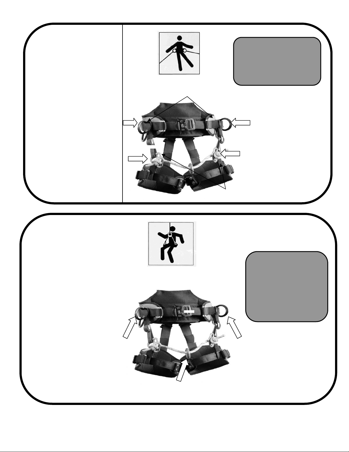
EN 358
Work positioning “D”
rings must ALWAYS
be used together
Attachment points
conforming to CE
standard EN 358
These attachment points are
designed to hold the user in
position at their work station
(work positioning) allowing them
to work with their hands free.
These attachment points shall
only be used to attach to a
suspension or work positioning
system, with maximum fall
distance of 18” (0.5m)
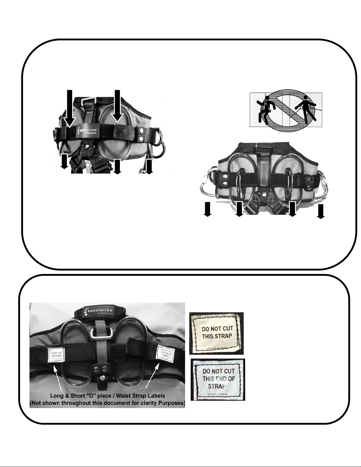
Warning
These attachment points are
not designed for fall arrest use.
It may be necessary to
supplement work positioning
or suspension systems
collectively with fall arrest
systems such as safety nets or
personal fall arrest systems
conforming to EN 363 or ANSI
Z359
EN 358
EN 358
EN 813
Sit harnesses
Only use equipment
compatible and
rated for life
support
Attachment points
conforming to CE
standard EN 813
These attachment points are
for sit harnesses that are used
in work positioning,
suspension, and rope access
systems when a ventral (low
attachment point is necessary.
Warning
These attachment points are
not designed for fall arrest use.
It may be necessary to
supplement work positioning or
suspension systems
collectively with fall arrest
systems such as safety nets or
personal fall arrest systems
conforming to EN 363 or ANSI
Z359
EN 813
EN 813
Work Positioning
attachment
oints
Suspension
attachment points