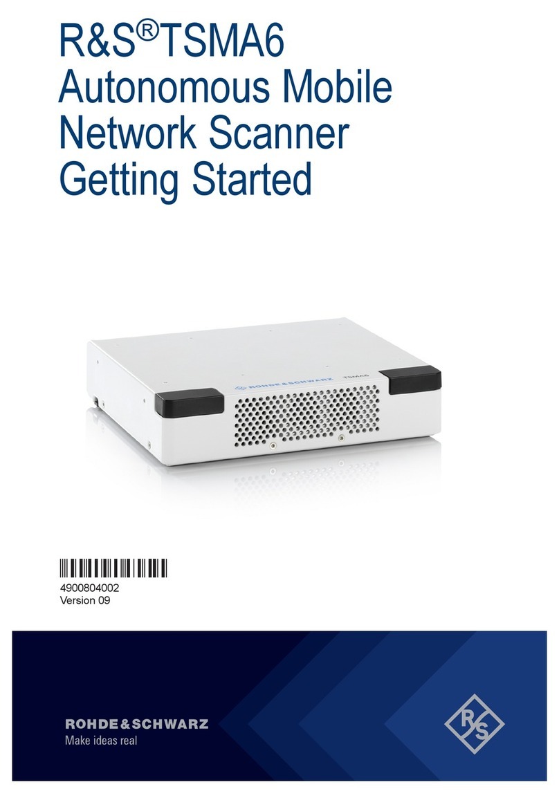
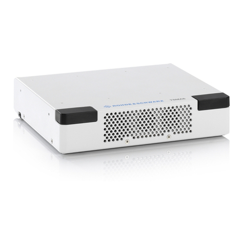
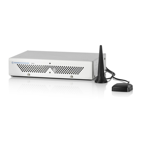
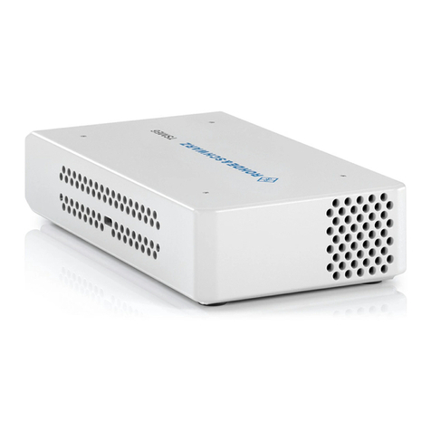
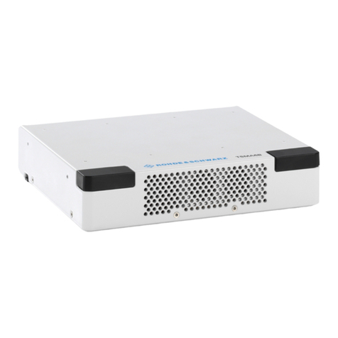
Rohde & Schwarz TSME6 User manual

R&S®TSME6
Ultra Compact Drive Test
Scanner
Getting Started
Getting Started
Version 02
4900002702
(a00K2)

This manual applies to the following R&S®TSME6 models and options:
●R&S®TSME6 (4900.0004.02)
© 2019 Rohde & Schwarz GmbH & Co. KG
Mühldorfstr. 15, 81671 München, Germany
Phone: +49 89 41 29 - 0
Fax: +49 89 41 29 12 164
Email: [email protected]
Internet: www.rohde-schwarz.com
Subject to change – Data without tolerance limits is not binding.
R&S® is a registered trademark of Rohde & Schwarz GmbH & Co. KG.
Trade names are trademarks of the owners.
4900.0027.02 | Version 02 | R&S®TSME6
Throughout this manual, products from Rohde & Schwarz are indicated without the ® symbol , e.g.
R&S®TSME6 is indicated as R&S TSME6.

Contents
R&S®TSME6
3Getting Started 4900.0027.02 ─ 02
Contents
1 Safety Information................................................................. 5
2 Documentation Overview......................................................6
2.1 Getting Started Manual.........................................................................6
2.2 User Manuals and Help........................................................................ 6
2.3 Tutorials................................................................................................. 6
2.4 Basic Safety Instructions..................................................................... 6
2.5 Brochures and Data Sheets................................................................. 7
2.6 Application Notes, Application Cards, White Papers, etc.................7
3 Key Features.......................................................................... 8
4 Preparing for Use...................................................................9
4.1 Putting into Operation.......................................................................... 9
4.2 Switching the Instrument On and Off............................................... 29
5 Instrument Tour................................................................... 31
5.1 Front Panel View................................................................................. 31
5.2 Rear Panel View.................................................................................. 32
Index..................................................................................... 36

Contents
R&S®TSME6
4Getting Started 4900.0027.02 ─ 02

Safety Information
R&S®TSME6
5Getting Started 4900.0027.02 ─ 02
1 Safety Information
The product documentation helps you to use the R&S TSME6 safely and effi-
ciently. Follow the instructions provided here and in the printed "Basic Safety
Instructions". Keep the product documentation nearby and offer it to other users.
Intended use
The R&S TSME6 is designated for the development, production and verification
of electronic components and devices in industrial, administrative, and laboratory
environments. Use the R&S TSME6 only for its designated purpose. Observe the
operating conditions and performance limits stated in the data sheet.
Where do I find safety information?
Safety information is part of the product documentation. It warns you about the
potential dangers and gives instructions how to prevent personal injuries or dam-
age caused by dangerous situations. Safety information is provided as follows:
●The printed "Basic Safety Instructions" provide safety information in many lan-
guages and are delivered with the R&S TSME6.
●Throughout the documentation, safety instructions are provided when you
need to take care during setup or operation.

Documentation Overview
R&S®TSME6
6Getting Started 4900.0027.02 ─ 02
2 Documentation Overview
This section provides an overview of the R&S TSME6 user documentation.
Unless specified otherwise, you find the documents on the R&S TSME6 product
page at:
www.rohde-schwarz.com/manual/tsme6
2.1 Getting Started Manual
Introduces the R&S TSME6 and describes how to set up and start working with
the product. Includes basic operations, typical measurement examples, and gen-
eral information, e.g. safety instructions, etc. A printed version is delivered with
the instrument.
2.2 User Manuals and Help
Contains the description of all instrument modes and functions. It also provides
information on maintenance, instrument interfaces and error messages. Includes
the contents of the getting started manual .
2.3 Tutorials
Tutorials offer guided examples and demonstrations on operating the
R&S TSME6. They are provided on the internet page of the product.
2.4 Basic Safety Instructions
Contains safety instructions, operating conditions and further important informa-
tion. The printed document is delivered with the instrument.
Basic Safety Instructions

Documentation Overview
R&S®TSME6
7Getting Started 4900.0027.02 ─ 02
2.5 Brochures and Data Sheets
The data sheet contains the technical specifications of the R&S TSME6. It also
lists the firmware applications and their order numbers, and optional accessories.
The brochure provides an overview of the instrument and deals with the specific
characteristics.
See www.rohde-schwarz.com/brochure-datasheet/tsmx
2.6 Application Notes, Application Cards, White
Papers, etc.
These documents deal with special applications or background information on
particular topics.
See www.rohde-schwarz.com/application/tsmx
Application Notes, Application Cards, White Papers, etc.

Key Features
R&S®TSME6
8Getting Started 4900.0027.02 ─ 02
3 Key Features
The R&S TSME6 sets standards in RF performance and usability. Outstanding
key features are:
●Simultaneous measurements with no limitations in 3GPP frequency bands
and technologies with SIB/L3 decoding support up to 6GHz
●More than ten technologies simultaneously in one scanner
●Future-proof for upcoming 5G related measurements
●Compact and lightweight design with customized mechanical concept for cas-
cading
●Low power consumption
●Up- and downward compatibility for maximum degree of freedom (e.g R&S
TSME)
●Easy software and hardware upgrades for new features support
For a detailed specification refer to the data sheet.

Preparing for Use
R&S®TSME6
9Getting Started 4900.0027.02 ─ 02
4 Preparing for Use
●Putting into Operation....................................................................................... 9
●Switching the Instrument On and Off.............................................................. 29
4.1 Putting into Operation
This section describes the basic steps to be taken when setting up the
R&S TSME6 for the first time.
Risk of injury due to disregarding safety information
Observe the information on appropriate operating conditions provided in the
data sheet to prevent personal injury or damage to the instrument. Read
and observe the basic safety instructions provided with the instrument, in
addition to the safety instructions in the following sections. In particular:
●Do not use an isolating transformer to connect the instrument to the AC
power supply.
●Do not open the instrument casing.
Risk of instrument damage due to inappropriate operating conditions
Specific operating conditions are required to ensure accurate measure-
ments and to avoid damage to the instrument. Observe the information on
appropriate operating conditions provided in the basic safety instructions
and the instrument's data sheet.
Putting into Operation

Preparing for Use
R&S®TSME6
10Getting Started 4900.0027.02 ─ 02
Instrument damage caused by electrostatic discharge
Electrostatic discharge (ESD) can damage the electronic components of the
instrument and the device under test (DUT). Electrostatic discharge is most
likely to occur when you connect or disconnect a DUT or test fixture to the
instrument's test ports. To prevent electrostatic discharge, use a wrist strap
and cord and connect yourself to the ground, or use a conductive floor mat
and heel strap combination.
Risk of instrument damage during operation
An unsuitable operating site or test setup can cause damage to the instru-
ment and to connected devices. Ensure the following operating conditions
before you switch on the instrument:
●The instrument is dry and shows no sign of condensation.
●The instrument is positioned as described in the following sections.
●Signal levels at the input connectors are all within the specified ranges.
EMI impact on measurement results
Electromagnetic interference (EMI) may affect the measurement results.
To suppress generated electromagnetic interference (EMI):
●Use suitable shielded cables of high quality. For example, use double-
shielded RF and LAN cables.
●Always terminate open cable ends.
●Note the EMC classification in the data sheet.
●Unpacking and Checking the Instrument.........................................................11
●Accessory List................................................................................................. 11
●Cascading R&S TSME6s................................................................................ 11
●Connecting the DC Power Supply...................................................................16
●Setting Up the LAN Connection to the Host PC..............................................18
●Connecting External Devices.......................................................................... 26
●Connecting a Kensington Lock....................................................................... 27
●Enabling Untethered Dead Reckoning ...........................................................28
Putting into Operation
Preparing for Use
R&S®TSME6
11Getting Started 4900.0027.02 ─ 02
4.1.1 Unpacking and Checking the Instrument
Check the equipment for completeness using the delivery note and the accessory
lists for the various items. Check the instrument for any damage. If there is dam-
age, immediately contact the carrier who delivered the instrument. Make sure not
to discard the box and packing material.
Packing material
Retain the original packing material. If the instrument needs to be transpor-
ted or shipped later, you can use the material to protect the control ele-
ments and connectors.
4.1.2 Accessory List
The instrument comes with the following accessories:
●Printed Getting Started manual
●LAN cable
●GPS antenna
●12 V DC power supply cable (cigarette lighter cable)
●4 connecting screws
4.1.3 Cascading R&S TSME6s
Rackmounting
The R&S TSME6 can be installed in a 19 inch rack using a rack adapter kit for
one to four R&S TSME6s (option R&S TSME6-Z2, R&S no. 4900.1030.02). The
installation instructions are part of the adapter kit.
Putting into Operation
Preparing for Use
R&S®TSME6
12Getting Started 4900.0027.02 ─ 02
Figure 4-1: Rackmounting of 2 R&S
TSME6s
Figure 4-2: Rackmounting of 2 R&S
TSME6s (reverse orientation of R&S
TSME6s)
Putting into Operation
Preparing for Use
R&S®TSME6
13Getting Started 4900.0027.02 ─ 02
Figure 4-3: Rackmounting of 4 R&S
TSME6s
Figure 4-4: Rackmounting of 4 R&S
TSME6s (reverse orientation of R&S
TSME6s)
Putting into Operation
Preparing for Use
R&S®TSME6
14Getting Started 4900.0027.02 ─ 02
Risk of instrument damage due to overheating
An insufficient airflow can cause the instrument to overheat, which may dis-
turb the operation and even cause damage. Make sure that all fan openings
are unobstructed and that the airflow perforations are unimpeded, particu-
larly when the instrument is installed in a rack or packed in a backpack. The
R&S TSME6 draws in fresh air from the front pane and warm air flows out
at its panes. Thus, if no active cooling is installed, ensure that the following
surrounding spaces to the instrument are kept clear:
●Front pane: minimum 2 cm
●Left/right panes: minimum 1 cm
Other mounting options
To connect two R&S TSME6 devices directly, perform the following steps.
1. Screw the connecting elements (R&S No. 4900.0804.00) on the top of the
R&S TSME6.
● Torque: 0.66 Nm ± 0.05 Nm
● Secure with liquid plastic
Figure 4-5: Connecting elements
1 = Connecting elements (R&S No.4900.0804.00)
2. Align the connecting elements with the holes on the bottom of a second
R&S TSME6 and press the R&S TSME6 down.
Putting into Operation
Preparing for Use
R&S®TSME6
15Getting Started 4900.0027.02 ─ 02
Figure 4-6: Aligning R&S
TSME6s
1 = 1st R&S TSME6
2 = Connecting screws
3 = 2nd R&S TSME6
4 = Holes on the bottom pane of R&S TSME6
3. Push the 1st R&S TSME6 to the front until the mechanism locks.
To disconnect the R&S TSME6 lift the release button on the pane of the upper
R&S TSME6 and slide it until the device is released.
Putting into Operation
Preparing for Use
R&S®TSME6
16Getting Started 4900.0027.02 ─ 02
Figure 4-7: Disconnect two R&S
TSME6s
1 = Release button
4.1.4 Connecting the DC Power Supply
The DC power supply connector is on the rear panel of the unit. Voltages from
10 V to 28 V are supported. There is no need to set the used voltage manually.
Possible power cable connections
The R&S TSME6 can work with the following DC power supplies:
●Cigarette lighter power supply (for example in a vehicle) using the supplied
DC power cable
●Optional AC power supply and power cable R&S TSME6-Z1 (see )
●Proprietary power supply with an adapted power cable
Using the supplied cigarette lighter power supply cable
► To use the power supply from a cigarette lighter, connect the supplied power
cable from the R&S TSME6 to the cigarette lighter.
Putting into Operation

Preparing for Use
R&S®TSME6
17Getting Started 4900.0027.02 ─ 02
Connecting a proprietary power supply
► To use a proprietary DC supply with the R&S TSME6 power cable, demount
the cigarette lighter adapter from the supplied power cable and connect the
open ends of the cable to the proprietary power supply. Be sure to respect the
correct polarity (see Figure 4-8).
Figure 4-8: Supplied power cable with cigarette lighter adapter
Putting into Operation
Preparing for Use
R&S®TSME6
18Getting Started 4900.0027.02 ─ 02
Danger of shock!
To avoid a shock hazard and instrument damage, note the following:
●After moisture condensation, allow the instrument to dry before switch-
ing on.
●The instrument is still power-supplied while it is in standby mode, that is,
with the power button switched off, but still connected with the DC
power supply.
●After connecting the power supply, the instrument is immediately under
power.
●The supplied DC connector is intended for disconnection.
●If any DC supply other than R&S TSME6-Z1 is used:
– The DC supply must be in accordance with IEC / EN / UL / CSA
60950-1 or IEC / EN / UL / CSA EN EN61010-1.
– Use only Safety Extra Low Voltage (SELV) power supplies
– Observe the DC input range of 10 V to 27 V with maximum of 1.8 A
(inrush current)
– The 12 V vehicle cigarette lighter socket must be fused
4.1.5 Setting Up the LAN Connection to the Host PC
To control and run measurements with the R&S TSME6, a host PC or notebook
with LAN interface is required.
The R&S TSME6 is equipped with a network interface and can be connected to
an Ethernet LAN (local area network). The interface can be used to connect the
R&S TSME6 to a host PC.
How to connect multiple R&S TSME6s to a single host PC (for example for
LTE MIMO setups) is described in the R&S TSME6 User Manual.
The following scenarios are possible.
●Connection between PC and R&S TSME6(s) using static IP addresses.
Putting into Operation
Preparing for Use
R&S®TSME6
19Getting Started 4900.0027.02 ─ 02
●Connection between PC and R&S TSME6(s) using dynamical generated IP
addresses (Auto-IP).
Operating Modes
●"Full auto-IP" operating mode
IP addresses are automatically generated on PC and R&S TSME6(s) if the
following conditions are met:
– PC network interface is configured to obtain an IP address automatically
– IP address stored in R&S TSME6(s) is not in range 169.254.0.1 –
169.254.255.254 (inclusive).
Note: This is the IP address set by the R&S TSME Device Manager.
●"Partial auto-IP" operating mode
IP address is automatically generated on PC and a static IP address is used
on R&S TSME6 if the following conditions are met:
– PC network interface is configured to obtain an IP address automatically
– IP address stored in R&S TSME6 is in range 169.254.0.1 –
169.254.255.254 (inclusive).
Note: This is the IP address set by the R&S TSME Device Manager.
●"Static IP" operating mode
IP address is manually set on PC and a static IP used on R&S TSME6 if the
following conditions are met:
– PC LAN interface is configured to use a user defined IP address, not in
range 169.254.0.1 – 169.254.255.254 (inclusive).
Recommendations/Limitations of Operating Modes
●"Full auto-IP" operating mode
– Only 1 PC and 1 or more R&S TSME6 devices per LAN interface, either
connected directly or via a L2 switch. (This operating mode shall not be
used when more than 1 PC is physically connected to the same subnet-
work, e.g. via the switch.)
– PC’s LAN interface shall not receive an IP from a DHCP server. (The IP
address generated for PC shall be matching following pattern:
169.254.X.Y.)
– All R&S TSME6 devices on the same LAN interface shall be configured
with stored IP addresses not in the range 169.254.1.0 – 169.254.254.255
(inclusive) to prevent conflicts.
Putting into Operation

Preparing for Use
R&S®TSME6
20Getting Started 4900.0027.02 ─ 02
Note: R&S TSME6 devices with stored IP addresses in ranges
169.254.0.1 – 169.254.0.255 (inclusive) or 169.254.255.0 –
169.254.255.254 (inclusive) are effectively operating in "partial auto-IP"
operating mode.
– Depending on software accessing the R&S TSME6 devices, it may be
mandatory to configure the stored IP addresses in all R&S TSME6 devices
to be unique.
Example: R&S TSME Device Manager does not have this requirement,
R&S ROMES / R&S Nestor may have such requirements depending on
the use made internally of the stored IP address as unique identifier.
●"Partial auto-IP" operating mode
This mode shall only be used for specific cases, "full auto-IP" or "static IP"
operating modes shall be preferred.
– 1 or more PCs and 1 or more R&S TSME6 devices per LAN interface,
either connected directly or via a L2 switch
– Each of the PC’s LAN interface physically connected to the sub network
shall not receive an IP from a DHCP server. (The IP address generated for
PC shall be matching following pattern: 169.254.X.Y.)
– All R&S TSME6 devices on the same LAN interface shall be configured
with stored IP addresses in the ranges 169.254.0.1 – 169.254.0.255 (inclu-
sive) or 169.254.255.0 – 169.254.255.254 (inclusive), and use unique IP
addresses.
These ranges are important to prevent conflicts with IP addresses dynami-
cally generated for the PC LAN interfaces.
Note: If a R&S TSME6 is shared with 2 or more PCs, and its stored IP
address is not in the defined range above, this may lead in rare cases to IP
conflicts. It is therefore recommende to respect this rule.
●"Static IP" operating mode
– 1 or more PCs and 1 or more R&S TSME6(s), either connected directly or
via a L2 switch.
– Other network devices are permitted, as long as all IP addresses used are
unique.
This section describes how to configure the LAN interface for a single
R&S TSME6. It includes the following topics:
●Configuring the LAN Interface On the Host PC...............................................21
●Firewall Configuration..................................................................................... 24
●Connecting the R&S TSME6 to the Host PC.................................................. 25
Putting into Operation
Other manuals for TSME6
2
Table of contents
Other Rohde & Schwarz Scanner manuals

Rohde & Schwarz
Rohde & Schwarz TSMA User manual

Rohde & Schwarz
Rohde & Schwarz TSMA6B User manual

Rohde & Schwarz
Rohde & Schwarz TSMA6 Series User manual

Rohde & Schwarz
Rohde & Schwarz R&S TSMA6 User manual

Rohde & Schwarz
Rohde & Schwarz TSME User manual

Rohde & Schwarz
Rohde & Schwarz TSMA6B User manual

Rohde & Schwarz
Rohde & Schwarz TSMA6B User manual

Rohde & Schwarz
Rohde & Schwarz TSME6 User manual

Rohde & Schwarz
Rohde & Schwarz TSME6 User manual

Rohde & Schwarz
Rohde & Schwarz TSMA6B User manual