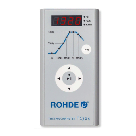
Rohde TC 304 User manual

Bedienungsanleitung
Instruction Manual
Notice d’utilisation
Istruzioni per l’uso
Manual de instrucciones
Betjeningsvejledning TC 304

DEUTSCH
2 3
Inhaltsverzeichnis
Einleitung . . . . . . . . . . . . . . . . . . . . . . . . . . . . . . . . . . . . . . . . . . . . . . . . . . . . . .3
Die Bedienelemente . . . . . . . . . . . . . . . . . . . . . . . . . . . . . . . . . . . . . . . . . . . . . .3
Montage der Regelanlage TC 304 . . . . . . . . . . . . . . . . . . . . . . . . . . . . . . . . . . .4
Kurzanleitung . . . . . . . . . . . . . . . . . . . . . . . . . . . . . . . . . . . . . . . . . . . . . . . . . . .5
Aufrufen eines Programms . . . . . . . . . . . . . . . . . . . . . . . . . . . . . . . . . . . . . . . . .6
Starten des Brandes . . . . . . . . . . . . . . . . . . . . . . . . . . . . . . . . . . . . . . . . . . . . .6
Brennkurve/Programm eingeben/ändern . . . . . . . . . . . . . . . . . . . . . . . . . . . . .7
Anhang A: Fehler- und Ereignismeldungen . . . . . . . . . . . . . . . . . . . . . . . . . . . . .9
Anhang B: Elektrische Anschlüsse . . . . . . . . . . . . . . . . . . . . . . . . . . . . . . . . . .12
Einleitung
Mit der Regelanlage TC 304 haben Sie sich für einen hochwertigen Regler ent-
schieden. Die Reglerserie ist durch die Verwendung neuester Technologien führend
in dieser Klasse.
Nach Durchlesen der vorliegenden Anleitung sind Sie mit allen wichtigen Funktionen
der TC 304 vertraut. Beachten Sie zusätzlich die Sicherheitshinweise des Ofen-
herstellers.
Achten Sie darauf, dass die Steuerung in ausreichendem Abstand vom Ofen mon-
tiert und außerdem keiner direkten Hitze vom Ofen durch Abluft oder Strahlung
ausgesetzt wird.
Die Bedienelemente
1 Istwert-Anzeige
2 Anzeige der Einheiten/Werte
3 Programmabschnitt Vorlaufzeit t0
4 Programmabschnitt 1. Aufheizgeschwindigkeit Rmp1
5 Programmabschnitt 1. Umschaltpunkt Tmp1
6 Programmabschnitt 2. Aufheizgeschwindigkeit Rmp2
7 Programmabschnitt Endtemperatur Tmp2
8 Programmabschnitt Haltezeit der Endtemperatur t2
9 Programmabschnitt Abkühlgeschwindigkeit Rmp3
10 Anzeige für Programmende
11 Taste zur Auswahl der Programme 1– 5
12 Taste zum Zurückspringen
13 Taste für Programm „Start / Stopp“
14 Aktuellen Wert verändern +
15 Taste zum Vorspringen
16 Aktuellen Wert verändern –
17 Netzschalter ein/aus
1
7
6
5
4
3
12
13
2
89
10
11
14
15
16
17

DEUTSCH
4 5
Kurzanleitung
Programm starten
1. Netzschalter einschalten, der Netzschalter befindet sich
an der Gehäuseunterseite, Anzeige der Ist-Temperatur im
Display.
2. Aufrufen der Programme durch ein- oder mehrmaliges
Drücken der prog-Taste. Im Display erscheint erst die
Programmnummer, danach erscheint die Endtemperatur.
3. Starten oder Stoppen des ausgewählten Programms mit
der Taste „Start/Stopp“.
Hinweis: Überprüfen Sie vor jedem Programmstart die ein-
gestellten Programmwerte.
Programm ändern
1.–2. Siehe oben.
3. Programmabschnitt mit den Pfeiltasten oder aus-
wählen.
4. Werte des ausgewählten Programmabschnitts mit den
Pfeiltasten
oder
ändern. Die Werte werden automatisch
gespeichert.
5. Starten oder Stoppen des ausgewählten Programms mit
der Taste „Start/Stopp“.
Programme speichern
Die TC 304 speichert alle veränderbaren Werte der Brenn-
kurve automatisch ab.
Montage der Regelanlage TC 304
Wandmontage
Wählen Sie für die Montage einen sicheren und gut bedienbaren Platz neben dem
Ofen an der Wand.
Schrauben Sie zuerst die beiden mitgelieferten Rändelschrauben in die auf der
Rückseite des Reglers vorgesehenen Löcher. Damit wird der Regler später in der
Halterung fixiert.
Montieren Sie jetzt mit Hilfe der drei Dübel und der
drei Schrauben die Befestigungsplatte der Regelanlage
TC 304 so, dass ein Befestigungsloch nach oben
zeigt und zwei Löcher nach unten zeigen.
Die Klarsichtschutzfolie muss in jedem Fall zu Ihnen
gerichtet sein!
Jetzt kann der Regler von oben in die jeweilige Hal-
terung eingehängt werden. Unter Umständen müssen
die Rändelschrauben am Regler ein wenig gelockert
werden.
Montage auf der KE-Reglerplatte
Platzieren Sie die mitgelieferte Kammerofen-Reglerplatte so, dass Sie die beiliegende
Sterngriffschraube in die dafür vorgesehene Montagestelle eindrehen können. Ist
die Reglerplatte fest angeschraubt, kann mit der Montage des Reglers auf der
Reglerplatte begonnen werden.
Montieren Sie jetzt mit Hilfe der drei Schrauben, Muttern und Beilagscheiben die
Befestigungsplatte der Regelanlage TC 304 so, dass ein Befestigungsloch nach
oben zeigt und zwei Löcher nach unten zeigen.
Die Klarsichtschutzfolie muss in jedem Fall zu Ihnen gerichtet sein!
Schrauben Sie zuerst die beiden mitgelieferten Rändelschrauben in die auf der
Rückseite des Reglers vorgesehenen Löcher.
Jetzt kann die Regelanlage von oben in die jeweilige Halterung eingehängt werden.
Unter Umständen müssen die Rändelschrauben am Regler ein wenig gelockert
werden.

DEUTSCH
6 7
Brennkurve/Programm eingeben/ändern
Die Regelanlage TC 304 erlaubt eine präzise und reproduzierbare Steuerung Ihres
Brennofens.
Auf der Vorderseite des Reglers finden Sie eine schematische Darstellung einer
Brennkurve. Sie setzt sich aus verschiedenen Programmabschnitten (sogenannten
Segmenten) zusammen.
Jeder Programmabschnitt ist mit einer
Abkürzung bezeichnet (t0, Rmp1,
Tmp1, Rmp2, Tmp2, t2 und Rmp3)
und hat eine entsprechende Status-
LED. Mit den Pfeiltasten
und
können Sie zwischen den verschie-
denen Programmabschnitten wech-
seln. Die Status-LED zeigt Ihnen
dabei durch Blinken an, in welchem
Programmabschnitt Sie sich befinden.
Wählen Sie zuerst den Programmplatz aus, auf dem Sie ein neues Programm
speichern bzw. ein vorhandenes Programm ändern möchten.
Drücken Sie dazu wiederholt die prog-Taste, bis der gewünschte Speicherplatz
(1 bis 5) im Display erscheint. Die Anzeige wechselt nach einigen Sekunden und
zeigt nun die entsprechende Endtemperatur (Tmp2) des gewählten Programms an.
Dazu blinkt die entsprechende LED im Programmabschnitt „Tmp2“.
Vorlaufzeit bzw. Programmstartverzögerung: t0
Die Regelung verzögert den Start des Brennvorganges um die eingestellte Zeit.
Drücken Sie wiederholt die Taste oder , bis die Status LED im Programm-
abschnitt Vorlaufzeit „t0“ blinkt. Im Display wird der aktuell hinterlegte Wert
angezeigt. Mit den Tasten oder können Sie einen Wert zwischen 0.00
(kein Vorlauf) und 9.59 (Stunden.Minuten) eingeben.
Aufheizgeschwindigkeit bis 1. Umschaltpunkt: Rmp1
Der Ofen wird mit der angegebenen Geschwindigkeit aufgeheizt. Die Eingabe erfolgt
standardmäßig in Grad Celsius pro Stunde.
Drücken Sie wiederholt die Taste oder , bis die Status LED im Programm-
abschnitt 1. Aufheizrampe „Rmp1“ blinkt. Im Display wird der aktuell
hinterlegte Wert angezeigt. Mit den Tasten oder können Sie einen Wert
zwischen 1 und 999°C/h, bzw. SKIP (Vollastheizen) eingeben.
Aufrufen eines Programms
Die TC 304 kann fünf Brennkurven (sogenannte Programme) abspeichern. Werk-
seitig sind die Programme 1–4 mit Standardbrennkurven belegt, die verändert
werden können (siehe Tabelle unten).
Die voreingestellten Programme sind Empfehlungen und sollten entsprechend der
von Ihnen verwendeten Materialien angepasst werden:
Prog. Bezeichnung t0 Rmp1 Tmp1 Rmp2 Tmp2 t2 Rmp3
Nr. (h.min) (°C/h) (°C) (°C/h) (°C) (h.min) (°C/h)
01* Einbrand 1050°C 0 100 1050 SKIP 1050 1.30 SKIP
02 Schrühbrand 950°C 0 60 600 100 950 0.00 SKIP
03 Irdenware 1050°C 0 150 900 100 1050 0.30 SKIP
04 Steinzeug 1250°C 0 150 900 60 1250 0.05 SKIP
Im folgenden Beispiel rufen wir die Brennkurve Programm Nr. 04 auf und starten
den Brand. Nach dem Einschalten der TC 304 zeigt das Display die Raumtempe-
ratur an. Drücken Sie nun wiederholt die prog-Taste, bis im Display „P4“ angezeigt
wird. Die Anzeige wechselt nach einigen Sekunden und zeigt nun die entsprechende
Endtemperatur des gewählten Programms an.
Starten des Brandes
Um das Programm zu starten, betätigen Sie die Taste „Start/Stopp“. Das Display
zeigt nun die die aktuelle Ofentemperatur an und in der Taste „Start/Stopp“ leuchtet
die grüne LED.
* Das voreingestellte Programm Nr. 01 „Einbrand“ empfehlen wir für das erste Einbrennen Ihres Ofens,
neuer Heizelemente (Oxidationsbrand) und neuen Besatzmaterials (Stützen und Platten). Beim Einbrand
sollten die Zu- und Abluftöffnungen des Ofens geöffnet sein. Beachten Sie dazu auch die Bedienungs-
anleitung Ihres Brennofens.
Hinweis: Falls in einer geregelten Rampe der Ofen dem geforderten Anstieg
nicht folgen kann, pausiert der Regler auf der Temperatur, bis der Brennofen die
geforderte Soll-Temperatur wieder erreicht hat (die LED über der Taste „Start/Stopp“
leuchtet in dieser Zeit orange). Ist die Temperatur erreicht, wird die Rampe wieder
fortgesetzt. Dieser Vorgang kann sich wiederholen, somit verlängert sich die
tatsächliche Dauer der Rampe.

DEUTSCH
8 9
Drücken Sie wiederholt die Taste oder , bis die Status LED im Programm-
abschnitt Abkühlzeit oder Programmende „Rmp3“ blinkt. Im Display wird
der aktuell hinterlegte Wert angezeigt. Mit den Tasten
oder
können Sie
einen Wert zwischen 1 und 999°C/h, bzw. SKIP (ungeregeltes Abkühlen)
eingeben.
Programme speichern
Die TC 304 speichert alle veränderbaren Werte der Brennkurve automatisch ab.
Wird von der Regelanlage über einen Zeitraum von 30 Sekunden keine Eingabe
registriert, wird die Bearbeitung des Programms beendet und im Display wird wieder
die Raumtemperatur angezeigt.
Alternativ können Sie das ausgewählte Programm direkt mit der Taste „Start/Stopp“
starten oder die Regelanlage mit dem Netzschalter ausschalten.
Die veränderten Werte werden dabei in allen Fällen automatisch gespeichert.
Anhang A: Fehler- und Ereignismeldungen der TC 304
Fehler- und Ereignisspeicher
Besondere Ereignisse (Netzausfall, Fühlerbruch, Ofenproblem etc.) werden vom
Regler erkannt und entsprechend abgehandelt.
Die Ereigniscodes sind unterteilt in:
E-CODE A = Betriebs- bzw. Regelprobleme
E-CODE B = Stromausfallprobleme
E-CODE C = interne Probleme
E-CODE D = Hardwareprobleme
Nachfolgend sind die möglichen Ereignismeldungen aufgelistet und deren Bedeutung
erklärt.
Temperatur für 1. Umschaltpunkt: Tmp1
Der Ofen heizt mit der zuvor eingegebenen Aufheizgeschwindigkeit (Rmp1) bis zu
der am 1. Umschaltpunkt eingegebenen Temperatur. Die Eingabe der Temperatur
erfolgt standardmäßig in Grad Celsius.
Drücken Sie wiederholt die Taste oder , bis die Status LED im Programm-
abschnitt 1. Umschaltpunkt „Tmp1“ blinkt. Im Display wird der aktuell
hinterlegte Wert angezeigt. Mit den Tasten oder können Sie einen Wert
zwischen 20 und 1320°C eingeben.
Aufheizen auf Endtemperatur: Rmp2
Der Ofen heizt mit der angegebenen Geschwindigkeit auf Endtemperatur. Die
Eingabe erfolgt standardmäßig in Grad Celsius pro Stunde.
Drücken Sie wiederholt die Taste oder , bis die Status LED im Programm-
abschnitt 2. Aufheizrampe „Rmp2“ blinkt. Im Display wird der aktuell
hinterlegte Wert angezeigt. Mit den Tasten oder können Sie einen Wert
zwischen 1 und 999°C/h, bzw. SKIP (Vollastheizen) eingeben.
Temperatur für Endtemperatur: Tmp2
Der Ofen heizt mit der oben eingegebenen Geschwindigkeit bis zur Haltetemperatur.
Die Eingabe erfolgt standardmäßig in Grad Celsius.
Drücken Sie wiederholt die Taste oder , bis die Status LED im Programm-
abschnitt Endtemperatur „Tmp2“ blinkt. Im Display wird der aktuell hinter-
legte Wert angezeigt. Mit den Tasten
oder
können Sie einen Wert
zwischen 20 und 1320°C eingeben.
Haltezeit auf Endtemperatur: t2
Der Ofen verweilt für die Dauer der eingestellten Zeit auf der Endtemperatur. Eine
Haltezeit sorgt für gleichmäßiges Durchheizen des Brenngutes im Ofen.
Drücken Sie wiederholt die Taste oder , bis die Status LED im Programm-
abschnitt Haltezeit bei Endtemperatur „t2“ blinkt. Im Display wird der aktuell
hinterlegte Wert angezeigt. Mit den Tasten oder können Sie einen Wert
zwischen 0.00 und 9.59 (Stunden.Minuten) eingeben.
Abkühlen bzw. Programmende: Rmp3
Nach Beenden der Haltezeit kühlt der Ofen ab, geregelt (z. B. 200°C/h) oder
ungeregelt (= SKIP). Bei 150°C beendet der Regler die Temperaturkontrolle und
zeigt daraufhin mit „End“ in der Anzeige das Ende des Brandes an.
E A4

DEUTSCH
10 11
Ereignis E A9 · SKIP-Rampe wurde zwangsweise beendet
Falls der Regler in einer ungeregelten Rampe vergeblich versucht hat, im Ofen die
Endtemperatur zu erreichen, wird zwangsweise in das nächste Segment geschaltet.
Zur Information des Benutzers wird dann für eine Minute diese Meldung angezeigt.
Ereignis E B3 · Brennvorgang nach Netzausfall unterbrochen
Nach der Wiederkehr der Netzspannung wurde der Brand abgebrochen, da z.B.
die Ofentemperatur in der Zwischenzeit zu weit gefallen war. Eine eventuell ange-
zeigte Kommastelle (z. B. B3.4 = Temperatur zu weit gefallen) gibt weitere Auskunft
über die Ursache. Wenn diese Meldung sofort nach dem Einschalten des Reglers
erscheint, brauchen Sie diese nicht zu beachten. Sie bedeutet lediglich, dass der
Regler beim letzten Brand noch während des Programmlaufes ausgeschaltet wurde.
Beginnen Sie einfach mit der Programmeingabe.
Ereignis E B2
Der Brennvorgang wird nach einem Netzausfall fortgesetzt, wenn die Temperatur
um nicht mehr als 50°C abgefallen ist.
Ereignis E B4
Die Umgebungstemperatur des Reglers hat 55°C überschritten. Belüftung des
Raumes überprüfen, ggf. befindet sich der Regler zu nahe am Brennofen.
Anzeige OVR
Keine Verbindung zum Thermoelement vorhanden. Das Thermoelement ist defekt,
nicht angeschlossen, die Messleitung unterbrochen oder die Steckerkontakte sind
verschmutzt bzw. defekt („overrun“ = Messbereichsüberlauf).
Anzeige UDR
Das Thermoelement ist falsch verpolt, oder ein falscher Thermoelement-Typ wurde
angeschlossen („underrun“).
Ereignis E A1 · Fehler am Messeingang
Regelung abgeschaltet wegen Fehler am Messeingang (z. B. Messbereichsüberlauf).
Erst bei erneutem Start eines Programmes wird der Fehler zurückgesetzt.
Mögliche Ursachen:
• Thermoelement oder Zuleitung unterbrochen
• Maximaltemperatur des Reglers überschritten
• Thermoelement falsch gepolt angeschlossen (Temperaturanzeige „UNDER“)
Ereignis E A3 · Sicherheitskreis wurde aktiv
Bei Überschreitung der maximalen Programmtemperatur um mehr als 20°C wird
der Sicherheitskreis aktiv und schaltet den Ofen ab. Hiermit wird der Ofen gegen
Überbrennen geschützt.
Mögliche Ursachen für Übertemperatur:
• Ofenschütz im „EIN“-Zustand hängengeblieben
• Kontakt im Ofenschütz dauerhaft geschlossen
Ereignis E A4 · Temperaturanstieg trotz Volllast-Heizen zu gering
Diese Fehlermeldung weist eindeutig auf ein Problem am Ofen hin.
Mögliche Ursachen:
• Netzsicherung /-phase defekt, Heizelement defekt
• Heizelemente überaltert (bei hohen Temperaturen)
• Thermoelement bzw. Zuleitung kurzgeschlossen
• Schütz defekt (tritt oft erst während des Brandes auf)
Ereignis E A5 · Ofen folgt nicht programmiertem Anstieg
Anders als Ereignis A4 kann auch ein zu hoch eingegebener Temperaturanstieg,
dem der Ofen nicht folgen kann, die Ursache sein. Meldung ist nur aktiv, wenn
entsprechend in der Konfiguration freigegeben.
Ereignis E A8 · Anstieg wurde automatisch fortgesetzt
Falls der Ofen dem Temperaturanstieg nicht folgen kann, wird die Rampe angehalten.
Wenn der Regler – nach erfolglosem Ablauf der Wartezeit – das Programm fortsetzt,
wird diese Meldung für eine Minute angezeigt.

12
Anhang B: Elektrische Anschlüsse
Steckerbelegung Steckerbelegung Steckerbelegung
HAN7D a HAN15D a CPC14 a
Anschluss Funktion HAN7D a HAN15D a CPC14 a
a Zusätzlicher Schaltausgang 7 C3 12
b Schaltausgang Schütz (Phase) 6 A3 14
c Schaltausgang Schütz (Null) 1 B3 13
d Schutzleiter (muss angeschlossen werden!) Endklemme 11
e Stromversorgung Phase 5 A1 8
f Stromversorgung Null 2 B1 9
g Thermoelement + 3 B5 1
h Thermoelement – (PtRhPt) 4 C5 2
n Thermoelement – (NiCrNi) 4 A5 3
Änderungen, die dem technischen Fortschritt dienen, bleiben vorbehalten.
Bedienungsanleitung TC 304 V 1.2 · ©2019 HELMUT ROHDE GMBH · DEUTSCHLAND
6
5
4
1
2
3
7
15
4
3
2
a
c
b
3
1
74
11
8
1412
Instruction Manual TC 304

2 32 3
ENGLISH
Table of Contents
Introduction . . . . . . . . . . . . . . . . . . . . . . . . . . . . . . . . . . . . . . . . . . . . . . . . . . . .3
Operating Elements . . . . . . . . . . . . . . . . . . . . . . . . . . . . . . . . . . . . . . . . . . . . . .3
Mounting the TC 304 Control Unit . . . . . . . . . . . . . . . . . . . . . . . . . . . . . . . . . . .4
Quick Start Guide. . . . . . . . . . . . . . . . . . . . . . . . . . . . . . . . . . . . . . . . . . . . . . . .5
Calling Up a Program . . . . . . . . . . . . . . . . . . . . . . . . . . . . . . . . . . . . . . . . . . . . .6
Starting a Firing . . . . . . . . . . . . . . . . . . . . . . . . . . . . . . . . . . . . . . . . . . . . . . . . .6
Entering/Changing a Firing Curve/Program . . . . . . . . . . . . . . . . . . . . . . . . . . . .7
Appendix A: Error and Event Messages . . . . . . . . . . . . . . . . . . . . . . . . . . . . . . .9
Appendix B: Electrical Connections . . . . . . . . . . . . . . . . . . . . . . . . . . . . . . . . .12
Introduction
You have chosen a TC 304 control unit, a high-quality product. This controller series
incorporates the latest technological features and is the leader in its class.
After reading this manual you will be familiar with the functionality of the TC 304
controller. Please make sure that you fully understand the kiln manufacturer’s safety
instructions.
Make sure that the controller is mounted at a safe distance from the kiln and is not
exposed to direct heat from exhaust air or radiation from the kiln.
Operating Elements
1 Actual value display
2 Units/values indicator
3 t0 program delay section
4 Rmp1 1st heating rate program section
5 Tmp1 1st switching point program section
6 Rmp2 2nd heating rate program section
7 Tmp2 end temperature program section
8 t2 dwell time at end temperature program section
9 Rmp3 cooling rate program section
10 End of program indicator
11 Key to select programs 1-5
12 Back key
13 “Start/Stop” program key
14 Change current value +
15 Advance key
16 Change current value –
17 Power on/off
1
7
6
5
4
3
12
13
2
89
10
11
14
15
16
17

4 54 5
ENGLISH
Quick Start Guide
Starting a program
1. Power on, the mains switch is located on the bottom of
the housing, the actual temperature is shown on the display.
2. Push the prog key once or several times to call a program.
First, the program number appears on the display, then the
end temperature is indicated.
3. Start or stop the selected program using the “Start/Stop”
key.
Note: check the set program values before each program
start.
Changing a program
1.–2. See above
3. Use the or key to select program sections.
4. Change selected program section values using the or
key. The values are saved automatically.
5. Start or stop the selected program using the “Start/Stop”
key.
Saving a program
The TC 304 automatically saves all the variable values of
the firing curve.
Mounting the TC 304 Control Unit
Mounting the control unit on the wall
Choose a safe and easily accessible position on a wall next to the kiln to mount the
control unit.
First screw the two knurled screws into the holes indicated on the back of the
controller. They will be used later to fasten the controller in the fixing device.
Mount the holding panel of the TC 304 control unit
using the three dowels and three screws, with one
fixing hole pointing upwards and the other two poin-
ting downwards.
Make sure that the transparent protective foil is
correctly aligned!
Now the controller can be plugged into the fixing
device from above. You might have to loosen the
knurled screws on the controller.
Mounting the control unit on the KE controller panel
Place the frontloader controller panel in a position that will allow the star-shaped
knob to be turned until it locks into the position indicated. When the panel is fixed,
you can start mounting the controller on the panel.
Mount the holding bar of the TC 304 control unit using the three screws, nuts and
washers, with one fixing hole pointing upwards and the other two pointing down-
wards.
Make sure that the transparent protective foil is correctly aligned!
First screw the two knurled screws into the holes indicated on the back of the
controller.
Now the controller can be plugged into the fixing device from above. You might
have to loosen the knurled screws on the controller.

6 76 7
ENGLISH
Entering/Changing a Firing Curve/Program
The TC 304 control unit allows precise, reproducible control of your kiln.
You will find a schematic firing curve on the front of the controller. It comprises
different program sections i.e. segments. Each program section is marked with an
abbreviation (t0, Rmp1, Tmp1, Rmp2, Tmp2, t2 and Rmp3) and has a respective
LED indicator.
Use the
and
arrow key to change
between the different program sec-
tions. A flashing LED indicator shows
the program section you have entered.
First decide the location where you
want to save a new program or change
an existing program.
Press the prog key until the required
storage location (1 to 5) appears on
the display. The display changes after a few seconds showing the respective end
temperature (Tmp2) of the selected program. The respective LED flashes in program
section “Tmp2”.
Program delay or program start delay: t0
The controller delays the start of the firing process for the time set.
Push the or key until the “t0” LED indicator in the program delay section
flashes. The display shows the value that has been stored. Use the or
key to enter a value between 0.00 (no delay) and 9.59 (hours.minutes).
Heating rate to 1st switching point: Rmp1
The kiln heats up at the rate set. By default, the rate is entered in degrees Celsius
per hour.
Push the
or
key until the “Rmp1” LED indicator in the 1st heating ramp
program section flashes. The display shows the value that has been stored.
Use the or key to enter a value between 1 and 999°C/h or SKIP (heating
at full power).
Calling Up a Program
The TC 304 can save up to 5 firing curves i.e. programs. Program numbers 1– 4
are factory-set with standard firing curves and can be modified (see table below).
The pre-set programs are only optional settings and can be adapted according to
the materials that you use.
Prog. Description t0 Rmp1 Tmp1 Rmp2 Tmp2 t2 Rmp3
Nr. (h.min) (°C/h) (°C) (°C/h) (°C) (h.min) (°C/h)
01* Initial firing 1050°C 0 100 1050 SKIP 1050 1.30 SKIP
02 Bisque 950°C 0 60 600 100 950 0.00 SKIP
03 Earthenware 1050°C 0 150 900 100 1050 0.30 SKIP
04 Stoneware 1250°C 0 150 900 60 1250 0.05 SKIP
In the following example we will call up program No. 04 to start the firing. After
turning on the TC 304, the display indicates the room temperature. Press the prog
key until the display shows program “P4”. The display changes after a few seconds
and shows the respective end temperature of the selected program.
Starting a Firing
Push the “Start/Stop” key to start the program. The display shows the actual kiln
temperature and the green LED on the “Start/Stop” key flashes.
* We recommend that you use preset program No. 01 “Initial firing” for the initial firing of your kiln, new
heating elements (oxidation firing) and new furniture material (stilts and batts). Open the air supply and
exhaust air openings during initial firing. Please consult the kiln instruction manual.
Note: If the kiln cannot follow the required temperature increase programmed
in a controlled ramp up, the controller dwells at the temperature until the kiln
reaches the required setpoint temperature again (the LED above the “Start/Stop”
key flashes orange). As soon as the kiln has reached this temperature, the ramp
up continues. As this process may occur repeatedly, the ramp up can actually
take longer.

8 98 9
ENGLISH
Use the
or
key to enter a value between 1 and 999°C/h or SKIP (un-
controlled cooling).
Saving a program
The TC 304 automatically saves all the variable values of the firing curve.
The control unit stops the processing of the program if no values have been entered
for 30 seconds. The display indicates the room temperature.
As an alternative, press the “Start/Stop” key to start the desired program imme-
diately or use the mains switch to turn the control unit off.
Values that have been changed are saved automatically.
Appendix A: TC 304 Error and Event Messages
Error and event messages
The controller indicates particular events such as power failure, sensor malfunctions
or kiln errors and processes them accordingly.
The event codes are:
E-CODE A = Operational and controller errors
E-CODE B = Errors resulting from power failure
E-CODE C = Internal errors
E-CODE D = Hardware errors
The list below shows possible event messages and their meaning.
Temperature for 1st switching point: Tmp1
The kiln heats up at the previously set heating rate (Rmp1) until reaching the tem-
perature set for the 1st switching point. By default, the temperature is entered in
degrees Celsius per hour.
Push the or key until the “Tmp1” LED indicator in the 1st dwell tem-
perature program section flashes. The display shows the value that has
been stored. Use the or key to enter a value between 20 and 1320°C.
Heating to end temperature: Rmp2
The kiln heats up at the rate set. By default, the rate is entered in degrees Celsius
per hour.
Push the
or
key until the “Rmp2” LED indicator in the 2nd heating ramp
program section flashes. The display shows the value that has been stored.
Use the
or
key to enter a value between 1 and 999°C/h or SKIP (heating
at full power).
Temperature for end temperature: Tmp2
The kiln heats up at the rate set until reaching the first dwell temperature. By default,
the rate is entered in degrees Celsius per hour.
Push the or key until the “Tmp2” LED indicator in the end temperature
program section flashes. The display shows the value that has been stored.
Use the or key to enter a value between 20 and 1320°C.
Dwell time at end temperature: t2
The kiln holds the end temperature for the time set. The dwell time ensures an even
heating of the fired products inside the kiln
Push the
or
key until the “t2” LED indicator in the dwell time at end
temperature program section flashes. The display shows the value that has
been stored. Use the or key to enter a value between 0.00 and 9.59
(hours.minutes).
Cooling or end of program: Rmp3
At the end of the dwell time, the kiln cools down either controlled (e.g. 200°C/h) or
uncontrolled (= SKIP). At 150°C, the controller stops the temperature control and
the display shows “End” to indicate the end of firing.
Push the or key until the “Rmp3” LED indicator in the cooling or end
of program section flashes. The display shows the value that has been
stored.
E A4

10 1110 11
ENGLISH
Event E A9 · SKIP ramp interrupted
If the controller failed to reach the end temperature in an uncontrolled ramp up it
will continue with the next segment. This message is displayed for one minute to
inform the user.
Event E B3 · Firing process interrupted after power failure
After re-establishing power supply, the firing process has been interrupted because,
for example, the kiln temperature has dropped too much. A digit shown after the
comma will provide further information concerning the cause (e.g. B3.4 = tempe-
rature dropped too much). If this message is displayed immediately after the con-
troller has been turned on, you may ignore it. This indicates that the controller was
turned off while the firing process and program were still operational. You can
continue by entering a program.
Event E B2
The firing process continues after power failure if the temperature has not dropped
by more than 50°C.
Event E B4
The ambient temperature of the controller has exceeded 55°C. Check room ven-
tilation, the controller is possibly too far away from the kiln.
Display OVR
There is no connection to the thermocouple. The thermocouple is defective, not
connected, the measuring line has been disconnected or the plug contacts are
dirty or defective (“overrun” = measuring range overflow).
Display UDR
The thermocouple has been reversed or a wrong thermocouple type has been
connected (“underrun”).
Event E A1 · Error on sensor input
An error on the sensor input causes the controller to switch off (e.g. overflow in
measuring range). The error will only be reset when a program is restarted.
Possible causes:
• Thermocouple or wiring interrupted
• Maximum temperature of the controller has been exceeded
• Thermocouple reversed (temperature display “UNDER”)
Event E A3 · Safety circuit operational
When the maximum program temperature is exceeded by more than 20°C, the
safety circuit becomes operational, and switches the kiln off. This prevents your kiln
from overfiring.
Possible causes for over-temperature:
• Kiln safety contactor stuck in “ON” position
• Contactor is permanently operational
Event E A4 · Heating rate too low on full power
This error message refers to a kiln problem.
Possible causes:
• Defective mains fuse or phase, broken heating elements
• Heating elements too old (high temperatures)
• Thermocouple or thermocouple wiring short-circuit
• Defective contactor (often occurs during firing process)
Event E A5 · Kiln does not follow programmed heating rate
Other than Event A4, values for the heating rate have been set too high and the kiln
cannot follow the programmed values. This message is displayed only if enabled
in the configuration.
Event E A8 · Rate has been continued automatically
If the kiln cannot follow the heating rate, the ramp up is stopped. If the controller
finds the kiln is unable to catch up with the temperature the firing will continue, and
this message will be displayed for one minute.

1212
Appendix C: Electrical Connections
Plug assignment Plug assignment Plug assignment
HAN7D a HAN15D a CPC14 a
Connection Function HAN7D a HAN15D a CPC14 a
a Additional switch output 7 C3 12
b Switch output contactor (phase) 6 A3 14
c Switch output contactor (neutral) 1 B3 13
d Protective ground wire (must be connected) End terminal 11
e Power supply phase 5 A1 8
f Power supply neutral 2 B1 9
g Thermocouple + 3 B5 1
h Thermocouple – (PtRhPt) 4 C5 2
n Thermocouple – (NiCrNi) 4 A5 3
Technical modifications are subject to change without notice.
TC 304 Instruction Manual V 1.2 · ©2019 HELMUT ROHDE GMBH · GERMANY
6
5
4
1
2
3
7
15
4
3
2
a
c
b
3
1
74
11
8
1412
Notice d’utilisation TC 304

FRANÇAIS
2 3
Table des matières
Introduction . . . . . . . . . . . . . . . . . . . . . . . . . . . . . . . . . . . . . . . . . . . . . . . . . . . .3
Éléments de commande . . . . . . . . . . . . . . . . . . . . . . . . . . . . . . . . . . . . . . . . . .3
Montage de la régulation TC 304 . . . . . . . . . . . . . . . . . . . . . . . . . . . . . . . . . . . .4
Mode d’emploi succinct . . . . . . . . . . . . . . . . . . . . . . . . . . . . . . . . . . . . . . . . . .5
Appeler un programme. . . . . . . . . . . . . . . . . . . . . . . . . . . . . . . . . . . . . . . . . . . .6
Démarrer la cuisson . . . . . . . . . . . . . . . . . . . . . . . . . . . . . . . . . . . . . . . . . . . . . .6
Entrer/modifier un programme/ une courbe de cuisson . . . . . . . . . . . . . . . . . . .7
Annexe A : Messages d’erreur et d’incident . . . . . . . . . . . . . . . . . . . . . . . . . . . .9
Annexe B : Connexions électriques . . . . . . . . . . . . . . . . . . . . . . . . . . . . . . . . .12
Introduction
En choisissant la régulation TC 304, vous avez opté pour une régulation haut de
gamme. Cette série de régulateurs qui intègre les dernières technologies en la
matière est le leader de sa catégorie.
Lisez attentivement la présente notice afin de vous familiariser avec le fonctionne-
ment de la TC 304. Observez également les consignes de sécurité du fabricant du
four.
Veillez à ce que la commande soit montée à bonne distance du four. Elle ne doit
pas non plus être exposée directement à la chaleur émise par le four sous forme
de flux d’air ou de rayonnement chaud.
Éléments de commande
1 Affichage de la valeur réelle
2 Indicateur d’unité ou de valeur
3 Section de programme temporisation t0
4 Section de programme 1re vitesse de chauffe Rmp 1
5 Section de programme 1er point de commutation Tmp1
6 Section de programme 2e vitesse de chauffe Rmp 2
7 Section de programme Température de fin
de cuisson Tmp2
8 Section de programme Palier à la température de fin
de cuisson t2
9 Section de programme Vitesse de refroidissement Rmp3
10 Affichage de la fin du programme
11 Touche de sélection des programmes 1 à 5
12 Bouton « Précédent »
13 Bouton « Démarrage/Arrêt » du programme
14 Augmenter la valeur actuelle
15 Bouton « Suivant »
16 Diminuer la valeur actuelle
17 Interrupteur d’alimentation marche/arrêt
1
7
6
5
4
3
12
13
2
89
10
11
14
15
16
17

FRANÇAIS
4 5
Mode d’emploi succinct
Démarrer le programme
1. Mettre le régulateur en marche à l’interrupteur d’alimentation
(qui se trouve sur la face inférieure du boîtier). Affichage de
la température réelle sur l’afficheur.
2. Appeler les programmes en appuyant une ou plusieurs
fois sur le bouton « prog ». L’afficheur indique d’abord le
numéro de programme, puis la température de fin de cuisson.
3. Démarrer ou arrêter le programme sélectionné avec le
bouton « Démarrage/Arrêt ».
Remarque : contrôlez à chaque fois avant de démarrer le
programme les valeurs de programme paramétrées.
Modifier le programme
1. à 2. Voir ci-dessus.
3. Sélectionner la section de programme en utilisant les
boutons fléchés ou .
4. Modifier les valeurs de la section de programme sélec-
tionnée en utilisant les boutons fléchés ou .
Les nouvelles valeurs sont automatiquement enregistrées.
5. Démarrer ou arrêter le programme sélectionné avec le
bouton « Démarrage/Arrêt ».
Enregistrer un programme
La régulation TC 304 enregistre automatiquement toutes
les valeurs variables de la courbe de cuisson.
Montage de la régulation TC 304
Montage mural
Choisissez un emplacement approprié sur le mur à côté du four, permettant une
commande aisée et en toute sécurité.
Vissez d’abord les deux vis moletées fournies avec l’équipement dans les trous
prévus sur la face arrière du régulateur. Ces vis permettront plus tard de fixer le
régulateur dans le support mural.
À l’aide des trois chevilles et des trois vis, montez
maintenant la plaque de fixation de la régulation TC
304 en veillant à ce qu’un trou de fixation pointe vers
le haut et deux vers le bas.
Le film de protection transparent doit toujours être
orienté vers vous !
Vous pouvez maintenant accrocher le régulateur dans
son support en l’introduisant par le haut. Il faudra
peut-être desserrer légèrement les vis moletées au
niveau du boîtier de régulation.
Montage sur le support des fours KE
Fixez le support de régulation pour fours frontaux fourni avec l’équipement en
vissant le bouton étoile à l’endroit prévu à cet effet. Dès que le support est solide-
ment fixé, vous pouvez commencer le montage du régulateur sur le support.
À l’aide des trois vis, écrous et rondelles, montez maintenant la plaque de fixation
de la régulation TC 304 en veillant à ce qu’un trou de fixation pointe vers le haut et
deux vers le bas.
Le film de protection transparent doit toujours être orienté vers vous !
Vissez d’abord les deux vis moletées fournies avec l’équipement dans les trous
prévus sur la face arrière du régulateur.
Vous pouvez maintenant accrocher le système de régulation dans son support en
l’introduisant par le haut. Il faudra peut-être desserrer légèrement les vis moletées
au niveau du boîtier de régulation.

FRANÇAIS
6 7
Entrer/modifier un programme/une courbe de cuisson
La régulation TC 304 vous assure une commande précise et reproductible de
votre four.
La face avant du régulateur présente une représentation schématique d’une courbe
de cuisson. Elle se compose de plusieurs sections de programme (ou « segments »).
Chaque section de programme est
désignée par son abréviation (t0,
Rmp1, Tmp1, Rmp2, Tmp2, t2 et
Rmp3) et possède une LED d’état
associée. Vous pouvez alterner entre
les différentes sections de programme
avec les boutons fléchés
ou
.
Ce faisant, la DEL d’état vous indique
par clignotement la section de pro-
gramme dans laquelle vous vous
trouvez.
Sélectionnez d’abord l’emplacement de programme où vous voulez enregistrer un
nouveau programme ou modifier un programme existant.
Pour ce faire, appuyez plusieurs fois sur le bouton « prog », jusqu’à ce que le
numéro d’emplacement désiré (1 à 5) apparaisse sur l’afficheur. L’affichage change
après quelques secondes, indiquant maintenant la température de fin de cuisson
(Tmp2) du programme sélectionné. En même temps, la LED associée clignote dans
la section de programme « Tmp2 ».
Temporisation ou démarrage différé : t0
La régulation retarde le démarrage de la cuisson du laps de temps paramétré.
Appuyez plusieurs fois sur le bouton ou , jusqu’à ce que la LED d’état
clignote dans la section de programme de la temporisation « t0 ». La valeur
actuellement mémorisée apparaît sur l’afficheur. Avec les boutons
ou
,
vous pouvez entrer une valeur comprise entre 0.00 et 9.59 (heures.minutes).
Vitesse de chauffe jusqu’au 1er point de commutation : Rmp1
Le four chauffe à la vitesse programmée. La saisie s’effectue par défaut en degrés
Celsius par heure. Appuyez plusieurs fois sur le bouton ou , jusqu’à ce
que la LED d’état clignote dans la section de programme de la 1re rampe
de chauffe « Rmp1 ». La valeur actuellement mémorisée apparaît sur
l’afficheur. Avec les boutons ou , vous pouvez entrer une valeur com-
prise entre 1 et 999 °C/h ou SKIP (chauffage à pleine puissance).
Appeler un programme
La régulation TC 304 peut enregistrer cinq courbes de cuisson (ou « programmes »).
Les programmes 1 à 4 se sont vu affecter en usine des courbes de cuisson par
défaut qui peuvent être modifiées (voir tableau ci-dessous).
En effet, les programmes proposés par défaut sont des recommandations à adap-
ter en fonction des matériaux que vous utilisez :
Prog. Désignation t0 Rmp1 Tmp1 Rmp2 Tmp2 t2 Rmp3
N° (h.min) (°C/h) (°C) (°C/h) (°C) (h.min) (°C/h)
01* Cuisson de rodage 1050 °C 0 100 1050 SKIP 1050 1.30 SKIP
02 Cuisson biscuit 950°C 0 60 600 100 950 0.00 SKIP
03 Terre cuite 1050°C 0 150 900 100 1050 0.30 SKIP
04 Grès 1250°C 0 150 900 60 1250 0.05 SKIP
Sur l’exemple suivant, nous appelons la courbe de cuisson du programme n° 04
et démarrons la cuisson. Après la mise en marche de la régulation TC 304, l’afficheur
indique la température ambiante. Appuyez plusieurs fois sur le bouton « prog »,
jusqu’à ce que l’afficheur indique « P4 ». L’affichage change après quelques secondes,
indiquant maintenant la température de fin de cuisson du programme sélectionné.
Démarrer la cuisson
Pour démarrer le programme, appuyez sur le bouton « Démarrage/Arrêt ». L’afficheur
indique maintenant la température actuelle du four et la LED verte est allumée dans
le bouton « Démarrage/Arrêt ».
* Nous recommandons le programme par défaut n° 01 « Cuisson de rodage » pour la première cuisson
(le rodage) de votre four, de nouvelles résistances (cuisson d’oxydation) et d’un nouveau matériel
d’enfournement (plaques et quilles). Pour la cuisson de rodage, il est recommandé que les ouvertures
d’admission et d’évacuation d’air du four soient ouvertes. Veuillez également respecter les instructions
du manuel d’utilisation de votre four.
Remarque : Si, dans le cas d’une rampe régulée, le four ne peut pas suivre la
montée en température demandée, le régulateur reste alors à la température
atteinte jusqu’à ce que le four atteigne à nouveau la température de consigne
demandée (pendant ce temps, la LED orange est allumée au-dessus du bouton
« Démarrage/Arrêt »). Dès que le four a atteint la température imposée, la rampe
se poursuit. Ce processus peut se répéter, ce qui rallonge alors la durée effec-
tive de la rampe.

FRANÇAIS
8 9
Refroidissement ou fin du programme : Rmp3
Une fois le palier terminé, le four refroidit de manière régulée (p. ex. 200 °C/h) ou
non régulée (= SKIP). À 150 °C, le régulateur met fin au contrôle de température,
indiquant par « End » sur l’afficheur que la cuisson est terminée.
Appuyez plusieurs fois sur le bouton ou , jusqu’à ce que la LED d’état
clignote dans la section de programme du temps de refroidissement ou de
la fin du programme « Rmp3 ». La valeur actuellement mémorisée apparaît
sur l’afficheur. Avec les boutons ou , vous pouvez entrer une valeur
comprise entre 1 et 999 °C/h ou SKIP (refroidissement non régulé).
Enregistrer un programme
La régulation TC 304 enregistre automatiquement toutes les valeurs variables de
la courbe de cuisson.
Si la régulation n’enregistre aucune saisie pendant 30 secondes, le traitement de
programme s’arrête et l’afficheur indique à nouveau la température ambiante.
Autre possibilité : vous pouvez démarrer le programme sélectionné directement
avec la touche « Démarrage/Arrêt » ou mettre la régulation hors tension à l’interrupteur
d’alimentation.
Dans tous les cas, les valeurs modifiées sont enregistrées automatiquement.
Annexe A : Messages d’erreur et d’incident de la TC 304
Mémoire d’erreurs et d’incidents
Certains incidents (panne de réseau, capteur cassé, problème sur le four, etc.) sont
détectés et signalés par le régulateur.
Les codes d’incident sont répartis comme suit :
CODE E A = problèmes de fonctionnement ou de régulation
CODE E B = problèmes liés à une panne de réseau
CODE E C = problèmes internes à la régulation
CODE E D = problèmes de matériel
Les messages d’incident susceptibles d’apparaître sont répertoriés et expliqués
ci-après.
Température pour le 1er point de commutation : Tmp1
Le four chauffe à la vitesse de chauffe saisie auparavant (Rmp1) jusqu’à la tem-
pérature saisie au 1er point de commutation. La saisie de la température s‘effectue
par défaut en degrés Celsius.
Appuyez plusieurs fois sur le bouton ou , jusqu‘à ce que la LED d‘état
clignote dans la section de programme 1er point de commutation « Tmp1 ».
Chauffe à la température de fin de cuisson : Rmp2
Le four chauffe à la vitesse programmée jusqu’à la température de fin de cuisson.
La saisie s’effectue par défaut en degrés Celsius par heure.
Appuyez plusieurs fois sur le bouton ou , jusqu’à ce que la LED d’état
clignote dans la section de programme de la 2e rampe de chauffe « Rmp2 ».
La valeur actuellement mémorisée apparaît sur l’afficheur. Avec les boutons
ou , vous pouvez entrer une valeur comprise entre 1 et 999 °C/h ou SKIP
(chauffage à pleine puissance).
Température de fin de cuisson : Tmp2
Le four chauffe à la vitesse saisie ci-dessus jusqu’à la température de maintien.
La saisie s’effectue par défaut en degrés Celsius.
Appuyez plusieurs fois sur le bouton ou , jusqu’à ce que la LED d’état
clignote dans la section de programme de la température de fin de cuisson
« Tmp2 ». La valeur actuellement mémorisée apparaît sur l’afficheur. Avec
les boutons
ou
, vous pouvez entrer une valeur comprise entre 20 et
1320 °C.
Palier à la température de fin de cuisson : t2
Le four maintient la température de fin de cuisson pendant le laps de temps pro-
grammé. Le palier assure une cuisson plus homogène des pièces placées dans le
four.
Appuyez plusieurs fois sur le bouton ou , jusqu’à ce que la LED d’état
clignote dans la section de programme du palier à la température de fin de
cuisson « t2 ». La valeur actuellement mémorisée apparaît sur l’afficheur.
Avec les boutons ou , vous pouvez entrer une valeur comprise entre
0.00 et 9.59 (heures.minutes). E A4

FRANÇAIS
10 11
Incident E A9 · La rampe SKIP a été interrompue d’office
Si, dans une rampe non régulée, le régulateur a tenté en vain d’amener le four à la
température de fin de cuisson, il passe d’office au segment suivant. Ce message
est affiché pendant une minute pour informer l’utilisateur.
Incident E B3 · Cuisson interrompue après panne de réseau
La cuisson a été interrompue définitivement après le rétablissement de la tension
d’alimentation, car la température du four avait p. ex. trop baissé entre-temps. La
décimale éventuellement affichée fournit de plus amples renseignements sur l’origine
de l’interruption (B3.4 signifie p. ex. que la température avait trop baissé). Si ce
message apparaît dès la mise sous tension du régulateur, vous pouvez l’ignorer.
Il signifie simplement que le régulateur a été mis hors tension pendant la dernière
cuisson alors que le programme était encore en cours de déroulement. Commencez
tout simplement à saisir le programme.
Incident E B2
La cuisson se poursuit après une panne de réseau si la température n’a pas chuté
de plus de 50 °C.
Incident E B4
La température ambiante du régulateur a dépassé 55 °C. Contrôler la ventilation
de la pièce ; il se peut que le régulateur se trouve trop près du four.
Affichage OVR
Absence de connexion avec le thermocouple. Le thermocouple est défectueux ou
n’est pas raccordé, le câble de mesure est interrompu ou les contacts de la fiche
sont encrassés ou défectueux (« overrun » = dépassement de la plage de mesure).
Affichage UDR
Le thermocouple est mal connecté (polarité inversée) ou ce n’est pas le type de
thermocouple approprié qui a été connecté (« underrun »).
Incident E A1 · Erreur à l’entrée de mesure
Régulation coupée suite à une erreur à l’entrée de mesure (p. ex. dépassement de
la plage de mesure). L’erreur sera réinitialisée au redémarrage d’un programme.
Causes possibles :
• Thermocouple ou câble d’alimentation coupé
• Dépassement de la température maximale du régulateur
• Thermocouple mal connecté (polarité inversée − affichage de température
« UNDER »)
Incident E A3 · Le circuit de sécurité a été activé
Le circuit de sécurité devient actif et arrête le four lorsque la température dépasse
la température maximale du programme de plus de 20 °C. Ceci protège le four
contre la surchauffe.
Causes possibles de surchauffe :
• Contacteur de four coincé sur la position « MARCHE »
• Un contact du contacteur de four reste sous tension
Incident E A4 · Augmentation de température trop faible à pleine puissance
Ce message d’erreur signale clairement qu’il y a un problème sur le four.
Causes possibles :
• Coupe-circuit / phase de secteur défectueux, résistance défectueuse
• Résistances trop anciennes (pour les hautes températures)
• Court-circuit sur le thermocouple ou le câble d’alimentation
• Contacteur défectueux (ceci n’arrive souvent que pendant la cuisson)
Incident E A5 · Le four ne suit pas la montée en température programmée
À la différence de l’incident A4, cet incident peut également être dû à une program-
mation trop élevée de la montée en température. Ce message n’apparaît que s’il
a été prévu dans la configuration.
Incident E A8 · La montée en température s’est poursuivie automatiquement
Si le four ne peut pas suivre la montée en température programmée, la rampe est
interrompue. Lorsque le régulateur reprend le programme après que le temps
d’attente s’est écoulé sans succès, ce message apparaît pendant une minute.

ITALIANO
12
Annexe B : Connexions électriques
Brochage du connecteur Brochage du connecteur Brochage du connecteur
HAN7D a HAN15D a CPC14 a
Connexion Fonction HAN7D a HAN15D a CPC14 a
a Sortie de commande supplémentaire 7 C3 12
b Sortie de commande contacteur (phase) 6 A3 14
c Sortie de commande contacteur (neutre) 1 B3 13
d Fil de terre (doit être connecté !) Fixation 11
e Alimentation du régulateur (phase) 5 A1 8
f Alimentation du régulateur (neutre) 2 B1 9
g Thermocouple + 3 B5 1
h Thermocouple – (PtRhPt) 4 C5 2
n Thermocouple – (NiCrNi) 4 A5 3
Sous réserve de modifications visant à assurer un progrès technique.
Notice d’utilisation TC 304 V 1.2 · ©2019 HELMUT ROHDE GMBH · ALLEMAGNE
6
5
4
1
2
3
7
15
4
3
2
a
c
b
3
1
74
11
8
1412
Istruzioni per l’uso TC 304

ITALIANO
2 3
Indice dei contenuti
Introduzione . . . . . . . . . . . . . . . . . . . . . . . . . . . . . . . . . . . . . . . . . . . . . . . . . . . .3
Elementi operativi . . . . . . . . . . . . . . . . . . . . . . . . . . . . . . . . . . . . . . . . . . . . . . . .3
Montaggio del regolatore TC 304 . . . . . . . . . . . . . . . . . . . . . . . . . . . . . . . . . . .4
Guida rapida . . . . . . . . . . . . . . . . . . . . . . . . . . . . . . . . . . . . . . . . . . . . . . . . . . .5
Selezione di un programma . . . . . . . . . . . . . . . . . . . . . . . . . . . . . . . . . . . . . . . .6
Avvio del ciclo di cottura . . . . . . . . . . . . . . . . . . . . . . . . . . . . . . . . . . . . . . . . . .6
Inserimento/modifica della curva di cottura/del programma. . . . . . . . . . . . . . . .7
Allegato A: messaggi di errore e di evento . . . . . . . . . . . . . . . . . . . . . . . . . . . . .9
Allegato B: impianto elettrico . . . . . . . . . . . . . . . . . . . . . . . . . . . . . . . . . . . . . .12
Introduzione
Scegliendo l’impianto di regolazione TC 304, ha optato per un regolatore di alta
qualità. L’impiego delle tecnologie più moderne fa di questa serie di regolatori il
leader nella sua classe.
Si prega di leggere attentamente le presenti istruzioni per acquisire una panoramica
completa di tutte le funzioni importanti del regolatore TC 304. Osservare aggiuntiva-
mente anche le note di sicurezza del costruttore del forno.
Assicurarsi che la centralina dei comandi sia montata a una distanza sufficiente dal
forno e non sia sottoposta al calore diretto del forno (aria di scarico o irraggiamento
del forno).
Elementi operativi
1 Indicatore del valore effettivo
2 Indicatore unità/valori
3 Fase del programma “t0” accensione ritardata
4 Fase del programma “Rmp1” 1a velocità di riscaldamento
5 Fase del programma “Tmp2” 1o punto di commutazione
6 Fase del programma “Rmp2” 2a velocità di riscaldamento
7 Fase del programma “Tmp2” temperatura finale
8 Fase del programma “t2” tempo di mantenimento
nella temperatura finale
9 Fase del programma “Rmp3” velocità di raffreddamento
10 Indicatore per la fine del programma
11 Tasto di selezione dei programmi 1-5
12 Tasto per retrocedere
13 Tasto per START/STOP programma
14 Modifica del valore attuale +
15 Tasto per avanzare
16 Modifica del valore attuale -
17 Interruttore di rete ON/OFF
1
7
6
5
4
3
12
13
2
89
10
11
14
15
16
17
Other manuals for TC 304
2
Table of contents
Languages:
Other Rohde Controllers manuals
