rojaflex MLL-80 NHK User manual

Eine aktuelle Vollversion der Anleitung finden Sie hier/
You can find a current full version of the manual here/
Vous trouverez ici une version complète et actuelle du mode d‘emploi/
Puede encontrar una versión completa actual del manual aquí/
Potete trovare una versione completa attuale del manuale qui/
Een actuele volledige versie van de handleiding vindt u hier/
Aktualną, pełną wersję podręcznika można znaleźć tutaj/
A kézikönyv aktuális, teljes verzióját itt találja:
https://www.rojaflex.com/bedienungsanleitungen.html
ORIGINAL ASSEMBLY AND
OPERATING INSTRUCTIONS
Rojaflex MLL-80 NHK
With mechanical limit switches and emergency manual operation
Tubular motor
Rojaflex_MLL-80 NHK_manual_V3_2022-05-31
IT
NL
PL
HUN
EN
FR
ES
Original assembly and operating instructions
Instructions de montage et d‘utilisation originales
Instrucciones de montaje y funcionamiento originales
Istruzioni originali per il montaggio e l‘uso
Originele montage- en gebruiksaanwijzing
Oryginalna instrukcja montażu i obsługi
Eredeti összeszerelési és kezelési útmutató

2 www.rojaex.com
MLL series
Tubular motor with
mechanical limit switches
and emergency manual
operation
MLL-80/15 NHK
Safety instructions ............................................................ 3-6
Technical data / scope of delivery...................................7
Mounting
Prepare assembly ..................................................................8
Mounting the motor ......................................................9-10
Electrical connection................................................... 11-12
Setting the end positions (end points)................. 13-15
Mount crank eyelet...................................................... 16-17
Troubleshooting / FAQ ......................................................18
Declaration of Conformity ...............................................19
Contact information...................................................... Back
CONTENTS
Content
Art.-Nr.
MLL-80/15 NHK 90100018
ATTENTION!
After unpacking, compare the device type with
the corresponding information on the type plate.
Incomplete devices or devices that do not comply
with the specifications must not be put into
operation and a complaint must be lodged with
our customer service department (see contact
information) before commissioning.

www.rojaex.com 3
Important safety instructions!
For the safety of persons it is impor-
tant to follow these instructions!
Please keep the manual and hand it over
to the new owner in case of change of
ownership!
This device can be used by children 8
years of age and by persons with with
reduced physical, sensory or mental abili-
ties or lack of experience and experience
and knowledge if they are supervised or
instructed instructed in the safe use of
the use of the device, and understand
the hazards involved understand.
Children are not allowed to play with the
device.
Cleaning and maintenance by the user
must not be carried out by children wit-
hout supervision.
WARNING!
The motor must be disconnected from its
power source during cleaning, mainte-
nance and parts replacement.
After unpacking, compare the motor
type with the corresponding information
on the nameplate.
Incomplete devices or devices that do
not comply with the specifications must
not be put into operation.
WARNING!
Non-observance may result in danger
to life!
There is a danger to life from electric
shock when working on electrical equip-
ment!
The mains connection of the motor and
all work on electrical installations may
only be carried out by an authorized
electrician in accordance with the con-
nection diagrams in this manual.
Carry out all assembly and connection
work in a de-energized state.
When using the device in damp rooms,
observe the regulations for installation
in damp rooms, especially DIN VDE 0100,
Parts 701 and 702.
Observe the protective measures
protective measures contained in these
regulations.
The use of defective devices can endan-
germent of persons and damage to
damage to property (electric shock, short
circuit).
Never use defective or damaged dama-
ged devices.
Check the motor and power cord for
intactness.
Please contact our Service (see last
page for contact) if you notice any da-
mage to the device.
ATTENTION!
Notes on installation and connection
must be observed!
Improper installation and assembly
can lead to serious injuries!
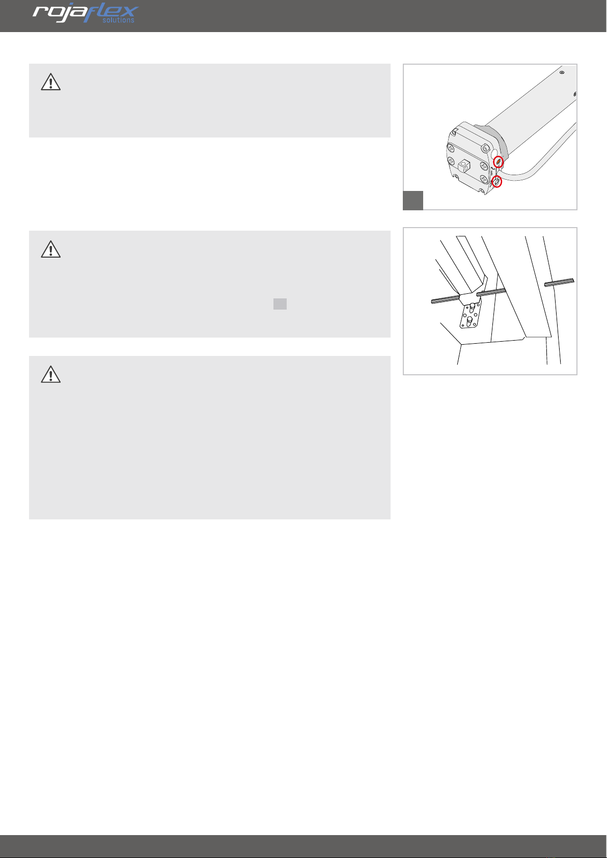
Lay the power cable of the motor in-
ternally in the empty conduit up to the
junction box, observing the local electri-
cal regulations.
Mains cables must not be laid in the
winding space of the plant. Make sure
that the power cable does not come into
contact with moving parts of the plant.
General safety instructions

4 www.rojaex.com
For the electrical connection, a power
connection with 230 V/50 Hz and an on-
site disconnecting device (fuse) must be
permanently available at the installation
site.
To avoid hazards, the power cord may
only be replaced by the manufacturer,
its customer service or a similarly
qualified person.
Only the same cable type may be used,
supplied by the motor manufacturer,
may be used.
Attach permanently mounted control
devices visibly.
Both rated torque and rated operating
time must be compatible with the
characteristics of the driven equipment.
ATTENTION!
Observe the notes on installation and
operation of the system!
There is an increased risk of injury if
this is not observed!
Proper operation of the equipment
is only guaranteed if it is properly
installed, mounted, supplied with
sufficient power and maintained.
Secure the system against unauthorized
operation.
Take safety precautions against
unintentional switch-on.
Before working on the system,
disconnect all connecting lines to be
mounted from the power supply and
secure them against unintentional
reconnection. Remove all lines that are
not required.
Set all devices that are not required
for operation with the motor out of
operation.
Attach the operating element of a
manual release (emergency hand crank)
below a height of 1.8 m.
ATTENTION!
It is essential to observe the
instructions for correct use and the
operating conditions!
There is an increased risk of injury if
used improperly!
Use the motors only for opening and
closing awnings or textile sunshades.
Only use original components and
accessories from the manufacturer.
Instruct all persons in the safe use of the
engine.
Watch the moving equipment and keep
people away from it until the movement
has stopped. Place warning signs on
automatically moving equipment if
necessary.
Prohibit children from playing with
stationary controls or with the remote
control.
Store the handheld transmitter in such
a way that unintentional operation, e.g.
by children playing, is impossible.
Carry out all cleaning work on the
on the sun shading system in a de-
energized state.
Take special care with moving and open
/ extended equipment, as parts may
fall if fastenings (e.g. springs, brackets,
consoles, etc.) weaken or are broken.
General safety instructions

www.rojaex.com 5
IMPORTANT!
Disposal instructions!
European Directive 2012/19/EU (WEEE)
Our electrical and
electronic products
are marked with a
crossed-out wheeled
garbage can, which
indicates that these
products and any
batteries they may
contain must be
collected separately at
the end of their useful life and must not
be disposed of together with normal
household waste.
ATTENTION!
The following mounting instructions
must be observed!
Before mounting, compare the mains
voltage / frequency specifications on
the nameplate with those of the local
mains.
The changeover time for changing the
running direction must be at least 0.5
seconds!
The switches or controls used must
not execute a simultaneous UP/DOWN
command!
Moving parts of motors operating
below a height of 2.5 m above the
ground must be protected.
The winding shaft must be mounted
horizontally! If the hangings are wound
up at an angle, the motor or the
hangings may be damaged.
Inspection openings must be easily
removable and accessible and must not
be permanently closed off inaccessibly.
IMPORTANT!
For permanently installed devices, a
disconnecting device for each phase
must be provided on the part of the
installation in accordance with DIN VDE
0700.
Switches with a contact opening width
of at least 3 mm (e.g. circuit breakers,
fuses or RCDs) are considered to be
disconnecting devices.
The manufacturer's liability for defects
and damage is excluded if these are
due to non-observance of the assembly
and operating instructions (incorrect
installation, incorrect operation, etc.).
General safety instructions

6 www.rojaex.com
The substances contained in these
products may have negative effects on
health and the environment, so users of
electrical products and batteries also have
a responsibility in recycling these waste
materials and in this way contribute to the
protection, preservation and improvement
of the environment.
Obligation for separate disposal
Our duty as manufacturers is, among other
things, to inform you of your obligation to
separate disposal.
• When disposing of products with
batteries, remove them from the
product and dispose of them separately.
• When disposing of illuminants, they
must be disposed of separately to the
receptacle.
Return option and
Recycling program EU
We are connected to public-law return
systems throughout Europe and thus
offer our customers access to a Europe-
wide network of local recycling facilities
(recycling centers, take-back points or
similar).
Our products are professionally recycled
via these local facilities. This reduces the
amount of waste - to the benefit of the
environment.
Our registration numbers:
*For registration data of other European
countries, see Contact Information page.
A take-back by us as manufacturer
according to §19 WEEE is not to be asserted.
Information on the degree of fulfillment
of the collection and recycling
requirements
It is also our duty as a manufacturer to
inform you about the degree of fulfillment
of the collection and recycling requirements.
Since we are connected to a qualified take-
back system, we can refer to the degree of
fulfillment of the recycling companies.
You can find this information on our
website.
Deletion of personal data
Some of our products contain personal data.
This applies in particular to information and
telecommunications technology devices
such as computers and smartphones. In
your own interest, please note that each end
user is responsible for deleting the data on
the old devices to be disposed of!
Reg. no.*
WEEE DE 41060608
Battery DE 88866710
Illuminant
Transport and
Shipping packaging DE5768543732165
General safety instructions

www.rojaex.com 7
Scope of delivery
Compare after unpacking:
• the package contents with the information on the scope of delivery in these instructions.
• the motor type with the corresponding information on the nameplate.
Please refer to the packaging for the type designation,
the technical data from the table above.
If necessary, incomplete devices or devices that do
not comply with the specifications must not be put
into operation and a complaint must be lodged
with our customer service department (see contact information) before the motor is installed!
Drive
(Model / type see package specification)
incl. 3 m connection cable
and adapter/driver (pre-assembled)
- SW70 (MLL-80/15 NHK)
Standard accessories (included in the scope of delivery)
1. Standard star bearing
2. Universal star flat bearing
3. Crank eyelet
4. Motor adjustment pin
Assembly and operating instructions
Motor type
Mains voltage
Mains-
Frequency
Current
recording
Engine power
Output torque
Output speed
Duty cycle
Temperature
range
Protection
class
Insulating
material class
Capacitor
Emission-
sound
pressure-
Dimensions
(mm)
MLL-80/15 NHK 230 V ~ 50 Hz 1,43 A 330 W 80 Nm 15 Min-1 4 Min. -10 °C / +50 °C IP 44 H 14 µF ≤ 70 dB a=667 / B=32
C=620 / d=10
Technical data
d
a
c
b
Jacket pipe diameter: MLL80 NHK = 59 mm
Limit switch range: 22 U
1 2
Technical data / scope of delivery
3 4
Voustrouverez ici une version complète et actuelle du mode d‘emploi/
Puedeencontrar una versión completa actual del manual aquí/
Potetetrovare una versione completa attuale del manuale qui/
Eenactuele volledige versie van de handleiding vindt u hier/
Aktualną,pełną wersję podręcznika można znaleźć tutaj/
Akézikönyv aktuális, teljes verzióját itt találja:
BEDIENUNGSANLEITUNG
Mit mechanischen Endschaltern und Nothandbedienung
Rohrmotor
Rojaex_MLL-80 NHK_manual_V3_2022-05-31
IT
NL
PL
HUN
EN
FR
ES
Original assembly and operating instructions
Instructions de montage et d‘utilisation originales
Instrucciones de montaje y funcionamiento originales
Istruzioni originali per il montaggio e l‘uso
Originele montage- en gebruiksaanwijzing
Oryginalna instrukcja montażu i obsługi
Eredeti összeszerelésiés kezelési útmutató

8 www.rojaex.com
Montage vorbereiten
Note before mounting
1. Read the operating instructions carefully and completely.
2. Make sure that the carrier product (roller shutter, awning) is not
damaged and that it can be opened and closed without interference.
If necessary, replace damaged parts.
Mounting in roller shutter
1. Lower the roller shutter completely and determine whether the
motor is to be installed on the left or right side in the roller shutter
box. Always choose the shortest route to the nearest junction box, as
cables must not be laid in the roller shutter box.
2. The limit switch is controlled via the fully opened plastic ring.
Always ensure that the motor can be pushed into the shaft as far as it
will go.
Structure of the shutter
The drawing below is exemplary
and shows the basic structure of a
roller shutter system.
Deviations from the on-site
installation are possible.
1
1
2
2
3
3
4
4
5
5
6
6
7
7
8
8
Bearing shell Steel shaft Engine mount
Ball bearing Suspension openings Safety split pin
Roller capsule Roller shutter motor
Mounting

www.rojaex.com 9
1
2
3
4
Mounting the motor
1. Lay the connecting cable in an empty pipe up to the junction box,
observing the local building and electrical regulations.
2. Lower the shutter completely and loosen the shaft connection.
3. Disassemble the roller shutter shaft.
4. Mount the motor bearing included in the scope of delivery on the
side on which you want to mount the motor.
The motor can be installed on the left or right.
5. Push the barrel ring adapter over the barrel ring on the motor head
as far as it will go ( 1 ).
Make sure that the groove in the adapter is in the correct position.
6. Push the motor into the roller shutter shaft until it is completely
inserted with the race in the shaft ( 2 ).
ATTENTION!
Never use a hammer when doing this!
Adapters and drivers may not slide in very smoothly,
nevertheless do not hit the motor!
ATTENTION!
The roller capsule or telescopic shaft must be secured
against displacement!
7. Check whether the shaft with the installed motor can be mounted
appropriately in the roller shutter box or whether you may have to
shorten the shaft.
On the counter bearing side (opposite the motor side) is the roller
capsule or telescopic shaft. These can be pushed a few centimeters
into the roller shutter shaft or pulled out of the shaft.
8. Insert the motor inserted into the shaft into the motor bearing and
the shaft with the journal of the roller capsule into the counter
bearing ( 3 ).
Secure the square spigot of the motor head with the locking pin
included with the bearing.
9. Fasten the roller capsule with two opposite screws ( 4 ).
NOTE!
The roller capsule (counter bearing side) is usually
secured with 2 opposite screws.
Mounting

10 www.rojaex.com
5
Mounting
ATTENTION!
Do not drill into the motor's jacket tube and do not turn
any screws into the motor!
ATTENTION!
Use steel band hangers, also called securing springs, to
secure the shutter to the shaft.
If you screw screws into the roller shutter shaft to
suspend the roller shutter, please ensure that they are
short enough and do not touch the motor under any
circumstances!
When installed, the rolled-up roller shutter must run vertically into the
guide rail.
Make sure that the bearings or the shaft are installed horizontally.
An oddly wound roller shutter can block and destroy the motor.
ATTENTION!
Make sure that the motor is mounted so that the
adjustment screws on the motor head ( 5 ) remain easily
accessible!

www.rojaex.com 11
Wiring diagram - motor with mechanical limit switches
WARNING!
There is a danger to life from electric shock when working on electrical equipment!
• The mains connection of the motor and all work on electrical installations may only be
carried out by an authorized electrician in accordance with the respective connection
diagrams of the device.
• Carry out all assembly and connection work in a de-energized state.
NOTE!
After connecting the control/switch, check the UP, STOP and DOWN functions.
The direction of rotation of the motor depends on the installation position (left/right) of
the motor as well as on the winding direction of the roller shutter (left roller/right roller).
If the motor (shutter) should move in downward direction when the UP key is pressed,
the brown and black wires (UP/DOWN) must be swapped.
Electrical connection
black: L1 Direction of rotation 1
brown: L2 Direction of rotation 2
blue: N Neutral
green-yellow: PE Protective earth
Switch box
Switch box
black (brown)
|brown (black)
blue

12 www.rojaex.com
ATTENTION!
Switches and circuits (controls) must not allow simultaneous UP and DOWN commands!
An UP and DOWN command given at the same time will cause a short circuit of the
operating capacitor.
Only electrically or mechanically interlocked switches (not light switches) may be used.
ATTENTION!
An impermissible parallel connection ( 1 ) leads to the destruction of the limit switches!
It must be ensured that each drive has its own switching contact for each running
direction!
To control multiple drives with only one switch (or timer), be sure to use a motor
isolating relay or suitable motor control units!
Electrical connection
impermissible parallel connection

www.rojaex.com 13
Set end positions (end points)
1. Connect the motor according to the wiring diagram (page 11) and
switch on the power supply.
2. Move the shaft with the motor down via the DOWN button on the
control unit until the motor switches off and the factory final setting is
reached (roller shutter not yet fastened!).
The factory setting is approx. 3-5 full shaft revolutions between OPEN
and CLOSE.
3. Attach the roller shutter to the roller shutter shaft ( 1 ) ( 2 ).
If the suspension openings on the roller shutter shaft cannot be
reached, press the DOWN button on the control unit again and turn
the adjustment pin on the upper adjustment screw ( 3 ) in the "+"
direction. The shaft then moves jerkily in the DOWN direction.
Turn the adjustment screw until you reach the suspension openings
for the steel band hangers and can hang the roller shutter.
1
2
3
4
ATTENTION!
If the shaft does not immediately move in the DOWN
direction when you turn the adjusting screw ( 3 ) to "+",
you have accidentally turned the wrong adjusting screw!
Turn the other adjustment screw 1-2 turns also in the "+"
direction to check this.
NOTE!
The roller shutter end strip must still be visible from the
outside ( 4 ).
4. Move the roller shutter in the OPEN direction.
The motor must switch off before reaching the roller shutter box.
Then turn the adjusting pin on the lower adjusting screw ( 3 ) in the
"+" direction.
The motor (roller shutter) now moves "jerkily" upwards.
Continue turning the adjustment screw until the roller shutter has
reached the roller shutter box or the desired end point.
Set

14 www.rojaex.com
ATTENTION!
Note that the limit switches of the motor only function
properly when the motor is correctly and completely
inserted into the shaft!
The arrows indicate the
direction of rotation of
the shaft.
The adjustment screws
next to it are
only responsible for
this one direction of
rotation.
Turn the adjusting
screw in the direction of
"minus
- the motor no longer
moves as far in this
direction.
Turn the adjusting screw
in the "plus" direction
- the motor moves
"jerkily" in this direction.
If the shutter does not stop before reaching the shutter box, stop it
with the STOP button on the control unit.
Then move the roller shutter back a little (approx. "half opening") and
turn the adjusting pin on the lower adjusting screw (3) a few turns in
the "-" direction.
Then move the shutter back in the OPEN direction and check that the
motor now stops before reaching the shutter box.
If necessary, move the roller shutter back a little again and reduce
the travel distance further by turning the adjustment screw in the "-"
direction.
Then move the shutter back in the OPEN direction and make the fine
adjustment.
To do this, turn in the "+" direction until the desired switch-off point is
reached.
Once the shutter has reached the desired opening height, remove the
adjustment tool.
Now allow the roller shutter to roll up and down completely several
times as a test. If the roller shutter stops at the set end points, the limit
switch setting is complete and the roller shutter box can be closed.
ATTENTION!
Please note that the motor is equipped with a thermal
protection switch and it may happen that the motor
switches off because it has reached a high temperature
after a few runs. In this case, the motor switches off
automatically for safety reasons.
After approx. 15-20 minutes cooling time the motor is
ready for operation again.
Set

www.rojaex.com 15
Change end positions (end points)
Move the shutter back to the middle position and start again from the
beginning.
To do this, first move the roller shutter to a "middle position" (roller
shutter approx. half open).
Then turn the corresponding adjustment screw a few (5-6) turns in the
"-" direction and check again whether the motor now stops earlier.
If necessary, start from the beginning.
In the factory, approx. 3-5 full shaft revolutions are set as limit switch
range between OPEN and CLOSED.
If the motor does not stop in time, one of the adjustment screws may
have been turned in the wrong direction too often.
Then unhook the shutter again and let the motor in the shaft run in the
DOWN direction until it switches off automatically.
Once this is done, you can determine if you are using the correct
adjustment screw for the appropriate direction of rotation by turning
one of the adjustment screws in the "+" direction.
Make sure that the motor is still controlled by the control unit (press
the DOWN key again).
NOTE!
If the motor travels too
far up or down (does
not stop when reaching
the roller shutter box
or the lower end point),
the adjusting screw
responsible for this
direction of travel must
be turned in the "-"
direction to shorten the
travel distance.
ATTENTION!
Do not perform a "test run on the table", as this will not
rotate the race adapter on the motor head.
The motor then does not switch off and runs "endlessly"!
This very quickly leads to overheating and shutdown of
the motor by the built-in thermocouple.
It is also not advisable to turn the adjusting screws
before installing the motor in the shaft, as this usually
leads to an uncontrolled adjustment of the end positions
set at the factory.
Set

16 www.rojaex.com
ATTENTION!
Note motor head
position / gearbox input
for crank rod.
Straight crank eye (included in the scope of delivery of the NHK motors)
Loosen the locking screw at the lower end of the crank eyelet and remove the washer.
Insert the crank eye into the emergency manual gear unit on the motor head, place the washer
underneath and fix the crank eye with the screw.
Joint crank eyelet (available as accessories)
Mount the motor in the roller
shutter box according to the
instructions.
Drill passage for the crank rod
through the masonry (the box).
Determine hole diameter by
measuring the crank rod.
The crank rod must have sufficient
"play" and must not drag on the
masonry (the box).
Insert the crank rod through the
wall into the emergency manual
gearbox of the motor.
Fixing the crank rod to the motor
head is not necessary, because
the crank joint is fixed to the
masonry (the box) with the
mounting plate.
Room side
Mount crank eyelet
-10
-10
0
-30
-25
-20
-15
-5
-5
-10
-10
0
-30
-25
-20
-15
-5
-5
1
-10
-10
0
-30
-25
-20
-15
-5
-5
-10
-10
0
-30
-25
-20
-15
-5
-5
-10
-10
0
-30
-25
-20
-15
-5
-5
-10
-10
0
-30
-25
-20
-15
-5
-5
-10
-10
0
-30
-25
-20
-15
-5
-5
1
-10
-10
0
-30
-25
-20
-15
-5
-5
-10
-10
0
-30
-25
-20
-15
-5
-5
-10
-10
0
-30
-25
-20
-15
-5
-5
-10
-10
0
-30
-25
-20
-15
-5
-5
-10
-10
0
-30
-25
-20
-15
-5
-5
1
-10
-10
0
-30
-25
-20
-15
-5
-5
-10
-10
0
-30
-25
-20
-15
-5
-5
-10
-10
0
-30
-25
-20
-15
-5
-5
123

www.rojaex.com 17
NOTE!
The crank must be
available at all times in
case of emergency!
Therefore, store the crank
in an easily accessible
place or leave it on the
crank eyelet.
Fix the mounting plate of the
crank joint to the masonry (the
box).
Ensure that the mounting plate is
seated straight!
For manual operation of the motor
in case of power failure a crank
handle (Crank not included) into
the crank eyelet and open or close
the roller shutter with the crank.
ATTENTION!
Disconnect the motor from its power source (fuse OFF) when operating the emergency
hand crank.
When operating the emergency hand crank, make sure that the end points are NOT
overrun!
After operating the emergency hand crank, before moving the roller shutter or awning
with the motor again, crank it to the "middle position" to ensure that the end points
have not been overrun.
Mount crank eyelet
-10
-10
0
-30
-25
-20
-15
-5
-5
-10
-10
0
-30
-25
-20
-15
-5
-5
1
-10
-10
0
-30
-25
-20
-15
-5
-5
-10
-10
0
-30
-25
-20
-15
-5
-5
-10
-10
0
-30
-25
-20
-15
-5
-5
-10
-10
0
-30
-25
-20
-15
-5
-5
-10
-10
0
-30
-25
-20
-15
-5
-5
1
-10
-10
0
-30
-25
-20
-15
-5
-5
-10
-10
0
-30
-25
-20
-15
-5
-5
-10
-10
0
-30
-25
-20
-15
-5
-5
5
4

18 www.rojaex.com
The motor does not raise or lower the shutter, starts
too slowly or with loud noises.
Possible cause 1:
• The connections are not correct.
Solution 1:
• Check connections.
Possible cause 2:
• Incorrect installation or overload
Solution 2:
• Check installation and shutter load.
The shutter stops during lifting or lowering.
Possible cause 1:
• Set end point is reached.
Solution 1:
• Set end points again according to instructions.
Possible cause 2:
• Operating time has been exceeded (4 minutes).
Solution 2:
• Allow engine to cool for approx. 20 minutes.
Possible cause 3:
• Blocking due to obstacle or icing
Solution 3:
• Check and remove obstruction or icing if necessary.
The engine does not run.
Possible Cause:
• The mains voltage is missing.
Solution:
• Use a voltmeter to check whether the supply voltage (230 V) is
present and check the wiring.
Pay particular attention to the information on impermissible
connection types.
• Check installation.
The engine no longer runs or becomes extremely hot.
Possible Cause:
• "Test run" of the motor outside the shaft (motor in uninstalled
condition).
Motors convert unneeded power into heat!
Solution:
• Allow the motor to cool down for approx. 20 minutes and only
switch on when assembled.
The motor does not stop automatically during
adjustment work and test run.
Possible cause 1:
• The adapter has slipped off the race on the motor head.
Solution 1:
• Check that the adapter sits flush in front of the motor head and is
fully inserted in the shutter shaft.
• Push the adapter flush in front of the motor head and push the roller
shutter shaft completely onto the adapter.
• Reset end points.
Possible cause 2:
• Roller capsule is not fixed or roller shutter shaft is too short.
Solution 2:
• Fix roller capsule or insert suitable roller shutter shaft.
The motor moves in the wrong direction at the push of
a button.
Cause:
• Black and brown wires (UP/DOWN) incorrectly connected.
Solution:
• Change the direction of rotation of the motor and swap the brown
and black wires (UP/DOWN) (see page 13).
The motor stops or does not start during adjustment
work or normal operation.
Possible Cause:
• Thermal protection has addressed.
Solution:
• Allow engine to cool for approx. 20 minutes.
The roller shutter stops when raised - motor hums
Possible Cause:
• Obstacle in the running rail / obstacle on the roller shutter curtain
(dirt / icing etc.).
Solution:
• Remove the obstacle. Release the roller shutter in the downward
direction.
Troubleshooting / FAQ

www.rojaex.com 19
Declaration of conformity
Konformitätserklärung
ORIGINAL EU/EC DECLARATION OF CONFORMITY
ORIGINAL EU/EG KONFORMITÄTSERKLÄRUNG
We, Schoenberger Germany Enterprises GmbH & Co. KG, Zechstr. 1-7, D-82069 Hohenschäftlarn, Germany
declare under our sole responsibility that the Rojaflex branded product:
Wir, die Schoenberger Germany Enterprises GmbH & Co. KG, Zechstr. 1-7, D-82069 Hohenschäftlarn, Deutschland
erklären unter unserer alleinigen Verantwortung, dass das mit der Marke Rojaflex versehene Produkt:
Document no. / Dokument-Nr. CE_ROJ_MLL-80/15 NHK_2022-01-04 (Update LVD 2022)
Brand / Marke Rojaflex
Model / Modell MLL-80/15 NHK
Product Type / Produkttyp Motorisation for shutter, awning, blind and similar equipment
Antriebe für Rollläden, Markisen, Jalousien und ähnliche
Einrichtungen
Serial number from / Seriennummer ab: xx_01_2022 (day/month/year) or 01/22 (week/year)
when uses as intended, according to his instructions, complies with the essential requirements of the following
directives:
den einschlägigen Bestimmungen der folgenden Richtlinien entspricht, wenn es nach den Anweisungen des Herstellers
bestimmungsgemäß verwendet wird:
Machinery directive 2006/42/EC
Maschinenrichtlinie 2006/42/EU
Electromagnetic compatibility directive (EMC) 2014/30/EU
Richtlinie Elektromagnetische Verträglichtkeit 2014/30/EU
Low Voltage Directive 2014/35/EU
Niederspannungsrichtlinie 2014/35/EU
Restriction of the use of certain Hazardous Substances directive (RoHS) 2011/65/EU and 2015/863/EU
RoHS Richtlinien 2011/65/EU und 2015/863/EU
The following standards were applied to assess the conformity:
Die Konformität wird durch die Einhaltung folgender Normen nachgewiesen:
EN 60335-2-97:2006/A12:2015
EN 60335-1 :2012/A2:2019
EN 55014-1:2017
EN 55014-2:2015
EN 61000-3-2:2014
EN 61000-3-3:2013
Attestation of Conformity:
N8A 088081 0127 Rev.00 ((LVD 2014/35/EU) 2022-01-04
T8A 088081 0073 Rev. 00 (EMV 2014/30/EU) 2019-05-15
TÜV Süd
This declaration loses its validity in case of improper use and changes of the system or product that has not been agreed with the manufacturer.
Diese Erklärung verliert Ihre Gültigkeit bei nicht bestimmungsgemäßer Verwendung und bei Änderungen der Anlage bzw. des Produktes,
die nicht mit dem Hersteller abgesprochen wurden.
Hohenschäftlarn, 2022-01-04 Michael Mayer
CEO / Geschäftsführer
Declaration of Conformity
Aktuelle EU-Konformitätserklärungen sind unter der folgenden Internetadresse verfügbar:
www.rojaflex.com/konformitaetserklaerungen.html

Reprints, including excerpts, only with the permission of the author.
Product changes, which from our point of view serve to improve quality,
can be made at any time, even without prior notice or notification.
Illustrations can be example illustrations, which differ in appearance from
the delivered goods.
Errors excepted. No liability is assumed for printing errors.
Our general terms and conditions apply.
If you have any questions about this product,
please contact us at the following address:
rojaflex
is a registered trademark of
Schoenberger Germany Enterprises GmbH & Co. KG
Zechtraße 1-7
82069 Hohenschäftlarn
Germany
T +49 (0) 8178 / 93 29 93 93
F +49 (0) 8178 / 93 29 93 94
info@rojaflex.com
www.rojaflex.com
EU Waste and recycling / Registrations
Germany for electrical devices:
Stiftung EAR
WEEE-Reg.-no.: DE 41060608
Germany for batteries:
Stiftung EAR
Batt-Reg.-no.: DE 88866710
Germany for packaging:
LUCID Reg.-no.: DE5768543732165
Austria for electrical devices:
Elektro Recycling Austria (ERA) GmbH
ERA Contract no: 40801
Austria for packaging:
Altstoff Recycling Austria (ARA) AG
ARA License number: 23363
Switzerland for electrical devices:
Stiftung SENS
Membership number: VP11544
France for electrical devices:
Ecologic
Membership number / Take-back system: M3670
National registry: UIN FR208795_01SUIN
France for packaging:
Citeo
Membership number / Take-back system: 532886
National registry: UIN FR208795_01SUIN
Spain for electrical devices:
ECOTIC
Reg.-no.: RII-AEE- 7601
Spain for packaging:
Ecoembes
Membership number: 97556
Italy for electrical devices:
Raccolta differenziata. Verifica le disposizioni del tuo Comune!
Reg.-no.: n/a
Italy for packaging:
Raccolta differenziata. Verifica le disposizioni del tuo Comune!
Membership number: n/a
Table of contents
Other rojaflex Engine manuals
Popular Engine manuals by other brands

SOMFY
SOMFY Glydea Ultra RTS Series instructions

Mitsubishi
Mitsubishi S16R-Y1PTA Operation & maintenance manual

Suzuki
Suzuki DF 25 General information

MerCruiser
MerCruiser 496 MAG Bravo owner's manual

Doosan
Doosan D1146 Installation operation & maintenance

STEPCRAFT
STEPCRAFT HF350 Operating/safety instructions