manuals.online logo
Brands
  1. Home
  2. •
  3. Brands
  4. •
  5. Roland
  6. •
  7. Musical Instrument
  8. •
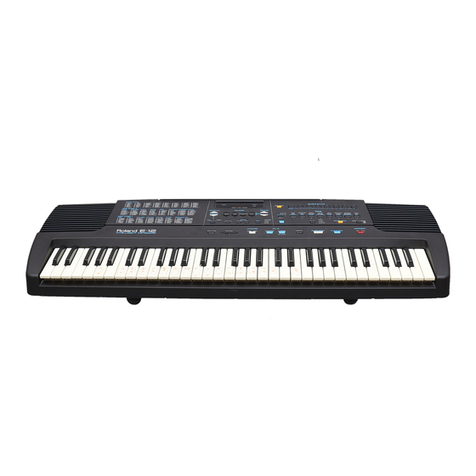
  9. Roland KR-4500 Operating and maintenance manual

Roland KR-4500 Operating and maintenance manual

Other Roland Musical Instrument manuals

Roland HP 900 User manual

Roland

Roland HP 900 User manual

Roland V-Accordion FR-1 User manual

Roland

Roland V-Accordion FR-1 User manual

Roland Fantom-G none Instruction manual

Roland

Roland Fantom-G none Instruction manual

Roland FR-2 V-Accordion User manual

Roland

Roland FR-2 V-Accordion User manual

Roland RD-64 User manual

Roland

Roland RD-64 User manual

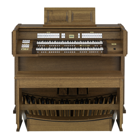
Roland KR-115 Manual

Roland

Roland KR-115 Manual

Roland RD-200 User manual

Roland

Roland RD-200 User manual

Roland HP 335 User manual

Roland

Roland HP 335 User manual

Roland GP-9M Manual

Roland

Roland GP-9M Manual

Roland RMP-1 User manual

Roland

Roland RMP-1 User manual

Roland HP103e User manual

Roland

Roland HP103e User manual

Roland DP-900 User manual

Roland

Roland DP-900 User manual

Roland VS-1880 User manual

Roland

Roland VS-1880 User manual

Roland FA 08 User guide

Roland

Roland FA 08 User guide

Roland FP-50 User manual

Roland

Roland FP-50 User manual

Roland FR-8X Operating instructions

Roland

Roland FR-8X Operating instructions

Roland DP603 User manual

Roland

Roland DP603 User manual

Roland G-70 User manual

Roland

Roland G-70 User manual

Roland DP-900 User manual

Roland

Roland DP-900 User manual

Roland Atelier AT90 User manual

Roland

Roland Atelier AT90 User manual

Roland HP 1500 User manual

Roland

Roland HP 1500 User manual

Roland RG-1 User manual

Roland

Roland RG-1 User manual

Roland RD-150 Operating and maintenance manual

Roland

Roland RD-150 Operating and maintenance manual

Roland HP504 User manual

Roland

Roland HP504 User manual

Popular Musical Instrument manuals by other brands

Funkey SP-561 user manual

Funkey

Funkey SP-561 user manual

thomann DP-275 GP BP user manual

thomann

thomann DP-275 GP BP user manual

Kawai CN17 Operation guide

Kawai

Kawai CN17 Operation guide

Yamaha PCY130 owner's manual

Yamaha

Yamaha PCY130 owner's manual

Johannus Rembrandt 200 user manual

Johannus

Johannus Rembrandt 200 user manual

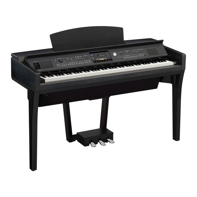
Yamaha Clavinova CVP-609 Reference manual

Yamaha

Yamaha Clavinova CVP-609 Reference manual

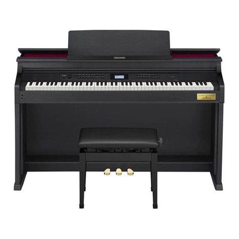
Casio celviano ap-700 user guide

Casio

Casio celviano ap-700 user guide

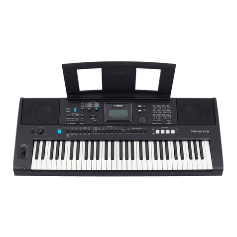
Yamaha PSR-E473 owner's manual

Yamaha

Yamaha PSR-E473 owner's manual

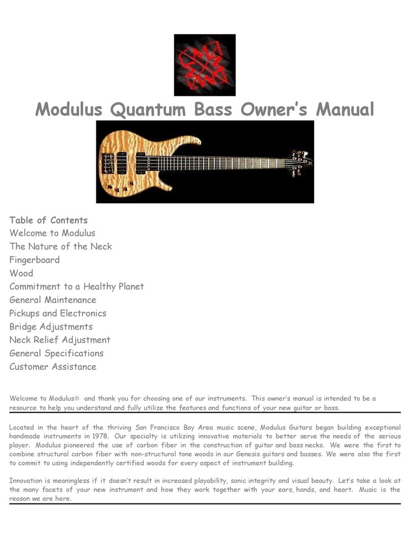
Modulus Quantum Series owner's manual

Modulus

Modulus Quantum Series owner's manual

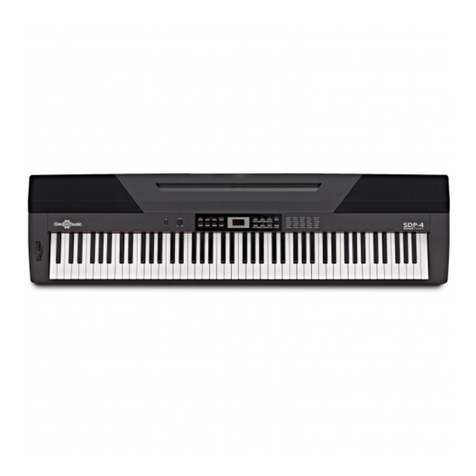
Gear4music SDP-4 user manual

Gear4music

Gear4music SDP-4 user manual

HOMCOM 390-006 Assembly instruction

HOMCOM

HOMCOM 390-006 Assembly instruction

Xotic Guitars ProVintage Series owner's manual

Xotic Guitars

Xotic Guitars ProVintage Series owner's manual

Sadowsky MetroLine Series operating manual

Sadowsky

Sadowsky MetroLine Series operating manual

Bosendorfer CEUS user manual

Bosendorfer

Bosendorfer CEUS user manual

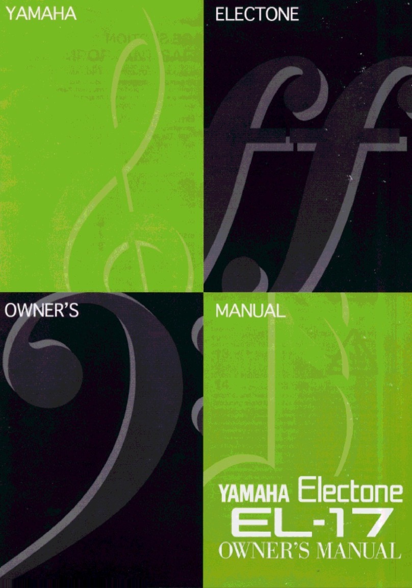
Yamaha Electone EL-17 owner's manual

Yamaha

Yamaha Electone EL-17 owner's manual

Alesis AHB-1 Assembly guide

Alesis

Alesis AHB-1 Assembly guide

Hotpoint RF512GP How to get the best

Hotpoint

Hotpoint RF512GP How to get the best

Yamaha DGX-530 manual

Yamaha

Yamaha DGX-530 manual

manuals.online logo
manuals.online logoBrands
  • About & Mission
  • Contact us
  • Privacy Policy
  • Terms and Conditions

Copyright 2025 Manuals.Online. All Rights Reserved.

Apr,
1992
KR-4500
KR-4500
|
First
Edition
DIGITAL
INTELLIGENT
PIANO
eit
2
supeceuenr.
is
attached
at
the
end
of
the
page
TABLE
OF
CONTENTS
AX
Page
SPECIFICATIONS
«ts
treet
ttre rece
eene
seen
fe
|
nnn
1
LOCATION
OF
CONTROLS
«ccrtttttttereneeeee
INA
IVACB
RY]
ccc
ccc
eee
es
1,
2
EXPLODED
VIEW
1
trttttttrtt
tess
steeteseeees
aS
41
3
EXPLODED
VIEW
2
«screcerert
cette
eee
eneees
aN
|
42
4
KEY
BOARD
PARTS
LIST
«sett
etttetrtterereeee
ct
2
nn
i
ae
5
KEY
BOARD
DISASSEMBLY
«ccttttttttttteere:
PERE)
RIB
cc
ccc
ee
eee
5
~10
IDENTIFYING
VERSION
NUMBER
«
«+++
++
++++***
KR-DS
VP
VINOD
ccs
eee
10
FACTORY-SET
DATA
LOADING:
«+++
trrrresteees
TBH
TRE
—
OO
—
BFR
cece
ees
eee
eee:
10
PARTS
LIST
««trttrctteeees
stent
eee
eens
hy
A.
11,
12
DATA
SAVING/LOADING
«tcctcsstsststeeeeeeeee
F-ANt-—TY/au-
RAR
ccc
t
cet
eee
cease
13
TEST
MODE
«ster
eres
cette
nent
e
nena
FR
REM
KK
crete
eee
eee
eee
eee
enews
13~17
STAND
EXPLODED
VIEW:
«rrr
ttttttereeeeees
RADY
KEBBB
cece
eee
cence
eee
eee
eens
18
PEDAL
UNIT
EXPLODED
VIEW:
::
+:
test
eteceres
ARAMA
vy
RSYRRRY
ccc
cece
eee
eee
eens
18
STAND
KRS-4500
PARTS
LIST
«s++rtttttssteee
REY
KF
KRS-4500
YY
UA
Reve
cece cece
eee
19
BLOCK
DIAGRAM
t:sssstteeeneseeeeneneneeenee
ae
RAS
20
SK-6L88-B
PCB
ASS'Y
«ss
tttteceeseeeeeeeeeeeee
SK-6L88-B
PCB
ASS'Y
«crests
tesereseneeeeenees
24
PS.
AMP-BOARD
ASS'Y
230V/240V
«+++
+s
seeeee:
PS.
AMP-BOARD
ASS'Y
230V/240V
-++++++::
22,
23
MAIN
BOARD
ASS'Y
««rcesrtteereteeeeneeeneeee
MAIN
BOARD
ASS'Y
«ssretetrertceceeneneee
24,
25
PANEL
BOARD
ASSYY
«s:rttetetetteeeneeneeeee
PANEL
BOARD
ASS'Y<ssttettetetereneneeee
26,
27
CHANGE
INFORMATION
«ccceteee:
wee
2
ce
a
28
APPENDIX-INSPECTION
SPECIFICATIONS
-::-::
FESR
“PREMLAR”
ccc
ccc
tcc
rece
ee
cece
seneens
29
TROUBLESHOOTING
«ctttttttteteneeneneennes
a
|
ye
eal
ae
aa
29,
30
Printed
in
Japan
(AGDO)
(CR)
1
{f€
Roland
17059638
SPECIFICATIONS/{t##
OKEYBOARD
.---------ss-
eee
sserettttetectttetentnnee
:
88keys.(SK-6L88-B)
w/velocity.
OACCESSORIES
©
-0-----s
eee
etnies
OVOICES
-3:3:s2cn
dence
eset
he
-
28
voices
Maximum.
OPRESET
TONE
..-----------000
eset
eee cee
eeeeeeee
:
40.
(Tone
Expansion
Mode
:
128)
ORHYTHM
TONE
...--------0:-:-00-0:ecceceeeseeecteeeneee
:
47.
(Manual
Drums)
OMUSIC
STYLES...-----------
ee
eee
ce
:
32.
(Music
Style
Expansion
Mode
:
64)
OQEFFECTS
-----------:-
ce
cceseeeettece
eet
ee
etteeetctes
:
Reverb
:
8,
Chorus
:
4
OCOMPOSER
..-------------
eects
:
Record
&
Play
(6
track
music
recorder)
ODISPLAY
----------0-
ees
ee
eee
ete
teen
ees
eeeencenenees
:
16
characters
x
2
lines
w/back
light.
OINPUT
LEVEL
-----------::-e:
cc
eseecesecreeseeeseeeeeee
-0dBm.
OQOUTPUT
LEVEL....-------:-----
te
eeiee
:
+2
dBm.(Volume
:
max.,
Brilliance
:
center,
)
(C4
key
velocity
:
7F,
Tone
:
PIANO
1
)
OQOUTPUT
POWER.
..-------:-::
cette
:
30W
x2
COSPEAKERS
0000s
ees
secs
eestesetees
tees
eecenscennenes
:
2
way
:(5cm
x2,20em
x2)
O©OPOWER
CONSUMPTION
.....---------------
:
B5W(100V),
9OW(117V/230V/240V)
ODIMENSIONS
...--------eeeeceeeeteeeeeceeeesceteneents
:
-Main
Unit(KR-4500)-
56(W)
x
20-5/8(D)
x
8-5/8(H)
inches.
1421
(W)
x
524(D)
x
219(H)
mm
-Stand(KRS-4500)-
56(W)
x
17-7/8(D)
x
25-1/8(H)
inches.
OOPTIONS
+e
eee
reee
eect
ees
tess
tee
tess
eeseeesnenane
:
1421(W)
x
454(D)
x
638(H)
mm
-Total-
56(W)
x
20-5/8(D)
x
33-5/16(H)
inches.
1421(W)
x
524(D)
x
847(H)
mm
OWEIGHT
|:
:e35eee
eee
atetenin
:
-Main
Unit(KR-4500)-
120
1b./54.5kg
-Stand(KRS-4500)-
37
1b.
15
02./17.2kg
-Total-
157
lb.
15
02./71.7kg
LOCATION
OF
CONTROLS//\
%
JLAC
El
——INPUT——
=
——OUTPUT——
RL
(MONO)
RL
(MONO)
EXP
PEDAL
MIDI
Connector
‘Monoral
Jack
~
Stereo
Jack
YKF51-5046
YKB21-5012
YKB21-5010
(13429273)
(13449146)
(13449145)
A,
AC
Cord
(Detachable
/
Rist)
100V
DC-357-J01
(13439816F0)
o<—__—————
Buiton
117V
UC-704-J01
(1343981
2F0)
(22495576)
230V
EC-210-J06
(13439813F0)
A.
Power
Switch
240VE
57226604606
(23495110)
A\
AC
Cord(Detachable/#
Hii
xt)
DC-357-J01(100V)
:
PNo.
13439816F0
UC-704-J01(117V)
:
PNo.13439812F0
EC-210-J06(230V)
:
PNo.13439813F0
57226604606(240VE)
:
PNo.23495110
SC-415-J06
3P(240VA)
:
PNo.13439814F0
Music
Rack
Assy
:
PNo.22195663
Manual
Drum
Sheet
:
PNo.26045820
SMF
template
:
PNo.26045823
Demo
Song
Disk
MF-2DD
:
PNo.22405299
Owner's
Manual!
Set(Japanese)
:
PNo.26045818
Owner's
Manual
Set(English)
:
PNo.26045819
3.5inch
Micro
Floppy
Disk
1
PN,
#8
MF-2HD
NOTE
:
The
above
part
(MF-2HD)
does
not
supply
as
replacement
parts,
because
it
is
options.
JE:
LECO#BBaR
(MF-2HD)
(¢,
MATT
OTC,
HiEABMe
LTH
CAETA,
Stand
sesiiaistiacsrrnmiascan
-
KRS-4500
Music
Style
Catd
«ee
:
TN-SC
series
3.5inch
Micro
Floppy
Disk
---:
MF-2DD/2HD
Chali
#sc+:ss0-tstsnticteccamncctevicesvnss
:W-7R
Head
Phone
«er
eeceee
:
RH-20/80/120
Connection
Cable
+--+
>
PU-1M
MIDVSYNC
Cable
«ee
:
MSC
series
Expression
Pedal
-----.---+----+
>
EV-5
|
SDDGA3078A
240VA
SC-415-J06
3P
(1349814F0)
.
ne
am
(100/240V)
(13129124)
(13429718)
Bender
Wheel
fereeaa
beeON)
BW-C0001
(23285159)
Card
Holder
(22205705)
IC
Card
Connector
[E|
FDD
Unit
7508095A
FZ-357
318F1DR
(13429233)
(22405255)
LED
(red)
es
ey,
HLMP-1301-010
a
S|
)
(
(15029280)
Stereo
Jack
w/Sw
YKB21-5006
ra
Rice
apeee
MUSIC
STYLE
CARD
KR-4500
LOCATION
OF
CONTROLS//\
%
JLAcea
A/Keytop
S
1P
BLK
Apr,
1992
Note
:
With
the
exception
of
the
power
indicator
LED
and
some
tempo
indicator
LEDs,
all
LEDs
(red)
use
the
SLR-34VC
80P215
(PNo.
15029349).
TE
|
BYRGORASLED,
7
Y
RRARALEDO
1
BLS.
F~CLED
(red)
A/Keytop
D
1P
BLK
w/Window
22495218
=
(22
pe
(
SLR-34VC
80F215
(PNo.15029349)
78H
SITET
6
A/Keytop
D
1P
BLK
w/Window
A/Keytop
D
2P
BLK
w/Window
(22495223)
(22495224)
.
Button
IS-Knob-S
BLK/LWG
A/Keytop
S
1P
BLK
A/Keytop
D
2P
BLK
w/Window
A/Keytop
S
4P
BLK
(22495576)
(22485302)
(22495218)
(22495224)
(22495222)
A
Power
Switch
Pot.
SDDGA3078A
|
EWA-NA5X10B54
50KB
A/Keytop
S
4P
BLK
(13129124)
(13339477)
(22495222)
BRILLIANCE
——__1___
nnn
8
AL
ANCE
|
=m
REVERB
=—KEYBOARD
MODE==—=
=
Luwex
MUSIC
STYLE
MELLOW
_
v
BRIGHT
cy
Ci
=a
SHIFT
ACCOMP
_LOWER
ON/OFF
TYPE
WHOLE
LAYER
SPLIT
ON/OFF
CARD
A
AB
por
POP
2
POP
3
POP
4
DANCE
FUNK
SLOW
ROCK
COUNTRY
_
tt.
|
oo
Cc
=
=
ry
Bp
SWING
SLOW
SWING
BIG
BAND
BOOGIE
ROCK'N'ROLL.
BALLAD
MARCH
WALTZ
ON
OFF
VOLUME
co
OFF]
|
<==
CHORUS
==
ARRANGER
=
MANUAL
BASS
POWER
MIND
1
trot
tot
4 a
a
UMAX
co
‘|
|
ON/OFF
TYPE
ON/OFF
INTELLIGENCE
HOLD
my
ON/OFF
‘=a
8
ABP
secat}
8BEAT2
8BEAT3
8B8EAT4
16BEEAT1
16BEEAT
2
16BEEAT3
16BEEAT
4
Fo
|
es
—
=
a
=]
—
DRUMS
CC
——a
—
BASS
7
c—
Cc
Cc
IS-Knob-S
BLK/LWG
DS-Keytop
MD1H
BLK
w/Window
(22485302)
(22495277)
Pot.
EWA-NAOX10B14
10KB
A/Keytop
S
3P
BLK
(13359355)
(22495221)
DS-Keytop
MD2H
BLK
w/Window
(22495278)
DS-Keytop
MD1H
BLK
w/Window
22495277
DS-Keytop
MD1H
BLK
w/Window
( )
(22495277)
LCD
Cover
(22045421)
LOD
Unit
AlKeytop
S
2P
BLK
LM162AS7
(22495220)
(15029546)
:
LCD
Holder
A/Keytop
D
2P
BLK
w/Window
(22205720)
(22495224)
UPPER
A
A
Be
PIANO
1
1
EXIT
ENTER
Co Co
ONE
TOUCH
PROGRAM
MELODY
INTELLIGENCE
PIANO
SPLIT
PIANO
STYLE
woes
ARRANGER
=e
PIANO
2.
HONKYTONK
eg
mead
Cursor
—
B
fe
BRASS
SYNTH
BRASS
TRUMPET
LOWER
A
Pe
STRINGS
1
STRINGS
2
U4
cy
CC):
°C)
B
Bm
acuiTaR
E
GUITAR]
EGUITAR2
ACCORDION
SAW
WAVE
me,
WOOO
BASS
FINGERED
B
PICKED
8
FRETLESSB
SLAP
BI
ee
SAMBA
LATIN
CHA
CHA
MANBO
“460
REGGAE
Bf
BAROQUE
=
BOSSANOVA
mf
=
stows
1
+}
to
t
@
+b
9
4
4
8
FAST
tL
___
=
——_sf
|
Ot
|
C4
VARIATION
TO
oe
|
——
INTRO/ENDING
START/STOP
TEMPO
IS-Knob-S
BLK/LWG
DS-Keytop
MX2H
BLK
(22485302)
(22495275)
FOr
EWA-PFEX10B14
10KB
DS-Keytop
MX1H
BLK
(13339611)
(22495274)
DS-Keytop
MD1H
BLK
w/Window
DS-Keytop
MX1H
C.GRY
(22495277)
DS-Keytop
MD3H
BLK
w/Window.
(22495279)
A/Keytop
S
3P
BLK
RESET
STOP
DS-Keytop
MX4H
BLK
(22495271)
DS-Keytop
MX3H
W.GRY
LED
(green)
(22495343)
SLR-34MC
80F215
(15029348)
pee
ved)
SLR-34VC
80F215
(15029349)
DS-Keytop
MX1H
BLK
(22495274)
DS-Keytop
MX1H
MAROON
(22495342)
(22495341)
A/Keytop
D
1P
BLK
w/Window
(22495221)
(22495223)
A/Keytop
S
1P
BLK
‘A/Keytop
D
2P
BLK
w/Window
(22495218)
(22495224)
TONE
SELECT
er
a
HARPS!
E.PIANO
1
€.PIANO
2
VIBRAPHONE
MARIMBA
om
LRIVS
7
pedclitaa
=
CS):
C2):
Fe):
7
8
MUTED
TP
SAX
OBOE
CLARINET
FLUTE
—
a
a
|
C—_}—____
A/Keytop
S1PC.
GRY
VIOLIN
CHOIR
VOICE
E.ORGAN
1
E.ORGAN
2
PIPE
ORGAN
ene
TRACK
;
;
(22495339)
uf
=
}e[
as
}:{
=
}:
15
16
ne
Sea
SS
=
—
<<<
a
ae
TATE
T=30C_]
C_]
DS-Keytop
MX2H
BLK
(22495275)
DS-Keytop
MD1H
MAROON
w/Window
(22495344)
DS-Keytop
MD1H
C.GRY
w/Window
(22495312)
DS-Keytop
MX1H
W.GRY
(22495340)
DS-Keytop
MX1H
BLK
(22495274)
Apr,
1992
EXPLODED
VIEW
1
/4)#4E41
CAUTION!!
Before
open
the
Top
Board,
remove
plug
from
the
rear
panel
jacks,
if
any
(e.g.
PHONES,MIDI).
Opening
the
panel
with
plug
inserted
will
result
in
damage
to
PCBs.
And
remove
the
Music
Rack.
Eis!
ARB
OWEEC.
[TOP
BOARD]
*%
Blt
4
Bic,
DPNAWIZI
A-—Y
+
PIAFRMIDITS
7
DSH
KENTWIEMBMD
*
HER
L.
HAS
NCIS
VFB
TKS,
HASNTWARE
CHIT
&,
EReERIBLET,
MAU
CONLTFSY.
Lid
Blind
(22025582)
KR-4500
Music
Stopper
(22135428)
Top
Board
(21115267)
Music
Rack
Holder
(22205463)
Front
Panel
f
eS
(22225491)
Keyboard
Assy
SK-6L88-B
(88Key)
(7627520000)
©HOW
TO
REPLACE
THE
MUSIC
RACK
HOLDER.
1.
Remove
plug
from
the
rear
panel
jacks,
open
the
Top
Board.
2.
From
the
inside
of
the
Unit,
use
a
phillips
screwdriver
to
remove
the
two
screws
holding
the
Music
Rack
Holder.
3.
From
the
outside
of
the
Unit,
remove
the
Music
Rack
Holder.(2
pieces)
4.
From
the
outside
of
the
Unit,
insert
the
bottom
pins
of
the
Music
Rack
Holder
into
the
holes
of
the
Top
Board.
5.
From
the
inside
of
the
Unit,
fasten
the
Music
Rack
Holder
using
two
screws.
Top
Board
removal
screws
“
Top
Board
RW)
UR
Y
425mm
Truss
Head
Taptite
S
type
FeBCX7pes
O©PRECAUTIONS
WHEN
EXCHANGING
THE
MUSIC
RACK.
1.
Keep
the
Music
Rack
horizontal
as
you
insert
it
into
the
Music
Rack
Holder.
2.
Move
the
Music
Rack
up
after
you
have
inserted
it
correctly.
Blind
©]
Music
Rack
Holder
|OZ#MA
HK.
(22235336)
LD
PNAWVIZMIDISS
FED
ARN
CRS
&
SREB
LCP
5,
[TOP
BOARD]
#
BIS
$4.
2.
ATEOABB
EY.
[Music
Rack
Holder|*%
Ik
TVS
AV
(Qpes)\¥,
SIA+
FIAN-CHLET,
3.
AKO
IMEI
EO.
Cl]
Music
Rack
Holder
|
*#
+L
#4,
4.
#8}
D[
Music
Rack
Holder|
D)RHOEY
&.
AROSE
E
0
[TOP
BOARDIOXKICELIAAEF,
5.
[Music
Rack
Holder]%.
A(KO
WBA
S
AY
(2pes)
CL
FF
©[
Music
Rack
|27#R#OKOFR,
1.
[Music
Rack]
%
7K5#
12
LT.
[Music
Rack
Holder
|(2#2
LIAA
CF
SV,
2.
kBALELUKAP
HS,
[Music
Rack]
#7
LOR
RV,
KR-4500
Apr,
1992
38mm
Binding
Head
Taptite
B
type
FeCm
EXPLODED
VIEW
2
/4}
f#
E12
Shiled
Cover
(22025593)
DD
Holder
(22205706
CAUTION!!
.
Before
open
the
Top
Board,
remove
plug
from
the
rear
panel
jacks,
if
any
(e.g.
PHONES,MID)).
Opening
the
panel
with
plug
inserted
will
result
in
damage
to
PCBs.
And
remove
the
Music
Rack.
412mm
Truss
Head
Tapping
A1
FeCm
Zia!
Zh
OWEEEC.
[TOP
BOARD]
%
fAld
4
BIC,
Stand
WFRAWIIA—Y
+
SIT
PEMIDIT
ST
7
A
(22035191)
RKENTOIAPAD
EMBL,
HASHRCONIS
rPHRO
THEW.
HASNT
SARE
CHI
Lid
Blind
&,
STIL
ES.
MMIC
SML
TR
SV.
(22025582)
,
Lid
Board
Gy
Se
@)
(22585306)
Lid
Shaft
Assy
LE
(22155821)
Switch
Holder
(22205707)
\
|
Rear
Panel
(22225494)
Side
Panel
R
TW
Holder
(21125517)
(22205455)
Side
Angle
(22105105)
(3)
Rear
Panel
Holder
R
(22205703)
L
(22205702)
Side
Holder
(R
only)
(22205698)
Lid
Rail
(32185402)
Top
Plate
(22055160)
End
Block
R/L
R
(21165141)
L
(21165142)
End
Block
Holder
(22205699)
(9)
Panel
Holder
R/L
R
(22205701)
L
(22205700)
Lid
Gear
(22175633)
Jack
Holder
(22205697)
©
Side
Panel
L
(21125518)
Hinge
(22325171)
©
©
© ®
Bottom
Board
(21135251)
Heat
Sink
(22465725)
Speaker
Woofer
20cm
7
Q
(22415430)
(A)
4X25mm_
Truss
Head
Taptite
S
type
FeBC
Phones
Holder
4X12mm_
Truss
Head
Tapping
A1
FeCm
(22205512)
©
4X15mm_
Pan
Head
Sems
FeCm
(©)
4X14mm_
Truss
Head
Tapping
A1
FeCm
(©)
3X10mm_
Pan
Head
Taptite
P
type
FeCm
(F)
3X12mm_
Binding
Head
Tapping
A1
FeCm
Speaker
©
3X25mm_
Binding
Head
Tapping
A1
FeCm
Tweeter
5cm
8Q
(22415581)
Apr,
1992
KEYBOARD
PARTS
LIST/###/\—‘7
U
Ak
NO.
=)
©OOOoON
=)
SGSISG88
8
Parts
No.
Parts
Name
22575202W0_
Natural
Key
A
(weight)
22575203W0
Natural
Key
B
(weight)
22575204W0_
Natural
Key
C
(weight)
22575205W0
Natural
Key
D
(weight)
22575206W0
Natural
Key
E
(weight)
22575207W0
Natural
Key
F
(weight)
22575208W0
Natural
Key
G
(weight)
22575209W0
Natural
Key
A’
(weight)
22575210W0
Natural
Key
C'
(weight)
22575211W1
Sharp
Key
(weight)
22175178
Key
Spring
22195847
Key
Holder
22195848
Sharp
Key
Holder
22815769
Chassis
88P
Assy
NOTE:
Replacement
Chassis
88P
Assy
consists
of
the
following
KARKKKRE
@
22265472
22265476
@
22155747
@
22155748
7625522000
SK-6L88-A
PCB
24P
Low
Assy
7625523000
SK-6L88-A
PCB
32P
Mid
Assy
7625524000
SK-6L88-A
PCB
32P
Hi
Assy
23475965
FUJI
Card
14x70-A6.0BB-H10
23475394
FUJI
Card
18x230-A6.0BB-H10
S
23475395
FUJI
Card
22x230-A6.0BB-H10
S
22185249
Rubber
Switch
12P
22205505
Switch
Holder
A
22205507
Switch
Holder
C
parts.
1E
1
#418
AChassis
88P
Assyid,
PalO
ein
CHR
ESNET.
Chassis
88P
Felt
88P
Felt
88P
Guide
Bush
A
Guide
Bush
B
22035133
Chassis
Stand
22125571
Angle
RAEN
AH
M3x
8mm
Tapping
Screws
B11
sneneree
M3x
8mm
Flat
Head
Tapping
Screws
B1
17049565
Key
Removal
Tool
17049545
Grease
for
key
"G-424F"
(Torque
Grease)
17049543
Grease
for
key
"G-336A"
(Machine
Grease)
18)
DAOQG
DHUVOHD
©
@
SK-6L88-B
8)
KEY
BOARD
DISASSEMBLY
/##¢#2.
4
=
|B
©
Compatibility
between
SK-6L
and
SK-
6
Keyboard
KR-4500
use
the
new
type
keyboard
SK-6L.
Please
note
that
the
SK-6L
type
and
SK-6
type
keyboards
use
incompatible
parts
each
other.
The
explanation
of
differences
(or
similarities)
between
the
SK-6L
and
SK-6,
is
organized
according
to
three
categories.
Parts
A:
parts
specially
for
the
SK-6L
Parts
B:
parts
used
even
for
the
SK-6
but
modified
to
use
for
SK-6L
Parts
C:
parts
used
even
for
the
SK-6
and
used
for
SK-6L
as
it
is
too
For
details,
refer
to
the
below.
Now,
the
procedure
to
remove
or
to
assemble
the
key
of
SK-6L
and
SK-6
are
different
each
other.
About
the
SK-6L,
when
remove
the
white
key
and
black
key
that
is
adjacent
each
other,
it
is
necessory
to
remove
the
white
key
before
the
black.
When
mount
the
white
key
and
the
black
key
that
is
adjacent
each
other,
it
is
necessory
to
mount
the
black
key
before
the
white.
it
is
impossible
to
do
with
contrary
procedure.
But,
about
the
SK-6,
either
procedure
will
do.
1.
Parts
A
Parts
specially
for
the
SK-6L
*
“CHASSIS”
and
“CHASSIS
ASSY”
KR-4500
O
SK-6L
HE
SK-6
BRRORIRE
KR-4500H
OSH
L
LC.
PL
VOR
OR
RESK-6LEIOMEH
Si
CWE
Ss
GERD
OBA
SNTHESK-CH
EI,
APO
MN
A
ili
FASNCWETOCHERLTK
KEW.
SK-6L
42
&
SK-6HOZNENOMERIZOVT,
AMM
B
Bon
¢
CHhmOS
Maca
CHA
LET.
Adbin
:SK-6L
MAIREAD
Biébin
:
HERO
SK-6AI
Conk
Mia
Cc.
SK-6L
Mz
b
MAZKIKARB
SNM
Cihin
:SK-6#/AOMdaCSK-6LANCHEZOX
ERA
148i
PPMMIZATUY
Tt,
LURIZUNE
#£re.
MUAH
SECO
SK-6L
BE
SK-6
MOV,
SK-
CBLAICIL,
RA
cK
ABE
RBLeY
+
-YHPOWATHI,
A
BEAL
TH
OBREAL.
RA
mr
kA
tE
BML
ey
Ey
IORI
SHS.
BBS
hl
TH
SAMAR
Y
Flt
So
COWOFIN
CSM
OA
LDU
IS
CRE,
—FR,
SK-6H
CALEB
COFIRC
HUAETT
1.A
Ban
SK~-6L
UAB
S
AAAs
THT
o
#[Y4r—-YJ]
BKU
[y+
-—L5eKkaal
22815769
|
CHASSIS
88P
ASSY
KERR
EER
CHASSIS
88P
*
“PCB
ASSY”
7625522000
SK-6L88-A
PCB
24P
LOW
ASSY
281-767
* |
BARSEAK
an
J
7625523000
|
SK-6L88-A
PCB
32P
MID
ASSY
7625524000
*
“FUJI
CARD”
(Wiring)
23475965
SK-6L88-A
PCB
32P
HI
ASSY
FUJI
CARD

14x
70-A6.
OBB-H10
*T
DIYs
A-—FI]
(DAFT
UYA)
23475394
|
FUJI
CARD
18x
230-A6.
OBB-H10S
23475395
*
“RUBBER
SWITCH"
FUJI
CARD
22x
230-A6.
OBB-H10S
CUT
LINE
NO
RUBBER
FOOT
CUT
LINE
CUT
LINE
*
“SWITCH
HOLDER
A”
TRA
y
Fe
RIVS—
Al
22205505
|
SWITCH
HOLDER
A
220-505
A.
#.
BC.
#
D.
#2
EF
#
G.#
*
“SWITCH
HOLDER
C”
*TA4yF
+
RUF
Cl)
22205507
_
|
SWITCH
HOLDER
C
220-507
*
“M3x8mm
Flat
Head
Tapping
Screws
B1”
*
RY
[M3x8mm
+37
By
ELT
BI
(use
to
attach
the
SWITCH
HOLDER)
(Af
yF
+
RIVA—-M)
HA)
M3x8mm
_
Flat
Head
Tapping
Screws
B1
i
KR-4500
Apr,
1992
2.Parts
B
2.B2B8an
Parts
used
even
for
the
SK-6
but
modified
to
use
HEED
SK-6
HA
OBRBin
CSC.
SK-6L
BAER
IC
SK-6L
Ain
for
SK-6L.
The
parts
before
modify
is
impossible
to
MAALACABANKHAMRRCT.
LDL,
RBROM
use
for
SK-6L.
oR
SK-6L
I
dBA
GK
EAS
*
“SHARP
KEY”
(Black
Key)
*
BR
|
(The
sharp
key
for
SK-6L
and
SK-6
have
different
OS—
Ye
FYAN—-[SRBENTWET)
part
code
each
other.)
22575211
(WO)
SHARP
KEY
257-211
}
22575211W1
SHARP
KEY
257-211
NEW
TYPE
OLD
TYPE
22575211W1
22575211
(WO)
*
“CHASSIS
STAND”
KU
ey—Ys
RIVE]
(Old
type
before
modify
and
new
type
after
modify
OX-—
Yet
UN—-EDO
ETA.
TUT.
HBA
E
LU
TIS
have
same
part
code
each
other.
Replacement
part
is
FSH
E
OBB
ADR
A114
0)
new
type
only.)
*
“ANGLE”
xP
UTAIVS
(Old
type
before
modify
and
new
type
after
modify
(Sy
eFUN—-EDON
EGA.
TUT,
HEA
E
LU
TIE
have
same
part
code
each
other.
Replacement
part
is
FE
HS
OES
GADUELHK
&
114.)
new
type
only.)
22035133
CHASSIS
STAND
203-133
22125571
ANGLE
212-571
ar
OLD
TYPE
°
°
Yt
v
NEW
TYPE
CHASSIS
STAND
ANGLE
3.
Parts
C
3.C
aa
Parts
used
even
for
the
SK-6
and
used
for
SK-6L
GERD
BHA
SIVTVSA
SK-GAIH
OMA
C.
SK-6LMWIZS
as
it
is
too.
ZOEERAS
NA
BANS
*
“NATURAL
KEY”
(White
Key)
*
|
Ag!
22575202W0
NATURAL
A
257-202
22575203W0
NATURAL
KEY
B
257-203
22575204W0
NATURAL
KEY
C
257-204
22575205W0
NATURAL
KEY
D
257-205
22575206W0
NATURAL
KEY
E
257-206
22575207W0
NATURAL
KEY
F
257-207
22575208W0
NATURAL
KEY
G
257-208
22575209W0
NATURAL
KEY
A'
257-209
22575210W0
NATURAL
C
257-210
*
“KEY
SPRING”
*PF—-
RZPV
YT]
*
“NATURAL
KEY
HOLDER”
*
ARB
IVS
—
J
*
“SHARP
KEY
HOLDER”
*
|
BEB
IVS
—
|
22175178
KEY
SPRING
217-178
22195847
NATURAL
KEY
HOLDER
219-847
22195848
SHARP
KEY
HOLDER
219-848
*
“FELT”
*[
Fark
22265472
|
FELT
88P
226-472
22265476
|
FELT
88P
226-476
*
“GUIDE
BUSH"
KTH
E+
Fyval
22155747
|
GUIDE
BUSH
A
215-747
22155748
|
GUIDE
BUSH
B
215-748
Apr,
1992
©
Rubber
Switch
for
Keyboard
About
rubber
switch
for
keyboard,
rubber
contacts
for
natural-key
(white
key)
and
sharp-key
(black
key)
are
made
by
different
dimensions.
The
height
of
rubber
contacts
is
different
as
shown
below.
When
replacing
rubber
switch,
attach
it
to
the
place
matching
characters
(tone
name)
with
keys.
When
cut
the
rubber
switch,
you
should
cut
it
at
grooved
line.
NOTE
:
Replacement
PCB
ASSY
are
equiped
with
rubber
switch,
but
a
rubber
switch
are
also
available
as
separate
replacement.
Rubber
Switch
22185224
Rubber
Switch
Sheet
(for
SK-6
type
keyboard)
22185249
SK-6L
Rubber
Switch
12P
(for
SK-6L
type
keyboard)
P.M.
is
a
“Primary
Make”
and
called
also
a
“break
(BK)
contact”.
S.M.
is
a
“Secondary
Make”
and
called
also
a
“make
(MK)
contact”
simply.
O
BBR
N—
+
24
vw
F
BRAD
DN—
+
24
vy
FORRBB
&
BHM
TED
YO
ET.
FRUCRT
EDI.
BAOR
SMART
eo
TWEET.
GR—-
+
RA
y
FRAT
SRI
BN
ALY
Fe
yh
LORS
(4%)
HO
ICMR
LL.
WO
RETAILS)
CO
LTC
HE,
ae
:
GIN
AA
y
FISPCBFTMMNIC
BENE
TA
BA
TOME
b
BRET
So
DIN—
9
RA
yo
F
22185224
Rubber
Switch
Sheet
(for
SK-6
type
keyboard)
22185249
Sk-6L
Rubber
Switch
12P
(for
SK-6L
type
keyboard)
PMI
774
294
7
ORS)
OC
ee.
7
Vat
7
BAC
OTHLNET
o
SMU,
BAYT
V—
+
A477
2RAT7)
OLED
Mizz
4
7H
OMHINET.
E
F
F#
G_
G#)
TANIA
P.M.
(OE,
LAY
A
ae
P.M.
<p
ate
nite
Sau
OE
a
aS
xh}
’
S
M
ot
SS
ets
ae
.
rene
a
ae
a
a,
ey De (a
ae
(Tone
Name)
aaa
NATURAL
(WHITE)
KEY
A
ie
Contact
SHARP
(BLACK)
KEY
O
Key
Removal
Lever
A
lever
shown
in
Fig.1
is
required
to
remove
the
key.
@Consult
local
Roland
service
station
(or
Roland
Service
Center)
for
availability.
lf
key
removal
lever
is
not
available
at
hand,
“Substitute
Lever”
can
be
made
easily
using
the
wire
such
as
a
paper
clip.
KR-4500
QO
#-MVUAULLY/N—
BBD
5o+-EMNOAT
IC,
Fig.l
aR
TRE
LoS
ae
CT.
@f+-MOAULLAN—]
OAFICBULTIZ,
O-
FY
Fe
He
PA*AF—-Yary
(Ekld,
H-EAseVvI-)\
VB
HW
ADit
FSU,
BL,
F-ROAL
DX
ASC
RBG
IIE,
PA
ZY
SHOWS
B
SEAT.
FCDA
T
LS
-
OKRA
GENE
KIFSLCEMTHETF.
84mm
ny
50,
Aa
nee
rere
i
Fig.
1
©
Making
Substitutive
Lever
1.Prepare
a
wire
which
length
is
more
than
95mm
(3
3/4
in.).
A
paper
clip
is
the
very
thing
for
it.
2.Form
it
as
shown
in
Fig.2.
3.Prepare
some
key
(white
or
black
key).
4.Press
the
key
holder
into
the
key
and
hold
them.
Insert
the
formed
wire
(substitutive
lever)
into
the
key
and
hook
the
latch-lock
of
key-holder
as
shown
in
Fig.3.
5.Release
the
key
holder.
If
the
formed
wire
(substitutive
lever)
remains
latching
as
@
of
Fig.
3,
it
is
able
to
use
for
the
key
removal
lever.
mm
3mm
7mm
Latch-
Lock
ax
Key
Holder
F—
RII
—
O
KRAUL
/N—OvE
et
1d‘
95
mm
WLAZHEEARTS.
he
DV
vySBOIV
P+
CYRANITERY,
2%nN%,
Fig.2
RT
KIC
BET
4.
3.4
HOF—
(BBEKIAB)
HBTAZ.
4,
+—
+
RIVY—-AHS
AIA,
RETA,
BLES
UALS)
SE—ICHA
LL,
Fig.3
oar
k
VILE
RII
—-OY
ALG
o
DUIS,
5.4-—+
hI
—-D
OFLC
ORI,
Fig.3
OIC
+—-
hIVI—-DEHAES
AALS)
ko
TC.
ME
SNK
BIC
Enid,
TOUHBSIUKALS—-ELTHACKET.
Paper
Clip
(tA-
AUT)
KR-4500
Apr,
1992
©
Removing
the
key
O
#—-ORYUARLA
O
Assembling
the
key
O+—-ORVUAITFA
If
remove
the
white
key
and
the
black
key
that
is
adjacent
each
other,
it
is
necessary
to
remove
the
white
key
before
the
black.
It
is
impossible
to
remove
the
black
key
prior
to
the
white
key.
*Natural
(White)
key
1.Depress
and
hold
the
key
at
the
front
end
(@),
and
then
insert
a
key
removal
lever
(@)
so
that
its
tip
goes
below
the
latch-lock
of
the
key
holder.
Leave
the
lever
in
this
state.
2.While
lifting
up
the
front
side
of
the
key
(@),
press
the
rear
end
of
it
toward
front
of
the
unit
(@).
*Sharp
(Black)
key
1.Remove
the
white
keys
that
are
located
on
both
sides
of
the
black
key
beforehand.
2.Insert
a
key
removal
lever
in
the
same
way
as
a
case
of
natural
key
and
latch
it.
3.Push
the
black
key
toward
the
rear
of
the
unit
(©).
+—-
RAL
Lt
—
————————
ee
ee
Latch
Lock
Fig.
1
eee
ad
BA
ok
ABC
BBA
MOAT
KI,
AREAKMOALTS
HEAVY,
BA
EICMOATCOEIMHREA,.
*
AS?
1.
OA
+—
SHALE,
F-MOAL
WS
eHHA
LY
Fe
KVI-OVYARSoMUTSZEIKTS
(@).
2.
+
—-ORMEHS
LWIA
(@).
+-DRMBLOO7
MA]
ix
FA
L¥-2K<
LSESMDUD,
ROALKEWREOMMORREROIAT.
2.
ARBORS
LM
UAT.
F-MOAL
L7N—
Sif
Li)
ET
So
3.4
—-ORER
CARES)
ZOOAGICHLA—TIKR<
0
Key
Removal
Lever
If
mount
the
white
key
and
black
key
that
is
adjacent
each
other,
it
is
necessary
to
mount
the
black
key
before
the
white.
It
is
impossible
to
mount
the
black
key
after
the
white.
The
key
removal
lever
is
not
required
to
mount
a
key.
*Natural
(White)
key
1.
Pinch
the
key
and
key-holder
at
@
as
shown
in
Fig.
2.
Press
and
release
it
several
times
and
make
sure
of
the
action.
If
not
smooth
acting
or
make
noise,
adjust
it
refering
to
“Notes
on
Key
Mounting”.
2.
Engage
the
forward
hook
of
the
key
to
the
key
chassis
bracket
as
@
(@
of
right
hand).
3.
Depress
the
key
at
rear
end,
and
slide
it
toward
the
rear
of
the
unit,
until
the
tip
of
key-~holder
engages
with
chassis
notch
(@).
4.
Check
the
key.
If
it
makes
noise
or
it
drags,
adjust
it
refering
to
“Notes
on
Key
Mounting”.
*Sharp
(Black)
key
1.
Pinch
the
key
and
key-holder
at
@
as
shown
in
Fig.
2.
Press
and
release
it
several
times
and
make
sure
of
the
action.
If
not
smooth
acting
or
make
noise,
adjust
it
refering
to
“Notes
on
Key
Mounting”.
2.
Remove
the
white
keys
that
are
located
on
both
sides
of
the
black
key
beforehand.
(They
would
probably
have
been
removed
already,
when
the
black
key
had
been
removed.)
3.
Engage
the
forward
hook
of
the
key
to
the
key
chassis
bracket
as
@
(©
of
left
hand).
4.
Depress
the
key
at
rear
end,
and
slide
it
toward
the
front
of
the
unit,
until
the
blade
of
the
key-
holder
engages
with
chassis
notch
(@).
5.
Check
the
key.
If
it
makes
noise
or
it
drags,
adjust
it
refering
to
“Notes
on
Key
Mounting”.
6.
Mount
the
white
key
that
was
removed
at
step
2.
Fig.
2
os
Key
Holder
F—
RII
—
oO)
Button
KHY
Boh
ABt
BRAM
SII,
BREECMOMIITES
Wo
ARORA
RRERO
NIT
SRL
TS
EAD
+—
RO
MITRE,
F-MOAL
WS
—-BBAYD
EtA
*
AS
l.
Fig.2
RTH,
F-EF-—
KV
I-DOOMH
ZO
Dtio
Kl
—
+
hVI-EUL
THT.
RAMESH
ODILD
CCEXMRTS.
BOLE
OMADBUBS
I.
[4+—-MONI
LOGE
ml
ZBRUCHLUTC
KS)
2.
$-ORBE®
(AM)
OED
Ye-YONT
F
(LSE
F
—LORS)
224TH.
3.
F#-OBMREML
PIPERS,
OOEDIY
+
-YORA
KID
o
TC.
Foe
hOB
Ye
-—
VOUNRS
MILA
ECADA
FASS.
4,
+-OBX*AHS.
RAOWKOMAMBTRSBAI,
[+-MoOU
LOEERAS
ZSRUCAT.
*
BiB
lL.
Fig.2
MART
HES,
FR-EF—
hNVIT
DOOM
Dd
5
la
«
HIVIY-LH
UTAH
TC,
BEDE
TH
ODD
CLéEeHBT
4S.
REO
UKOBADBUBGA
IL.
[4+—-RONG
LOE
Rl
F<BSRBUCHLUTC
KS
2.
KBODUD,
MOAL
KV
BROMMOABARYOALT
Boo
(KSA,
BHREMVOATE
RIC.
BIMOALTH
ACLE
Da)
3.
+-ORTBEO
(AMD
OLIAK.
Ye-YOHAF
(LE
T
-
LORS)
124TSo
4,
+—-ORBMEL
FURS,
@DOEDIY
+
—YONN
Ido
TC.
FO
RVI
-OR
MADD
Ye
-—
VOY)
REAICMWAGDECADA
FAA,
5.
+-OMRAMS,
RAOWKOMADHT
SF
AUGIL,
[+—-MoOt
LOERAS
FBR
LCEHT.
6.
FI2
CMROASNKABEMY
HS.
iP
(Black
Key)
(White
Key)
(3H)
(As)
KR-4500
Apr,
1992
©
Notes
on
Key
Mounting
O
+-MV
AIS
LOEB
©
CLEANING
THE
SK-6L88
RUBBER
O
SK-6L88O
7D
AHSOZVU-—-AVIODAK
|
CONTACT
:
*Being
Key
Noise:
(Fig.1)
*+—-BEMNWSBS:
(Fig.1)
;
.
ree
-
2
Key
makes
a
noise,
if
key-holder
is
fitted
inaccurately
ee
RVI
+
—
VITIEREILHBANTUORBA,
1.
Remove
the
12
keys
from
A
through
G#
as
shown
l.
FiglOKSI,
ABDOGHEBETCO12ZBAIOF+—-—BERHAL
into
chassis.
+—-(SRBAEK
LET.
in
Fig.1.
(Refer
to
the
“Removing
The
Key”
section.)
Ed.
ALA,
[F#-OMOALAS
OILS!)
If
there
is
a
clearance
between
key-holder
and
chassis
ODED,
F-e
RW
EV
ye
-VORIRAIDA
SBA
as
@,
press
the
key
several
times
to
make
the
surface
lk,
Fe
HII
-OPRERAIODOKHAME
OMILGAKS
(of
projection
@)
smooth.
H+
-ZKEBLLTS!TFSL
(It
arise
in
case
of
a
virgin
key.)
(4—-
DH
UMBAKHC
NET.)
ee
car
=)
Cc
—
XU
Q
]
A
Figst
ee
*
Being
Key
Noise
and
Dragging
Key:
(Fig.2)
*E—-BEMNMS.
HBSiMlSHEMBDLUGBS:
(Fig.2)
If
the
spring
is
inserted
inaccurately
onto
projections
—
APY
VTRE—
+
RVI
-OFERIOLOKIEBRICHES
@®
and
@
of
key-holder,
the
key
may
makes
a
noise
NCW
MEGSIZ,
F-URBEM
LK
F-OMRMSEDL
or
key
stroke
may
be
disturbed.
DotdlEF.
Check
the
position
of
spring.
ADV
VA
OMBEHDDT
FEW
Fig.
1
2.
Remove
the
screw
used
for
attaching
the
switch
holder.
2.
AA
vy
Fe
RVIA-MOAWIAORVEAALET.
(Fig.2)
(Fig.2)
Fig.
2
*
Dragging
Key:
(Fig.3)
*4+—-—DNHUWEA:
(Fig.3)
The
torque
grease
was
applied
to
the
portion
of
@
+
—
OPW
IZ,
OORT
RIV
PU
ABM,
EEOOKM
and
the
machine
grease
was
applied
to
the
portion
of
SITS
ADBAESNTTWET.
@,
when
the
key
was
assembled.
+—-
PBB,
OOMAO
bIV7?
7)
AMEKMNOOM
If
the
key
drags,
wipe
off
a
little
of
the
torque
grease
SORE
ALD
EREMAL4F+-OMRMR<(
HOES,
on
portion
@
or
the
machine
grease
on
portion
@,
to
OD
+
TF)
Aid,
[G-424F]
VA
7TCH,
makes
the
key
touch
lighter.
|
QORBB7)
Alt.
[G-336A]
FASE,
Fig.
2
Fig.
3
@
ere
The
type
of
the
torque
grease
on
@
is
“G-424F”
type.
ena
ice
The
type
of
the
machine
grease
on
@
is
“G-336A”
type
.
3.
Insert
a
thin
screwdriver
between
the
switch
holder
and
PCB
(printed
circuit
board).
Gently
pry
up
the
switch
holder
without
damaging
the
PCB
surface.
Now
proceed
to
clean
the
rubber
contact
(Fig.
3).
sealed
4.
When
the
cleaning
is
finished
return
the
contact
rubber
to
its
original
position.
Lower
the
switch
holder
so
that
its
feet
fit
securely
into
the
hexagonal
holes
of
the
PCB
(printed
circuit
board).
(At
this
time
please
make
sure
that
the
some
portion
of
the
rubber
contact
point
comes
out
completely
into
the
window
of
the
switch
holder.
If
the
dome
portion
is
hung
up
on
the
switch
holder
it
can
cause
unsatisfactory
sounds.)
5.
Tighten
the
screw
used
for
attaching
the
switch
holder.
Finally
attach
all
the
keys.
3.
AL
yFeRVI—EPCB
RM)
EOMICMHO
FF
1
78—
RELIAA,
BRONI-VEBGDIMWKBGICUTAT
»
FebhVI-EDC
YO
EWS.
BATLAANETOC
ZIV-=V7TS.
(Fig.3)
Fig.
3
4,
PY—-AVIPMKd
ok
OHAATLEXOMEBICRLET.
AA
9K
RVI
lk,
FRO
EOEROMRIKASES
FAL,
Loa)”
ElDIASET.
(LOR,
BADLO
F-LRMAT
YF
eI
-OBM
SHEITHMAEDIAERLTRSY.
F-LMDMAT
y
Feo
RVG
oD
SNTWZL,
KFFROMAIL
DET)
5.
AL
VF
RVI
-MOMIAA
LY
ERDET
©
MRI.
F+-FSTRVOATET
©
KR-4500
Apr,
1992
IDENTIFYING
VERSION
NUMBER//\—¥
3
VFL
/\—ORBAK
1.
Holding
down
both
[ADVANCED/BASIC]
and
[SYNC
1.
[ADVANCED/BASIC]#
¥
»
&
[SYNC
STOP]
¥
Y
%
FH
STOP]
key,
press
[POWER]
key.
LRMRb,
BRrAhH,
FARE-FKEAD
ET.
The
display
will
show
the
initial
screen:
KRMILWFOLIICRV
ET.
KR4500
TEST
MODE
Select
TEST
No.
2.
Press
[TONE
SELECT]
key
[1]
2.
[TONESELECT]#
9
YO
HL
ET,
The
display
will
show
the
initial
screen:
KMRILWFOLIICEN
ET.
CTRL:
*
..**
SG:*.**
*
The
KR-4500
has
two
program
ROMs:
control
and
*KR-4500I£,
TY
hKU-
VA
ER
REHO
2
OD
FUT
sound
source.
57
LROM*
FFD
TWEET.
CTRL
:
Control
ROM(ROM
A,
IC45)/3
»
b
UW
—
1
l(ROM
A,
IC45)
SG:
Sound
Generater(H8/532,
IC21)/#7
Ui
(fll
(H8/532,
IC21)
3.
Simply
turn
off
power.
3.
~BRRr
Dotter.
FACTORY-SET
DATA
LOADING/LigW#Hs—-27QOO—-—KAHK
1.
Make
sure
that
no
floppy
disk
exists
in
the
floppy
disk
slot.
1.
FJOve—-
FA
AFELKADUCHM
SMA
SNTYW
(If
a
floppy
disk
is
left
inserted,
loading
the
factory-set
BVO
&
eHRL
ET.
data
will
corrupt
data
on
the
disk.)
Fuoye—-PAAAVBHHASHKEE.
THM
Giee
PPE
Di
PF
AAD,
nor
—F
RENT
EW
ET.
2.
With
the
power
on,
hold
down
the
"LOAD"
button
and
2.
jHREIRREC.
[LOAD]
RY
VY
E[SAVE]*®Y
v
&
AFRICA
"SAVE"
button
at
the
same
time
and
press
the
"WRITE"
L226,
[WRITE]R
YY
eHHLET.
button.
EF:
COR,
PHOMMDS—-BRARSNETAD,
TY
Hi
THEO
PF
OU
PICKS
OD
ERA,
Note:
At
this
time,
the
follwing
screen
is
displayed
instantaneously
but
this
screen
is
independent
of
the
factory-set
data
loading.
DISK
NOT
READY
PRESS>EXIT
3.
The
following
message
is
displayed
on
the
screen
:
3.
Mimics,
FROLIGICRRENET,
FACTORY
SET
UP
LOADED
10