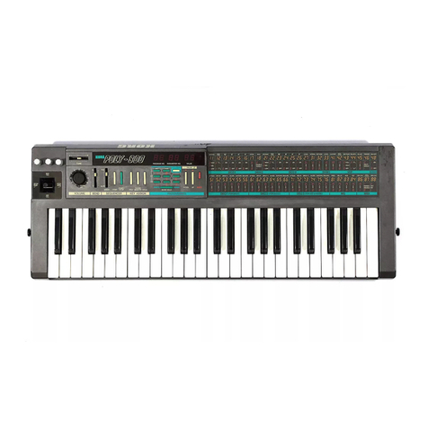
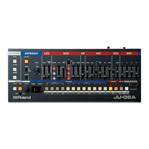
Roland JX-10 User manual

^Roland
mm POL-VPHONIC svnthesizer
SUPER JX
JX-10
Owner's Manual
^Rctend
SUPER JX
IBSBl
no
DE]
Si ^^
IIPIIIPIIIIIIIPPPP

The llghtnlngllash with enowheed symbol, wtthinanequllaiersi
trtengle, is Intended !alen me usee to S\b presence ot un-
insulated "dangerous voltage" within the product's enclosure
that may tie of sufflcisnt masnilude lo constitute ariaK of
el^ric shock lo persons.
The exdamatlon pc^nt within an equHater^ triar;^e Is intended
to alert the user to the preaerK» ol Important operating snti
matnlenancB (»f\rtcing) InstruMcns \n Ihe litefatura taxom-
panying the product.
IINSTRUCTIONS PERTAINING TO ARISK OF FIRE, ELECTRIC SHOCK OR lf4JURY TO PERSONS. |
MPORTANT SAFETY INSTRUCTIONS
WARNING When using alectTH: products, ba^c precBu-
ttons should always be Idlowed, inducing
the following;
1
.
Read aH the mstructlons before using the product.
2. Do not use this product near water- for example,
near abathtub, washbowl, Idtchen smk. in ewet
basmnent, or near a'swimming pod, or the like.
3. Ttils product should be used wily wiih acart or
startt! that is fecommsnded by the manufacture.
4. This prodiK:!, ether abne or in combination with an
amplifier arid headlines or speakers, may be
capable of producing sound levels that could caise
perm^ient hearing kss.
E3o not operate tor along period of tifT» at aNgh
volime level or at level thai Is unccMnfort^le. Kyou
experience any he^ng loss or ringing in me ears,
you stiould consist an aucSologisL
5. TTh product stKRjId be kicaied so that Ite location or
posltlwi does not interfere wHh tB properventHatitm.
6. The product should tte located away from heat
sources such as radiatora, heat reglsiera or other
pmducts that produce heal
7. "Hie product atiould avoid using in wtiere It may be
effected by dust
8. Tba product sfiDUld be connected to apower supply
only of ine type described in the operaUng insinic-
tior^ or as marked on me product
g. The power-s^iply cord ol the pmduct should be
unplugged from the outlet when left unused tor a
long period of lirne.
10. Do not tread wi Iha powef-suppiy cord.
11. Do not pull the cord hut hold the plug when
unplugging.
12. When setting up ksrith any other instruments, the
procedure should tie followed in accordem^ with
instructkm manual.
13. Cere ^lould be taken so that objects do not fall and
liquids are not S|:^lled into me endo^re through
iXienlngE.
14. The proc&jd should be smvlced by qualified SBivice
personnel wtien:
A: The power-supply coitl or itie plug has been
OamBged:Dr
B: Otqeds have fallen, aUquld has been spilled
Into IfiQ product; or
C: The product has been exposed to rain; or
D: The product does not appear to operate
nwtnaliy ot- extiitils amarked ctiange In pertor-
mancaior
E: TYie product has been dn^ped, or me enclosure
damaged.
15. Do not attempt to service the product beyond met
described in the user-maintenarx^e instructions. All
other servicing should be referred to quBllfled service
personnel.
SAVE THESE INSTRUCTIONS
ADVARSEL!
UthiiflrtHttffi. Ekst^osionsfare.
Udskjftrung mS kun foraUges af &[ sa^yndg,
og som beskrevet iservicemanual.
YARNING !
Uthii^batt^. Explosionsrisk.
Far endast bytas av behoig servicet^ker.
Se instmk^oiw iservii^namjabi
ADVARSEL!
Uthlumbatteri. Fare for ^plotion,
Mabare skiftes av kvaiifisert teknlks' som
beskrevet Is^cemanualsi.
VAROITUS !
UthiiiTtparisto. Rajahdysvaara.
Pariston saa vaihtaa ainoastaan
aian ammottimies.
WARNING
THIS APPARATUS MUST BE EARTH GROUNDED.
The three conductors of the mains
lead attacheci lo this apparatus are
identified with color as shown In the
table below, together with the
matching terminal on the UK type
power plug. When connecting the
mains iaad to a plug, be sure to
connect each conductor to the cor-
rect terminal, as indicated.
"This inatnictfon applies to the
product for Unitad Kingdom."
MAINS lEADS PLUG
Canduclor |Color Mark on tha matchIn gterminal
Live 1Brown Had or letier I
MsuitbI iBluB Black or letter N
Grounding Grasn-
YbIIow
Green, GrsBn-YBllow. letter E
or symbol
Bucheinigung das Hentellen /Importaurs
HlBrmil wird baichdnigl, itiQ dar/dic/dai
RQLAMD PROGRAMMABLE POLYPHONIC SVN-mESIi^R _JX-1D
lljn«. Ttp. auBcwmnvl
in ObercJruiiinmung mil dtn BBSiimmungeri dcr
Amtsfal. Vfg 1046 /1984
funk-antliori lit.
D«t Dautichan Bundespoil wurde Oii invwliBhrbfinBtn di*Ml GtHlBi
inoaiaiBt und dU BBrecMiBunu lur UbetpnJtung dor Serie auf Emhiltuns
[lir BBiltrnrnuneen aingarauml.
Roland Corporation Osaka /Japan^
IH*ri1«Hr'i/l,"Vuu'i
RADIO AND TELEVIStON INTERFERENCE
Iradia-fi*au*iiGV avflVr
I^W lo uH in
Iaqutprqant HccrUnd
nd uiad pnvaflv. (
Iand found id tamiilv wfll am Jlmlia lor Clin fi EBrtilwunB
IDuafiwiB'ia In fiuDun J, ol P«n 1S, of FCC Huivi^ Thna rutn wn
apraiiam rtnanMbtm vtaaetton kgiHW wdi miorfiiiwiEa in midamui itiisilfLkDn,
rJniwlamn will
ItMrir biputiflumui cibkn sna ii
rDM ponr b>h« ar »HO caha.
ThH* d*vt» UndHr '•oui'* HBUind jUnqnaiH VilataH I'D i
InnHHu BiMaidatf alM« irarn voui «v«r, ftn *
hAurtaranca by
Umi. If pu buwlbanaa wlov
Idaalar lor ui^nanGa
ainlarlorBnH Dv Vxa
Tui" IT
Moval
Mo«a I
Plug!
unTil ._
WaprihaDi^nDl
aquEnmaiu tanhar away
itana-pvuiii maHb'ai:
jninflBFwKaa Bm*.
IadfiaraiH otsM man Tha Tw vradia UMI «niai»
rlaiUo or iaiav4Wi aat ara on cncuiia cnnrroUad Of diHartPi timn
^^—.- -r lum,!
Conaldar mBlallinQ rpDlmp lalavtaibn ananiui wiih BQaaial aaUa laU-Jn baiwavn i
broaUraE
\ih* aobnimani i
.Fadaral Zitm-
TV,
HnfcvuaiV' voj nouU conaun,ri>ur oaaUf
HUtUonal hrtaaatKHL '
niHMGiUoni ComnuaMft
;
_
'Him m^oantHy and RavuvB Jtauia-IV I——^^^^^__
Tivia booUai »»*arialUB trw (ha US. aa«ran<nuni PrnnmB OniEa, Waihingian. V^c. JOtta,
Please read the separate volume "MIDI", before reading this owners manual.
Copyright ©1986 by ROLAND CORPORATION
All rights reserved. No part of this publication may be reproduced in
anvform without the written Dermission of ROLAND CORPORATiON.
-^
DC
O
(0
LU
Q
UJ
2
B
«\


The Roland JX-10 is fully programmable 12 voice polyphonic synthesizer,
performance control functions can be stored ready to be used.
Various sounds and
The JX-10 features the memory capacity that
can retain up to 64 different programs (= Patch
Memory) which are the combinations of
sounds and performance control functions.
Any of the Patch Memory can be called just by
pushing appropriate buttons.
The Patch Memory you have written into
memory can be easily edited whennever you
like.
The JX-10 containes the sequencer which can
record and playback what you play on the
keyboard.
Using the Memory Cartridges, it is possible to
expand the memory capacity and to save the
sequencer data.
The 76 key keyboard and MIDI functions make
the JX-10 an excellect mother keyboard.
CONTENTS
EPANEL DESCRIPTION 3
[D CONNECTIONS 6
[D OUTUNE OF THE JX-10 8
SOPERATION 10
1. Selecting aPatch Memory 11
2. Functions of the Control Knobs 12
3. Control Assign 14
4. Quick Editing of Patch Memory 16
a. Key Mode 16
b. Tone Number 18
c. Chase Play 19
5. Sequencer 21
a. Recording Sequencer Data 21
b. Playing the Recorded Data 22
6. Edit 24
a. Editing aPatch Memory 24
b. Editing aTone 31
c. Recalling aTone 40
7. Writing into Memory 41
a. Writing aPatch Memory 41
b. Writing aTone 42
c. Naming 43
d. Writing the Whole Data 46
8. Memory Cartridge 47
a. Copying the Entire Data
(All Patch Memories and 50 Tones) ... 47
b. Copying aPatch Memory 49
c. Copying aTone 51
9. Other Useful Functions 53
a. Tuning 53
b. Function Display 54
c. Error Messages 55
10. MIDI 56
a. Receiving and Transmiting MIDI 57
b. MIDI Functions available for
aPatch Memory 60
[U SPECIFICATIONS 67
IMPORTANT NOTES
•The appropriate power supply for this unit is
shown on its name plate. Please make sure that
the line voltage in your country meets the
requirement.
•Please do not use the same socket used for any
noise generating device (such as motor, variable
lighting system).
•This unit might not work properiy if turned on
immediately after turned off. If this happens,
simply turn it off and turn it on again afew
seconds later.
•Before setting up this unit with other devices,
turn all of them off.
•This unit might generate slight heat while
operating, but there is no need to worry about it.
•Use asoft cloth and clean only with amild
detergent.
•Do not use solvents such as paint thinner.
•Avoid using this unit in excessive heat or
humidity or where it may be affected by direct
sunlight or dust.
•Save the necessary data on acartridge or make
data memo before having the JX-10 repaired, in
case it should happen to be accidentally erased.
•Before connecting or disconnecting the car-
tridge, be sure to set the Protect Switch to the
On position. To prevent the accidental loss of
the data, never move the Protect Switch to the
Off position, unless it is specifically instructed in
the manual.
1mm
asT-w
Protect Switch

z\ CONNECTIONS
@
f^-tna HiatiCT
nn "afe a; ."• nn
Programmer
PG-aoo MiDi
Device Mixer
Amplifier
?sK! WM Pedal Switch DP-B
or DP-2
Expression Pedal
EV-5
TU Amp.
®
Headphones
Example Setups
Ip,
tOC
©^ ooo oy ppoooooi
L_J LJ
oo o a
®
CI! oo o ^5* ^9000000 ct)
o
Oo
O

1. Total Mix Output Jack ®3. Output Level Switch
Connect this to the ampiifter. To make the best use
of the JX-1 0, use the amplifier and speaker of wide
frequency response and dynamic range such as
keyboard ampiifter.
2. Parallel Output Jacks ®
These are also for connecting amplifiers. Different
ways of connections will make various sound
effects.
The following shows several different ways for
using the Output Jacks.
PARALLB. OUTPUT
tuoMx Huuen
(7)©©(^©
Connection Jack Output Power
Uack EMonaural Output
2Jacks ADMixed Output of Upper
and Lower
BCB: Monaural Output of
Upper
C: Monaural Output of
Lower
ABStereo Output of Upper
C D Stereo Output of Lower
4Jacks AB
C D Stereo Output of Upper
and Lower
When the JX-10 is set to the Whole mode,
connecting astereo amplifier to the UPPER
MONO and LOWER MONO of the Parallel Out-
put Jacks 26 (output jacks Cand Dshown in
the above picture) will cause the sounds to be
output irregularly through Lor R. It is normal
for this unit to behave like this.
Use this switch to select the output level depend-
ing on the amplifier connected to the Total Mix
Output.
*This switch does not work on the signal sent
from the Parallel Output Jack.
4. Headphones Jack ®
Connect stereo headphones to this jack.
5. Hold Pedal Jack ®
By connecting the optional pedal switch DP-6 or
DP-2, the Hold effect can be turned on or off by
pressing the pedal. "Hold" is the effect of keeping
the sound even after the key is released.
6. MIDI Connector ®
This is for connecting to other MIDI device using
the MIDI/SYNC cable (optionalj.
7. Programmer Connector
Connect this to the programmer PG-SQO (optional)
using the supplied 6P DIN cord.
8. Protect Switch ®
Always make sure that this switch is set to the ON
position to protect the data in the JX-10, except
when saving or loading data.
9. Control Assign Jack ®
Use this jack when assigning the Control Changes
with the expression pedal or pedal switch.

¥\ OUTLINE OF THE JX-10
The JX-10 features the functions that are quite
different from those of the past synthesizers.
So, it is very important to understand the func-
tions. Read the following explanation, then go to
"B OPERATION".
1. The JX-10 retaines 100 different sounds
{Tones} -50 of them can be rewritten, other 50
non-volatile -and more, the 64 combinations
of the Tones and various performance control
functions (this combiantion is called Patch
Memory). That is, aPatch Memory consists of a
Tone or apair of Tones and performance control
functions which we call Factors in this manual.
Normally, to change sounds during live perfor-
mance, select adifferent Patch Memory.
(See page 11 "1. Selecting aPatch Memory".)
2. The Factors of the Patch Memory can be edited
easily whennever you want.
(See page 24 "a. Editing aPatch Memory".)
3. "Die Tone of a Patch Memory can be edited just
like you would do on ausual synthesizer, A
tone consists of various parameters, and atone
is edited by changing these parameters.
(See page 31 "b. Editing a Tone".)
4. To write the edited Patch Memory into the
JX-10's memory, take an appropriate writing
procedure.
(See "a. Writing aPatch Memory" on page 41.)
(See "b. Writing aTone" on page 42.)
5. By using the supplied Memory Cartridge
{M-64C}, the foilowing data transfer is possible.
a. Saving each Patch Memory or Tone to the
memory cartridge and loading it back to the
JX-10.
b. Saving the entire data (50 Tones and 64
Patch Memories) on the JX-10 to Ihe memory
cartridge and loading it back to the JX-10.
6. The sequencer data can be saved on the
supplied Memory Cartridge {M-16C). By using
one more Memory Cartridge M-64C which is
optional, you can save the data four times more.
(See page 21 "5. Sequencer".)
7. All the Patch Memories and Tones have their
own names which can be changed as you like.
(See page 43 "c. Naming".)
8. The JX-10 features the MIDI functions neces-
sary for operating or being operated with other
MIDI devices. The MIDI functions can be
changed according to your requirement.
(See page 56 "10. MIDI".}
9. To make the above operations quicker and
easier, the JX-10 has adisplay window. If the
operation is wrong, the Display will respond
with error messages.
(See page 55 "c. Error Message".)
(See page 47 "8. Memory Cartridge.)

1t
E—
en
aU.
ill
•S
=: F
x: F
51— tn
O! n
V
LU
Q. Fs-
3o0.
LU s
H-i<: ut
a• •
H^^^"^^
c
^5 E-s
S3:
w^ s
,_
t
1
1,_
cUJ Li
c
Li-
gS
0) ,in
31en
^£r g^£
--'
o
£-n ~
.E o^
5Ed
>R3
u
trt S]
«. IJ o
ii D- g
U9
m
a>
m
(A
U5
01
c
o
Tj
if ^
.2
1
2B^
O.= .:=
2UJ g

T] OPERATION
Set up the JX-10 with the externa! devices such as
ampiifier and speaker, then switch it on, and the
JX-10 is ready to be played with any of the 64
Patch Mennories.
APatch IVlemory is made of one or apair of the
100 different Tones and various performance con-
trol functions such as Split Point, Bender Sensitiv-
ity, etc.
100 Tones
51 to 100: Preset
1to 50 :Internal Memory
39
Performance
Control
Function
Patch Memory
A-1 Patch Memory
A-2
Ir
\1
t1
1i
~1
1Patch Memory
H-8
J
64 Patch Memories {A-1 to H-8)
10

1. Selecting aPatch
Memory
Make sure that the connections are made securely
and correctly, then switch the JX-10 on.
The Display will show "ROLAND JX-10" for several
seconds, then change to as below.
T_ O
J. 'I
Vi X1^
rtV /ft /IN Vi X^
/ft n\ fl\
The 64 Patch Memories are stored either in
the JX-10's internal memory or on the
Memory Cartridge (M-B4C). The display
here shows whether the Patch Memory
currently selected is in the JX-10 or on the
Cartridge.
Internal Memory of the JX~10
The 64 Patch Memories are stored in the
locations of 8Banks (1 to 8) and the Num-
bers (1 to 8). The display here shows the
Bank and the Number of the Patch Memory.
C:Each Patch Memory can be named with up
to 18 characters (this is called Patch Name.)
Here, the patch name is displayed.
D, E:The numbers 1to 100 are assinged to the
100 Tones in the JX-1 0's memory. The num-
Ibers of the Tones used for the Patch Mem-
ory currently selected are displayed here.
The Tone number of the lower section of
the keyboard is shown at Dand that of the
upper section is shown at E.
*What are shown at A(Memory Mode) and at B
(Bank and Number of the Patch Memory} are
always displayed there except for In the Writing
(see page 41.) and Master Tuning (see page 53.)
modes.
To select aPatch Memory, assign the Bank and
Number by using the Patch Memory Buttons®.
*The JX-10 is designed to produce no sound
while you are changing Patch Memories. This
serves to mute the noise which otherAwise would
be heard. If you do not like cutting sound,
instead of changing Patch Memories, change
the Tones (See page 18 "Selecting aTone
Number"). In this way, you can call the sound
you like without any silence at all.
Example
Push B -» 3<> 11-33
Push 6c^ [l-'BS
Push GO!l--G5
11

2. Functions of the Control
Knobs
The following controls can be operated even while
you are piaying the JX-10.
a. Control Assign Knob &
Each of these two knobs can be used for control-
ling the performance control function you select
with the Control Assign Button. (See page 14 "3.
Control Assign".)
b. Bender Lever O
This Bender Lever can be used during live perfor-
mance for creating guitar's chocking-Hke effect.
The left and right extremes of movement create
the same amount of pitch bending effect. The
maximum effect of the bender can be selected
with the Bend Range Switch: major 2nd, minor
3rd, major 3rd or perfect 5th higher or lower.
Pushing this lever forward will create the vibrato
effect. When the tone you are using has already
taken in avibrato effect, the effect will be deepened.
c. Aftertouch Rne Adjust Knob O
The Aftertouch effect is the sound's alteration
obtained by pressing the key stronger after playing
it in anormal manner. The JX-10's aftertouch
effect works on the Vibrato, Brilliance and Volume.
Vibrato: The dpeth of the vibrato effect is
deepened.
Brilliance; The tone will become brighter.
Volume: The volume of the sound will increase.
O
©
n
'=—^—
==;
==L
3- =
=3r
The setting of On/Off or value of each aftertouch
effect can be written in each Patch Memory inde-
pendently, but the Aftertouch Fine Adjust Knob
allows even more delicate adjustment of the
effect When this knob is set to the center position,
the same effect as set in the Patch Memory can be
obtained, and no effect is obtained at the lowest
position [— ].
*Different On/Off settings and values of the after-
touch and bender are written in each of the 64
Patch Memories. Therefore, those effects you
acturatly gain will greatly differ depending on
how these are set in the Patch Memories. No
effect may be obtained in some particular
settings.
12

d. Voice Memory Switch @
This switch selects which memory mode; the JX-
10's interna! memory or the Cartridge memory to
be used.
a
CART INT
Patch
Memory You can call aPatch
Memory in the Cartridge You can call aPatch
Memory in the JX-10
Tone
Tone Numbers 1to 50 =
Tones in the Cartridge Tone Number 1to 50 =
Tones in the JX-10
Tone Number 51 to TOO =Tones in the JX-10
*Even after you have changed the Memory
modes with the Voice Memory Switch, the new
position does not affect the memory unless you
select anew Patch Memory.
When you select anew Patch Memory, "I"
(internal) or "C"(cartridge) is shown at the left
end of the Display, depending on which position
has been selected with the Voice Memory
Switch.
*When the Memory Cartridge is not connected,
be sure to set the Voice Memory Switch to the
INT position.
13

3. Control Assign
The JX-10 allows you to control some of the per-
formance control functions with the Control
Assign Knobs on the control panel and the Pedal
Switch {DP-6 or DP-2). This is exeilent in live per-
formance. However, the functions which can be
controlled are only two of the four with the two
Control Assign Konbs and one of the four by the
pedal switch at atime. (See the table shown on
the next page!. The following explaines how to
assign the functions to the i<nobs and the pedal
switch. The function assigned to each knob is con-
trolled by moving the slider, and the function
assigned to the pedal switch is controlled with the
pedal operation. We call these eight functions
Control Assign functions.
PROCEDURE
CD Select the Control Assign Knob 1, 2or Pedal
Switch where you wish to assign the function
by pushing the appropriate Control Assign
Button; CI, C2 or PEDAL SWITCH Button.
EDED
The Display will show the Control Assign function
that is previously assigned.
©Rotating the aDial, call the new function to
be assigned. (See the table shown on the next
page.}
@To continue to assign other functions, repeat
the step ®and @.
®When you have completed assigning all the
Control Assign functions, push the Control
Assign Button currently in use.
The Display will return to the usual indication.
While the Display shows Control Assign function,
nothing can be done on the JX-10 except for play-
ing the keyboard.
When the Expression Pedal EV-5 is connected to
the Control Assign Jack on the rear panel, the
assigned Control Assign function cannot be con-
trolled with the Control Assign Knob but only with
the pedal.
•Writing the Contro! Assign
The Control Assign functions you have set can be written
into the JX-TO's internal memory as follows.
After stepCs), set the Protect Switch ®on the JX-10 to
the OFF position, then push the WRITE Button ®.
I(OTTT)~ft( rntKiTnni
The Display will respond with as above, then return to
the usual indication.
14

When CI or C2 is selected, any of the foHowing four functions can be assigned.
W1
,-
C1 C2 'Ch of lD or is pushed,
shows the value set in the Patch Memon/.
Display Description
Adjusts the volume balance of the Upper
and Lower.
Raising the Knob increases the Upper
volume, and iowering the Knob increases
the Lower volume.
L. 'l_l_JJ.U' «1*1 1 '1 "OOt
) ' U' t_ J.1I II— 1^^
(Upper/Lower Balance
Adjusts the Portamento Time.
Raising the Knob makes longer Por-
tamento Time.
1" .-ir rrrn il_l 'l_'l^ ill. /±1ll_ fjf
(Portamento Time}
Adjusts the volume within the range of
the maximum volume set with the Master
Volume. Raising the Knob raises the
volume, reaching the maximum volume.
At the same time, the MIDI volume of the
Upper and the Lower change.
no TO TO' 1't~ll
ILJ 1U1III— Vl-}l— ?fj^
(Total Volume)
-
Controls the MIDI messages of the Upper
or Lower section.
Refer to "MIDI" on page 56.
re 1lO H4TTiTi'Oi
U-J Ul 1tx XIX *LJl- £Jf
r.DC rTrri" f~ C1O^l! T"n T(fOl
Ol-I l_LJ 1fJ. XIX" U'_ If in
(MIDI Volume)
*When PEDAL SWITCH is selected, any of the following four functions can be assigned.
PEDAL
SWITCH
Display Description
Pressing the pedal changes the bank and
the number of the Patch Memory.
A1 -* A2 A8 ^B1 ^82
11 1 11^1 \_(i 1X1 1
(Patch Shift}
Turns the Portamento ON or OFF.
1„i ''_i_iXU'^ JUl •1rM((_! "1LJ
(Portamento ON/OFF}
Turns the Chase Play Function (p. 19)
ON or OFF.
ni~ oi-cTC" 1
1_i '1_i_'X O'" \_l II 1JIL, JU' 11
(Chase Play ON/OFF)
Turns on or off the Hold Effect of the
Upper and/or the Lower section.
or o"rTrM
'_i 11—1 _IX(_II w1'ODCO i-Tli Ti
i—ii<i—i- 'lUt- XI
i~, r- or- rTI" i> I
J—\ 1I_t _l Xi_it "1oi ir n1(Oi Ti
(_ i_it"i'_ 1f'lU'u XI
(Upper Hold, Lower Hold}
15

4. Quick Edit of aPatch
IVIemory
The following three Factors can be quickly edited
even during live performance just by touching the
relevant button.
•Key Mode Select: Whole (Upper, Lower),
Dual and Split
•Tone Number: Tone(s) in aPatch Memory
•Chase Play: When the Key Mode is Dual,
delay-iike effect can be
obtained
*The above editing function does not automati-
cally rewrites the data in memory unless you
take the appropriate writing procedure explained
on page 46. Therefore, selecting anew Patch
Memory will erase the edited data.
a. Key Mode
There are following 6Key Modes
1. UP WHOLE (Upper Whole)
2. LO WHOLE (Lower Whole)
3. DUAL
4. SPLIT
5. T. VOICE (Touch Voice)
6. X-FADE (Cross Fade)
1to 4Key Modes can be called with Quick Edit. 5
to 6Key Modes can be set just when editing the
Patch Memory.
The three Key Mode Buttons are used for setting
the Key Mode. The indicator of the pushed button
will light up.
C3 IIZ3
DUu. »n.tt
16

split Mode Whole Mode
This mode divides the keyboard of the JX-10 into
the upper and the lower sections where two diffe-
rent Tones can be used. That is, the JX-10 works
just like two sets of 6voice synthesizers of diffe-
rent sounds.
The JX-TO's unique Split system allows to set the
lowest key in the Upper section and the highest
key of the Lower section separately on the same
keyboard. The Quick Edit, however, does not
include this function. This is possible only when
editing aPatch Memory.
PROCEDURE
in this mode, the JX-10 can be used as ausual 12
voice polyphonic synthesizer. That is, all the 76
keys will have the same Tone. Therefore, it is
required to select one of the two different Tones
provided for the upper and the lower sections.
When the Tone for the upper section is selected, it
is called Upper Whole Mode, and when the lower
Tone is selected, called Lower Whole. Pressing
the Whole Button will alternately select the Lower
and Upper Tones.
The Display shows the Tone Number currently
selected.
While holding the SPLIT of the Key Mode Button
down, press the key which is to be the Split Point.
While holding this
button down.
Dual Mode
The Dual Mode turns the JX-10 to the 6voice
synthesizer that allows both the Upper and the
Lower Tones to sound simultaneously. Arich
sound is obtained.
There are two independent pareiiel outputs for the
upper and lower Tones, which serve to create the
effect as if two synthesizers were simultaneously
played.
Push the Key where the keyboard should be
divided into two sections. Upper and Lower.
The right side including the pushed key will be
the Upper, and the left will be the Lower
keyboard.
17

b. Tone Number
To change the Tones in aPatch Memory, simply
assign the Tone Number of the relevant Tone by
using the Ten Keys.
PROCEDURE
(T) Push the Upper or the Lower Button ®to
select the Upper or Lower Tone which you
wish to change.
@Pushing the appropriate Ten Keys, assign the
new Tone Number, then hit the Enter Key.
Tone Numbers of the
Patch Memory currentiy
selected are displayed
Select the
Upper or
Lower Section
,Assign the Tone Number
you want by using the
Ten Keys
iC. 11 T
Adot is shown at the
right to the Lower
Tone Number
E1DDU The Tone Number of the
Upper Section changes
1- ii -1
(C. D1
The Tone Number of the
Lower Section changes
DC DU
Lf^f\ 6
"0" of the Ten Keys can be used instead of the UPPER and LOWER Buttons.
Even when using the Patch Memory of the JX-10's
internal memory, the Tone Number of the Car-
tridge can be called.
After taking the step (V), change the Voice Memory
Switch to the CART position.
Then return It to the INT position after taking
the step (2).
If you call other Patch Memory without writing it
into memory, the Tone called from the Cartridge
memory will be erased.
To call the Tone from the Memory Cartridge (M-
16C), take exactly the same procedure as above.
The available Tone Numbers, however, are from
1to 32.
18

c. Chase Play
The Chase Play function makes it possible to out-
put the Lower sound slightly later than the Upper
sound. This function, however, is available just in
the Dual Mode.
Depending on the delaying time and the Tone in
use, the effects created differ; delay-like effect,
sound-on-sound like effect etc.
PROCEDURE
Push ON/OFF of the Chase Play Buttons ®.
The corresponding indicator wili light up, showing
that now the Chase Play function is turned on.
(2) Set the following 3functions: Time, Level and
Mode so that the ..'^isired effect will be obtained.
The "Level" and "Mode" are alternately selected
by pressing the FUNCTION of the Chase Play But-
tons. The Display shows the function selected.
The "Time" function can be selected by pressing
the TIME of the Chase Piay Buttons. The value of
the selected function can be changed by using the
QDial.
1) Level
This sets the level of the delayed sound (= lower
sound).
Rotating the aDial, set the value you like. The
value changes from 00 to 99, and the higher
number sets higher level.
Drurinjtc. run Ii^czu tit. k^
Jfi^: 00 to 99
19

2) Mode
This sets how the delayed sounds are output
sequencially. As you rotate the aDiai, the Display
changes as "U-UU-", "U-L-L-" or "U-L".
•U-L-U-: in this mode, Upper sound is output
first, then Lower, Upper, Lower
repeatedly.
•U-L-L-: in this mode. Upper sound is output
first, then Lower sounds repeatedly.
•U-L: in this mode. Upper sound is first
output then Lower. No more sound is
output.
1
—
1
_tL_ ntnrr
(_i ni_n_ hAfmr
1IL_(XI(_ ^^^^^ ^
ir\ n\ tri iT\ il\ if\
Ii!fJf««J!f-. u-L-U-
U-L-L-
U-L
Tiiree Modes
3) Time
This sets the time between the first (Upper) sound
and the second (Lower) sound.
Push the TIME of the Chase Play Buttons to turn to
the Time adjusting mode, then change the value
rotating the aDial. 01 to 99 are valid and the
higher number is longer time.
c1ruo^c:
_J_.t (_nf r_iu
As the ievel described on the previous page in
"D Level" is set higher and the key touch is
stronger, more delay sounds are obtained. If the
Tone Parameter Number 63 "VGA Dynamics
Range" is set to OFF, the volume of the sound
does not change, but repeats in the same volume.
IL-' MI±1 l(_ ^^
S^- 01 to 99
When you have completed editing all the func-
tions, hit the Enter Key.
20
Other manuals for JX-10
5
Table of contents
Other Roland Synthesizer manuals

Roland
Roland Lucina AX-09 Assembly instructions

Roland
Roland SH-101 User manual

Roland
Roland JUPITER 8 User manual

Roland
Roland SH-101 User manual

Roland
Roland VR-700 Instruction manual

Roland
Roland D-05 User manual

Roland
Roland U-220 Operating and maintenance manual

Roland
Roland XV-2020 User manual

Roland
Roland PG-800 User manual

Roland
Roland RS-50 Technical manual

Roland
Roland SH-1000 User manual

Roland
Roland XV-5080. User manual

Roland
Roland Jupiter-Xm User manual

Roland
Roland E-09 User manual

Roland
Roland CG-8 User manual

Roland
Roland GW-7 User manual

Roland
Roland SH-09 User manual

Roland
Roland XV-5080. User manual

Roland
Roland CG-8 Operator's manual

Roland
Roland SH-4d User manual