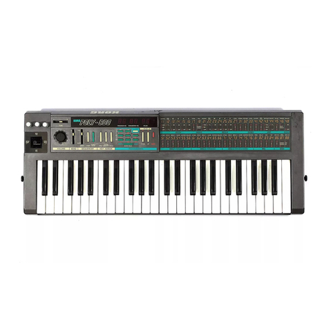
SH-101 NOV. 1st, 1982
ADJUSTMENT PROCEDURES
Precautions:
The order of the adjustment procedures in these adjustment specifications
were determined assuming that the SH-101 unit has not been adjusted at all.
Therefore, when only afew sections are to be adjusted, please keep the
following points in mind.
When adjusting the VCO Width, VCO Tune, and/or VCF, be sure that the
D/A Converter adjustment has first been completed. (This is because D/A
Converter failure may affect these circuits.)
Because the VCO Width and the VCO Tune interact with each other, be
sure to perform both adjustments.
2. VCO ADJUSTMENT
Preparations:
•If the unit is in the Test mode, release the mode by either pressing the
HOLD button or resetting the Power Switch to On.
Set the panel controls as shown in Fig. 1
.
Connect the oscilloscope to SH-101 OUTPUT. Supply the reference F
note (based on A=442Hz) to the scope EXT. Input for the Lissajous
figure.
(D) Pulse Width
1. Set the WAVEFORM to [~U .
2. Adjust VR-2 (D/A TUNE )until the mark/space ratio is 1:
1
3. VCF ADJUSTMENT
Preparations:
Set the panel controls as shown in Fig. 2.
Connect the oscilloscope to the SH-101 OUTPUT.
ii
ii
ii
i'
i
I
i
I
i
I
I
i
I
1
I
'I
I
I2'
4'
8'
»-* 16'
16' (Key Transpose Function)
16' (Sub Oscillator 1Oct. Down) I"
(Key Transpose function)
2'
Transpose LMiddle C
ITYMnipose H
i i
OV 1V 2V
F3
,III
II3V I|4V
F4A4 F5A5
i
i
i
i
i
Piano Keyboard
5V
Keyboard of the SH-101
When the VCO Range is set
to 8' and the Transpose
switch to MIDDLE, A4
corresponds to 442Hz.
TUNC
I1
VOl UMl
•CO
rIFO
<P MOO
'—
T'-
MODULATOR
1*0 dK
«ATl CT WAV* 'OHM
VCO SOURCE MIXER VCF VCA
n
v.
-"V 'U
MOO
1RAMGt PVkSC WOTK ISU6 0SC HOtSC
«
J
FRtO RtS ENV WOO xrno
nn?*n
,
u—2 I-
u
-fi, H
:tir
JU
I-.
_j
•i
stout NCI
«
.(CO IIHWOU
PORTAUCNT
-«• •
i
JLi UM>N**?1(
•CNDC"
cr a
•ENOCH
.-B
Fig. 1
CD
POW£«
VOLUMt
MODULATOR
LKVCUt
?UNC RATC CD WAVE FORM MOO
VCO
RANG* PULS£WC»TH nj
SOURCE MIXER VCF
nj si
~
oj r
10 i
4
3...n
»•-
n
u=-
J
NOSE F*£0 RES EHv MOO KVBO
J
VCA
n
j
CD r-i CD
IB QO C3 Q
*ou«»c*» LSI
PO«TAMfNT
I
9CNOER Fig. 2
w
.
1. D/A CONVERTER ADJUSTMENT
Preparations:
Connect the digital voltmeter (with more than 4significant digits) to the
CV OUT jack.
While pressing both the LOAD button and the KEY TRANSPOSE
button on the SH-101 unit, turn the Power Switch On. (The SH-101 unit
is now in the Test mode.)
(A) D/A Tune
1. Confirm that the LOAD and TRANSPOSE LEDs areilluminated.
If any of the LEDs other than the LOAD LED is illuminated, press the
LOAD button.
2. Adjust VR-2 (D/A TUNE) on the Synth. Circuit Board until the digital
voltmeter readsOV ±1mV.
(B) D/A Width (+5V)
1
.
Press the PLAY button.
2. Adjust VR-1 (+5V) on the Synth. Circuit Board until the digital volt-
meter reads 2.75V ±1mV.
(C) D/A Linearity
1
.
Press the ARPEGGIO DOWN button.
2. Adjust VR-3 (D/A LINEAR) on the Synth. Circuit Board until the digital
voltmeter reads 2.5V ±1mV.
(D) Repeat the above procedures (A) through (C) until all the voltage read-
ings are within ±1 mV of the specifications.
Note:
To compensate for the variations of the components, the VCO Tune
Circuit is designed so that a+15V voltage can be supplied or inhibited.
(The position is shown in the circuitdiagram with the imark.)
If the adjustment cannot be properly performed by adjusting VR-7,
short-circuit the break in the pattern on the back of resistor R102. If it is
already bridged or wired, open it.
(A) VCO Width
1. Hold the F5 key down, and adjust either VR-7 (VCO TUNE) or VR-9
(TUNE) until the Lissajous figure is motionless.
2. Hold the F3 key down, and adjust VR-6 (VCO WIDTH) until the figure
is again motionless.
The F5 pitch will vary as VR-6 (VCO WIDTH) is turned.
3. Repeat steps 1and 2until the F3 and F5 figures are motionless.
(B) VCO Tune
1. Place the unit in the Test mode. (While pressing both the LOAD button
and the KEY TRANSPOSE button. turn the Power Switch On.)
2. Press the U&Dbutton.
3. Confirm that VR-9 (TUNE) issetin- the center position.
4. Adjust VR-7 (VCO TUNE) until the output value is 442Hz.
(C) Range Width
1. Place the unit in the Test mode
2. Press the U&Dbutton.
3. Press the UP button, and adjustVR-5 (RANGE WIDTH) until the output
pitch is the same as the outputpitch in the U&D mode.
1. Hold the A4 key down, and set the CUTOFF FREQ. for approximately
1kHz.
2. Alternately, play the F4 and F5 keys, and adjust VR-8 (VCF WIDTH)
until the F5 figure cycle is twicethe F4 cycle.
4. LFO MOD OFFSET
Preparation:
•Connect the digital volt-
meter to test points TP-1
and TP-2 on the Bender
Circuit Board as shown in
Fig.3.
1. Adjust VR-3 (D/A LINE-
AR) until the voltmeter
reads 0+ 2mV
Note:
The adjustment can be per-
formed from the direction
of the foil pattern.
so
rnv
in
*^-
v«v
—
*»sn *hoi _
—«wen
so
ra
T
J^P
BOI
n
eo
£2 r>
>
O
Ooj nj
aflv
m
it
o
o
CD
o
o
Xr
TP-2
0£ as
i
aflv *flV
,'r'
c=d V^'o Fig. 3
J
4
