Roline ATS User manual

ATS User Manual
1
ATS USER MANUAL
ATS (Automatic Transfer Switch) User Manual
19.07.3415

ATS User Manual
2
Content
I ATS Overview ............................................................................................................................................... 4
II Function Description .................................................................................................................................... 4
III Application ............................................................................................................................................... 5
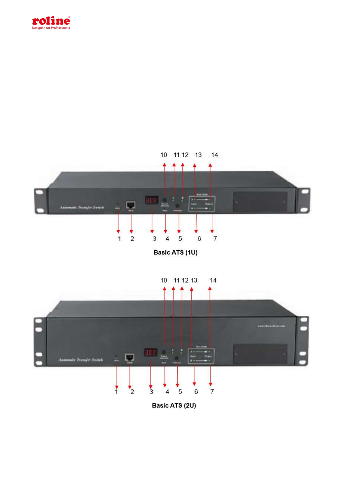
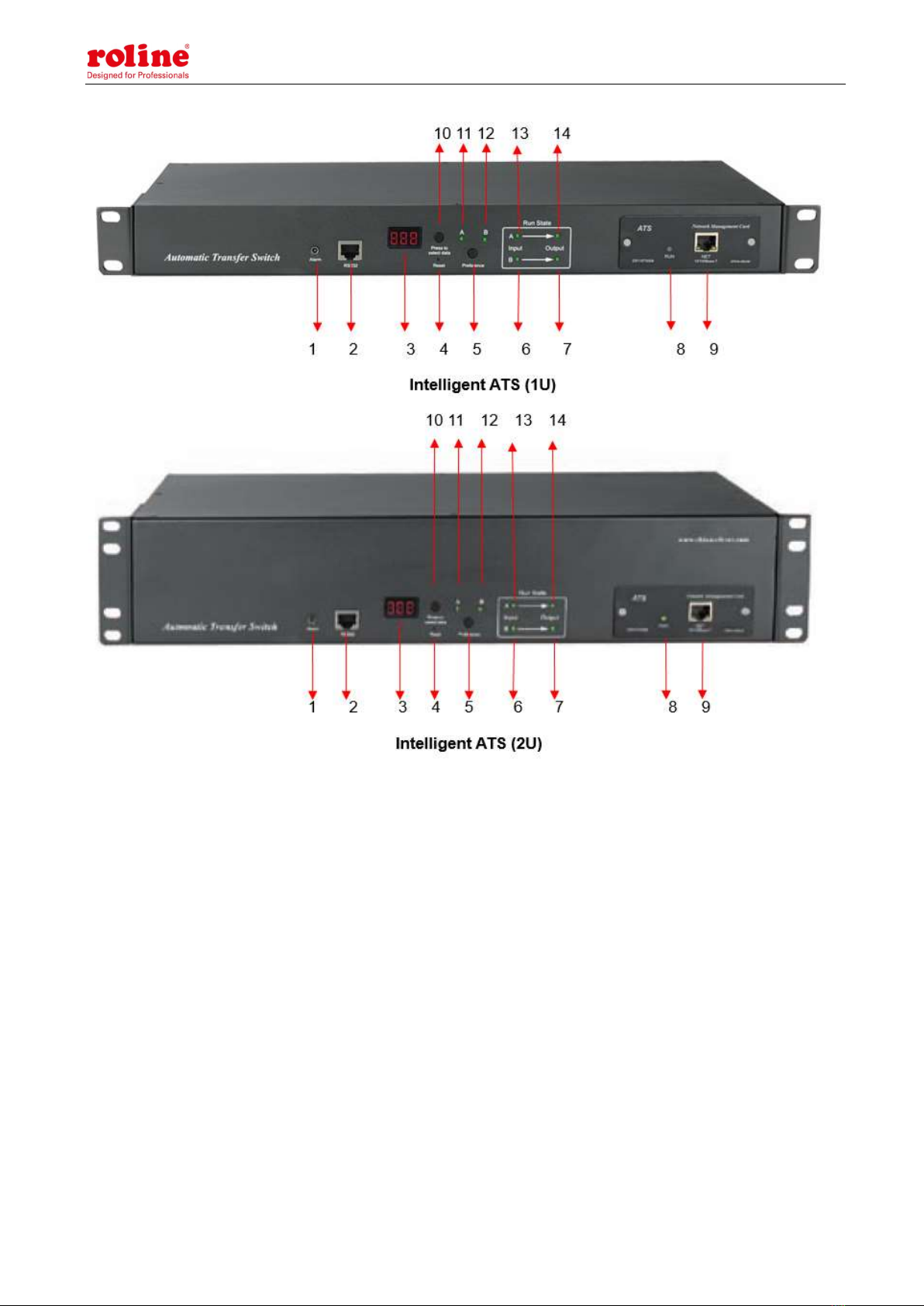
IV Product Schematic ........................................................................................................................................ 5
V Installation ..................................................................................................................................................... 7
VI Hardware Introduction ................................................................................................................................ 7
1. Power on self check..................................................................................................................................... 7
2. Operation status viewing............................................................................................................................ 7
3. Select the preferred power source ............................................................................................................. 7
4. Reset operation ........................................................................................................................................... 7
5. Restore to factory settings .......................................................................................................................... 7
6. Serial connection ......................................................................................................................................... 7
7. External audible and visual alarm ............................................................................................................ 8
8. Network connection(only intelligent type) ................................................................................................ 8
9. Intelligent ATS firmware upgrade ............................................................................................................ 8
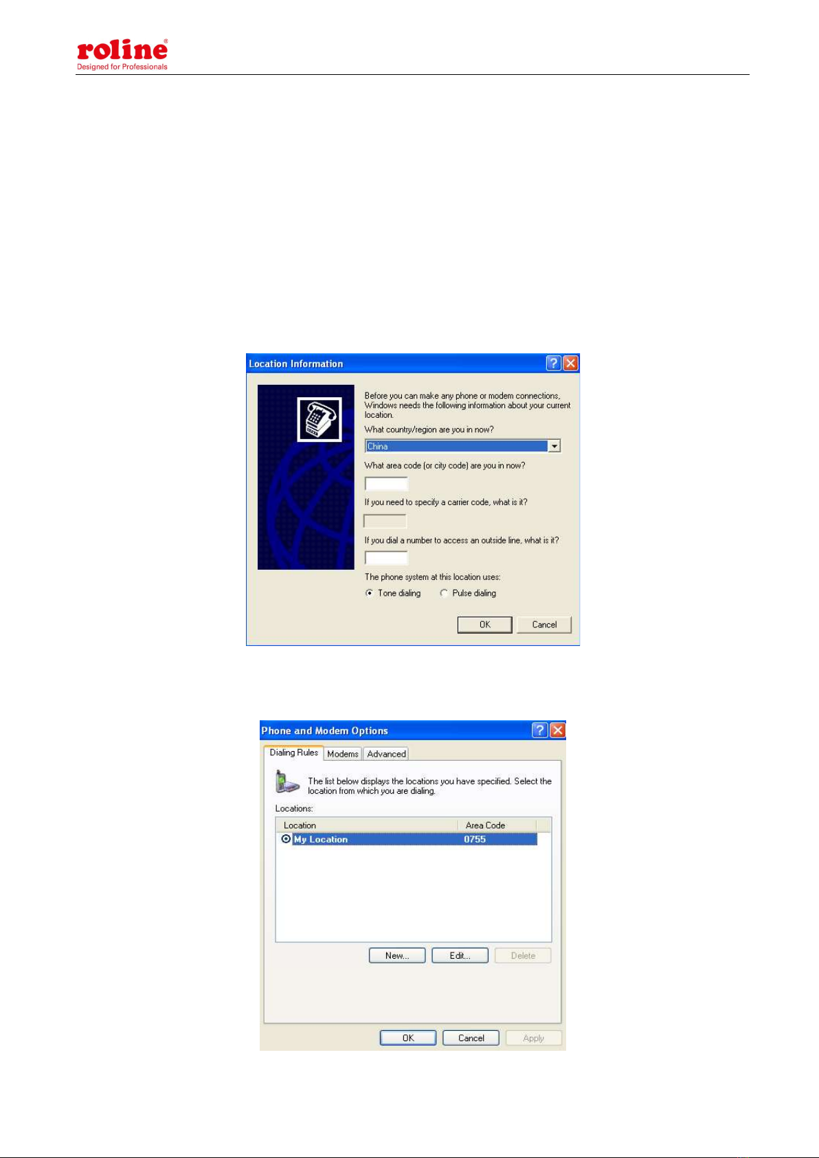
VII Hyper Terminal user guide ................................................................................................................... 10
VIII Software user guide ............................................................................................................................... 19
1. Software Introduction .............................................................................................................................. 19
2. Software configuration ............................................................................................................................. 20
2.1. Device default settings ............................................................................................................................. 20
2.2. Device configuration when first log in.................................................................................................... 20
3. Access method ........................................................................................................................................... 21
3.1.1 Device Status ............................................................................................................................. 22
3.1.2 Device Config ............................................................................................................................. 23
3.1.3 Threshold Setting ...................................................................................................................... 23
3.1.4 Event logs ................................................................................................................................... 24
3.1.5 User Management ..................................................................................................................... 26
3.1.6 Network Config ......................................................................................................................... 27
3.1.7 HTTP/SMTP ............................................................................................................................. 27
3.1.8 SNMP/Telnet.............................................................................................................................. 29
3.1.9 Restart ........................................................................................................................................ 30

ATS User Manual
3
3.1 SNMP ......................................................................................................................................... 30
3.2 Telnet access............................................................................................................................... 32
IX Performance parameters ............................................................................................................................ 33
X Quality guarantee ....................................................................................................................................... 34

ATS User Manual
4
I ATS Overview
Automatic Transfer Switch; ATS for short;
Automatic Transfer Switch is a high reliable switch that provides redundant power to connected
equipments. If the primary power source becomes unavailable, the ATS will seamlessly switch to the
secondary power source automatically. ATS are divided to basic and intelligent two types, user can
upgrade the basic ATS to an intelligent one easily by inserting a hot-swappable Network Management
Card, which enable user to monitor and manage the ATS with web interface or SNMP platform.
II Function Description
1. Switching: Switch over between Source A and Source B automatically, transfer time 10~16ms
2. Monitoring: total load current; input and output voltage;
Source A and Source B power input; ATS operation status
3. Remote controlling: switch over between Source A and Source B
Set the threshold for the total load current and input voltage
4. Automatic alarming: automatically alarm when threshold is exceeded
5. System default alarming: When total load current/voltage exceed the threshold
When there is only one power source available
When automatical switching occur
6. Alarming method: Buzzer beeping and display flashing
E-mail alarming (only intelligent type)
7. Log recording: record and save the log of the device running and alarming information
User can view and export the logs
8. System support: support single user only, support remote firmware upgrade (intelligent type only)
9. User management: set the authorization of the account. User create, modify, delete operation.
10. Access method: Ethernet connection, web interface through IE browser
SNMP(V1/V2c/V3), access and control through standard simple network management protocol
Serial Connection RS232 (Hyper-terminal Protocol by defaulted)
11. System setting: system time setting.
Lock controller panel
Voltage/current threshold setting
Automatic reverse-switch time setting.

ATS User Manual
5
Buzzer switch setting;
III Application
1. ATS products are applicable for all kinds of server racks and network cabinets.
2. ATS products are in accordance with the regulation of RoHS.
IV Product Schematic

ATS User Manual
6

ATS User Manual
7
V Installation
Horizontal rack mounting
VI Hardware Introduction
1. Power on self check
The buzzer beeps once when power is on, the LED indicator is always on, digital screen display
load current after self-checking
2. Operation status viewing
Through "press to select data" button, user can view the voltage; IP address (only intelligent type) ,
device version number and load current.
3. Select the preferred power source
Use “Preference” button to select the primary power source, three options user can have: set the
source A as the preferred power source; set the source B as the preferred power source; or user can
leave this open. The corresponding indicator will always light on if a choice was made. If not, the two
indicators will stay the off status. Please be noted that the intelligent ATS has the Lock function, if
user can not do the setting above, it is probably because the controller panel is locked in the
firmware and please log on to the Web interface to unlock.
4. Reset operation
If you want to manually reset the ATS, Single press the Reset button to reset the ATS without
affecting the outlet power status.
5. Restore to factory settings
After long pressing the 'press to select data' key, the digital screen displays "Po" after releasing the
key, and the device IP is restored to the system default IP: 192.168.1.163. Enter the web page to
reset the account password, which includes uppercase letters and lowercase letters plus numbers.
Onnotation: Press and hold the 'press to select data' key for more than 6 seconds, and the value displayed on
the LED screen is subject to the third digit of the current LED screen.

ATS User Manual
8
For example, 1: press the 'press to select data' key to switch to voltage, and the value displayed is 226. Then
press and hold the 'press to select data' key for more than 6 seconds, and the LED screen displays p6
For example, 2: press the 'press to select data' key to switch to the MCU version number, which displays V9,
and then long press the 'press to select data' key for more than 6 seconds, and the LED screen displays P9
The P6 and P9 shown above display is to restore factory operation
Note: The operation of restoring factory settings does not affect the output and power supply of the
ATS, but the network configuration and device IP are restored to the system default configuration.
6. Serial connection
Use the supplied serial cable, insert the RJ45 connector to RS232 communication port and connect
the other end to the serial port of local PC or serial server.
7. External audible and visual alarm
Use the supplied 3.5mm port to connect the alarm, the port allows maximum voltage of 50VDC and
load current of 5A
8. Network connection (only intelligent type)
Use supplied network cable, connect one side to the NET port of device and the other end to
network switch.
9. Intelligent ATS firmware upgrade
9.1 Save the software update file provided by supplier to the local PC.
9.2. Open the the software upgrade tool , double-click the setup.exe file to
install
9.3. Running the software as below when installation finished

ATS User Manual
9
9.4. Insert the RJ45 connector of the supplied serial cable into the RS232 port of the ATS front
panel, connect the other end to the port COM1 of local PC
9.5. Select the serial port from this column , other items please refer to the above
screenshot
9.6. Click the button from this column and load the ATS
firmware file to the frame
9.7. Power on the ATS.
9.8. Click the button , this will be displayed on the interface if read
success, if not, please double-check the cable connection and communication port.
9.9. Click button , this will be displayed on the
interface if erase success, if not, please double-check the cable connection and communication port
9.10. Click button , this will be displayed on the interface if
loading success, if not, please double check the cable and communication port
9.11. Power off the ATS.
9.1. Power on on the ATS, local digital screen will display the new hardware version number, it can

ATS User Manual
10
perform normal communication after successful software update.
VII Hyper Terminal user guide
1. Use the supplied serial cable, connect one end to the RS232 port and the other end to serial port
of local PC. Running the Hyper terminal program (like Windows Hyper terminal), Here we take the
Windows Hyper Terminal for example. Click Start→ Programs→ accessories→ communication→
Hyper terminal
2. Dialog box as below will pop up if it is the first time that the PC runs the Hyper Terminal
3. Enter one or several numbers at random when it require your area code, for instance 0755 and
click OK
4. Click OK, it pop-up the link description window as below:

ATS User Manual
11
5. Enter a Name like ATS and click OK
6. Select the COM port that is occupied and click OK
7. Set the baud rate of ATS as 19200 and enter configuration information for data bits, parity and
flow control as provided below, then click OK

ATS User Manual
12
8. If it is not the first time that the PC runs the Hyper Terminal, it will goes directly to the window as
the 4th item of this chapter, then follow up the instruction from the 4th to 7th and enter the Hyper
Terminal monitoring interface as below:
10. Setup ASCII code
10.1. Click the file in the main menu and select “property” or click on the icon directly

ATS User Manual
13
10.2. Click on ASCII Setup, pop-up window as below:
10.3. Tick off the boxes as window above, then click the OK button and return to the monitoring
interface

ATS User Manual
14
11.Press Enter, following message will be displayed in the interface if setting success.
Main Menu
1-Device Manager
2-Set Current And Voltage Limit
3-System Time
12. View the ATS status
Type 1 and press Enter, the ATS status will be displayed in the interface as below:

ATS User Manual
15
Device Manager: Device manager
Source A Voltage: The voltage of the source A
Source B Voltage: The voltage of the source B
Output Current : The output current of the ATS
Selected Source: The current input power is source B
Preferred Source: The preferred input power is source A
Back To The Main Power Supply Time: Reverse-switch time is 10 seconds
1- Set The Preferred Source: Type 1 then press Enter to set the primary power source
2- Set Switchover Time: Type 2 then press Enter to set the reverse-switch time
0- Main Menu: Type 0 then press Enter to return to main menu
13. Set the preferred power input, follow up the path step by step: Main Menu=>1 Device
Manager=>1 Set The Preferred Source, it will end up with the following window
13.1, Enter the corresponding code, for instance: Enter 1 then press Enter to select input A as the
preferred power input. The interface will return to Device Manager interface. See the below window:
Preferred Source: Source A means that input A was selected as the primary power source

ATS User Manual
16
14, Set the reverse-switch time, the path are as below: Main Menu=>1( Device Manager)=>2
(Set Switchover Time) enter the value preferred then press Enter. The reverse-switch time
ranges from 10 to 60 seconds. The ATS will transfer to the preferred input power after defined time
when user give the order to transfer or the preferred input line recover from power failure
15. Define the threshold of voltage and current. The Path is Main Menu=>2(- Set Current And
Voltage Limit)

ATS User Manual
17
Enter corresponding number to Re-define the item that user want to change, select 1 to set the
minimum value of current to alarm; select 2 to set the maximum value of current to alarm; select 3 to
set the minimum value of voltage to alarm; select 4 to set the maximum value of voltage to alarm.
For instance, If user want to change the value of the minimum current to alarm, enter 1 then press
Enter to enter the interface as below:
Enter the value you want to set, then press Enter. Return to Set Current and Voltage Limit interface,
user can view the re-defined value.
16. Setup the system time of ATS; the path is: Main Menu=>3( System Time)

ATS User Manual
18
16.1. Select 1 to modify date; the path is: Main Menu=>3( System Time)=》1
Enter the correct date format in the window. For instance 2010/07/22
The above window shows that the setting is successful.
16.2. Timing re-defining, the path is Main Menu=>3( System Time)=>2

ATS User Manual
19
Enter the correct time format in the window; for instance 11:15:23
The above window show that the setting is successful.
VIII Software user guide
1. Software Introduction
ATS monitoring and management software is an embedded Web Server system, it supports
HTTPS and SNMP protocol and helps to monitor the total load current; input/output voltage of the
ATS timely so that the user can manually or automatically switch the input power between source A
and source B to ensure uninterrupted power supply of the critical IT equipments. When abnormality
detected, the software will send E-mail/TRAP message to administrator. In addition, the system
supports query and export of equipment operation logs and exception log records. This software
supports multiple operating systems and multiple user logins.

ATS User Manual
20
2. Software configuration
2.1. Device default settings
Device default IP address: 192.168.1.163
Default user name: admin
Default password: admin
Note: Both the default user name and password are in lowercase, user can’t login to the web system
with capital letters.
2.2. Device configuration when first log in
Connect the ATS to PC directly
Change the network configuration of PC, make sure the PC IP address and the the ATS IP address
are in the same network segment, the ATS default IP address is 192.168.1.163; Default subnet
Mask is 255.255.255.0; Default gateway is 192.168.1.1. For instance, change the network
configuration of the PC to IP: 192.168.1.145; log on to the management interface.
Open the browser and enter the default device IP, enter the registration page for the first time, enter
the user name, password, and confirm the password in turn, and click Register; then it will
automatically jump to the login interface, enter the registered user name and password, and click
Login to enter the main page. (See 3.1web for graphic steps)
Click the "Network Config" on the navigation bar to change the IP of the ATS, see the below
interface, change the IP address of the ATS and make sure it is in the same segment as the PC;
Restore the PC network configuration, log in to the management interface with the changed IP
address of ATS.
Table of contents
Other Roline Switch manuals
Popular Switch manuals by other brands

HP
HP StorageWorks 2/16 - SAN Switch Installation

HP
HP StorageWorks 2/8-EL - SAN Switch installation guide

Generac Power Systems
Generac Power Systems RTSX100A3 specification

Calibre
Calibre HQPro1000 user guide

Siemens
Siemens SIMATIC NET SCALANCE XC-300 operating instructions

HIOTH TECHNOLOGY
HIOTH TECHNOLOGY CT-LCEF5013-WS user manual