Roller Grill GAR 7 Operation manual

Notice d’utilisation et d’insttddddqsdsq
Notice d’utilisation et d’installation
Réchaud Gaz GAR 7-GAR 12-GAR 14-GAR 19-GAR 21
UTILISATION
Présentation de l’appareil
Les Réchauds gaz sont équipés de 1, 2ou 3brûleurs.
Le contrôle des feux de cuisson est indépendant, avec un système de veilleuse à l’allumage
et un thermocouple de sécurité.
Les réchauds sont équipés de plusieurs pièces entièrement amovibles : grille en fonte,
couronne brûleur, bac inox et lavables en machine.
Ces appareils sont à usage professionnel et doivent donc être utilisés par du personnel
qualifié. Ils doivent être installés conformément aux réglementations en vigueur par un
installateur qualifié.
Déballez soigneusement l’appareil de son emballage. Le poser sur un support plat.
La plaque signalétique se situe au dos de l’appareil.
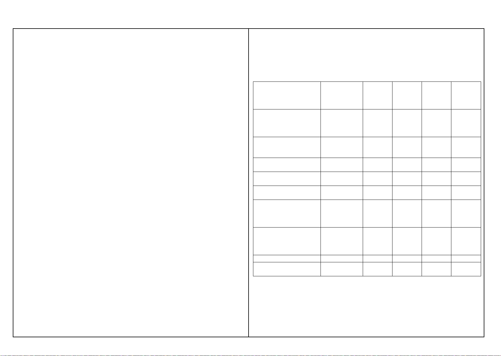
Dimensions et capacité
Appareil Dimensions Poids Nombre
De brûleurs
GAR 7350x510x180 12 kg 1 feu 7 Kw
GAR 12 670x510x180 22 kg 2 (1 feu 7 Kw+1 feu 5 Kw)
GAR 14 670x510x180 22 kg 2 (2 feux 7Kw)
GAR 19 985x510x180 32 kg 3 (2 feux 7 Kw+1 feu 5 Kw)
GAR 21 985x510x180 32 kg 3 (3 feux 7 Kw)
Caractéristiques techniques
Appareil Débit calorifique Nombre de brûleurs
GAR 7 7 Kw 1
GAR 12 12 Kw 2
GAR 14 14 Kw 2
GAR 19 19 Kw 3
GAR 21 21 Kw 3
Fonctionnement
Allumage Ouvrir l’alimentation gaz
Approcher une flamme au niveau de la veilleuse
Pousser et tourner le bouton vers la gauche en position veilleuse
Maintenez le bouton pendant 15 secondes afin que la veilleuse reste allumée
Pour augmenter ou diminuer la position de chauffe, il vous suffit de tourner le bouton dans le
sens désiré.
Un thermocouple coupe l’alimentation en gaz en cas d’extinction du brûleur.
Entretien
Votre appareil doit être régulièrement nettoyé à l’aide d’une éponge humide.
Ne nettoyer pas votre appareil sous un jet d’eau : les infiltrations risqueraient de
l’endommager.
Pour un meilleur service, nous vous conseillons un entretien périodique à faire effectuer par un
installateur qualifié.
Votre appareil peut fonctionner avec les gaz de pétrole liquéfiés ou au gaz naturel. Pour
effectuer l’adaptation d’un gaz à l’autre il est nécessaire d’avoir recours à un installateur
qualifié.
Pour les appareils utilisés en Belgique et en Allemagne l’adaptation d’un gaz à un autre se fait
sous l’entière responsabilité du fabricant ou de son mandataire local.
Installation
Note : Les parois latérales de votre appareil ne doivent pas être situées près d’un mur ou d’une
cloison constituée d’un matériau combustible, ou si ce n’est pas le cas, recouvert d’un matériau
bon isolant thermique.
Une distance de 10cm par rapport à la cloison est jugée suffisante.

Raccordement gaz
Les appareils fonctionnent aux gaz suivants : Butane G30, Propane G31, gaz naturel
G20/G25, et pour toutes les pressions rencontrées sur le réseau de gaz. Le raccordement se
fait par un filetage gaz 3/8.
Les appareils sont livrés d’origine avec un injecteur Butane/Propane correspondant à la
catégorie II2E+3+.
Le débit calorifique de l’appareil est de : GAR 7 7 Kw
GAR 12 12 Kw
GAR 14 14 Kw
GAR 19 19 Kw
GAR 21 21 Kw
Raccorder l’appareil à la canalisation d’amenée de gaz en interposant une vanne de barrage
permettant d’isoler l’appareil du reste de l’installation. Vérifiez que les réglages
correspondent à la nature et à la pression du gaz distribué dans l’installation.
Vérifiez la pression d’alimentation, lorsque tous les brûleurs sont allumés, à l’aide d’un
manomètre. Celle-ci doit être égale aux indications de la plaque signalétique.
Le débit d’air neuf requis pour l’alimentation en air de combustion est de :
GAR 7 14 m3/h
GAR 12 24 m3/h
GAR 14 28 m3/h
GAR 19 38 m3/h
GAR 21 42 m3/h
Conditions générales d’installation
L’installation et l’entretien de l’appareil doivent être effectués conformément aux
textes réglementaires et règles de l’art en vigueur, notamment :
Règlement de sécurité contre l’incendie et la panique dans les établissements
recevant du public :
Prescriptions générales
Pour tous les appareils :
Article GZ Installation aux gaz combustibles et hydrocarbures
liquéfiés.Ensuite, suivant l’usage :
Article CH Chauffage, ventilation, réfrigération, conditionnement
d’air et production de vapeur d’eau chaude sanitaire.
Article GC Installations d’appareils destinés à la restauration
Prescriptions particulières à chaque type d’établissements recevant du public.
Changement de gaz
Important : Ne jamais repercer les injecteurs.
Tableau des catégories de gaz, selon le pays de destination de l’appareil.
Pays de destination Catégorie Gaz Pressions Diamètre de
l’injecteur
brûleur 5
Kw
Diamètre de
l’injecteur
brûleur 7
Kw
France/Luxembourg II2E+3+
II2E+3B/P
G20/G25
G30/G31
G20/G25
G30/G31
20/25
28-30/37
20/25
50
160
105
160
105
190
13
0
190
130
Allemagne II2ELL3B/P G20
G25
G30/G31
20
20
50
160
160
105
190
190
130
Autriche II2H3B/P G20
G30/G31 20
50 160
105 190
130
Belgique I3+
I2E+ G30/G31
G20/G25 28-30/37
20/25 105
160 13
0
190
Suède/Danemark/Finla
nde II2H3B/P G20
G30/G31 20
30 160
105 19
0
130
Espagne II2H3+
II2H3P
G20
G30/G31
G20
G31
20
28-30/37
20
50
160
105
160
105
190
130
190
130
Pays-Bas II2L3B/P
II2L3P
G25
G30/G31
G25
G31
25
30
25
50
160
105
160
105
190
13
0
19
0
130
Norvège I3B/P G30/G31 30 105 130
Islande/Grèce/Royaum
e-Uni/Italie/Portugal II2H3+ G20
G30/G31 20
28-30/37 160
105 19
0
130
Dans le cas d’une utilisation au gaz naturel, changer les injecteurs des brûleurs, changer
l’injecteur de la veilleuse (diam 40), dévisser complètement l’écrou puis l’injecteur situé dans
le trou.

Instructions for use and installation
Gas stove GAR 7-GAR 12-GAR 14-GAR 19-GAR 21
USE
Description of the appliance
Gas stoves are supplied with 1, 2 or 3 burners.
The control of fires of cooking is independent, with a system of night light to the lighting and a
thermocouple of safety. The gas stoves are equipped with several entirely removable parts:
cast iron grid, crown burner, vat stainless and machine washable
These appliances are for professional use and must therefore be used by qualified personnel.
They must be installed in accordance with current regulations by a qualified installer.
Unpack the appliance carefully from its original packaging. Place it on a flat surface.
The identification plate is located on the back of the appliance.
Dimensions and capacity
Appliance Dimensions Weight Number of burners
GAR 7350x510x180 12 kg 1 feu 7 kw
GAR 12 670x510x180 22 kg 2 (1 feu 7 Kw+1 feu 5 Kw)
GAR 14 670x510x180 22 kg 2 (2 feux 7 Kw)
GAR 19 985x510x180 32 kg 3 (2 feux 7 Kw+1 feu 5 Kw)
GAR 21 985x510x180 32 kg 3 (3 feux 7 Kw)
Technical data
Appliance Heat output Number of burners
GAR 7 7 Kw 1
GAR 12 12 Kw 2
GAR 14 14 Kw 2
GAR 19 19 Kw 3
GAR 21 21 Kw 3
Operation
Lighting Open the food gas
Approach a flame on the level night light
Push it and turn the button towards the left in position night light
Maintain the button for 15 seconds so that the night light remains lit
To increase or decrease the position of heating, you just have to turn the button in the desired
direction.
A thermocouple cuts the gas supply in the event of extinction of the burner.
Care and maintenance
Your appliance should be cleaned regularly with a damp sponge.
Do not clean your appliance under running water: water entering the system might damage it.
For improved service, we advise that periodic maintenance checks are carried out by a
qualified installer.
Your appliance can operate on liquid petroleum gas or natural gas. To change from one gas to
another requires the intervention of a qualified installer.
For appliances used in Belgium and Germany, changing from one gas to another is the sole
responsibility of the manufacturer or his local agent.
Installation
NB: The side panels of your appliance must not be placed next to a wall or partition made
from a combustible material; otherwise, they should be covered in an effective heat insulating
material.
A distance of 10 cm from the partition is deemed sufficient.

Gas connection
The appliances operates on the following gases : Butane G30, Propane G31, natural gas
G20/25 and at all pressures encountered on mains gas. Connection is with a ½ threat
The appliances are supplied from the factory with a Butane/Propane injector corresponding to
category II2E+3+.
The heat output of the appliance is : GAR 7 7 Kw
GAR 12 12 Kw
GAR 14 14 Kw
GAR 19 19 Kw
GAR 21 21 Kw
Connect the appliance to the gas supply pipe, interposing a stop valve which enables the
appliance to be isolated from the rest of the installation. Check that the setting corresponds to
the type and pressure of the gas distributed in the installation.
Check the supply pressure with all the burners alight using a gas manometer. This should be
the same as indicated on the identification plate.
The fresh air flow required to provide air for combustion is :
GAR 7 14 m3/h
GAR 12 24 m3/h
GAR 14 28 m3/h
GAR 19 38 m3/h
GAR 21 42 m3/h
General conditions for installation
The installation and maintenance of the appliance must be carried out in accordance
with the current regulations and rulebook, in particular:
Regulations for the prevention of fire and panic in establishments to which the public
is admitted.
General provisions:
For all appliances:
Article GZ Installations using combustible gases and liquid
hydrocarbons
Next, depending on the use:
Article CH Heating, ventilation, refrigeration, air conditioning and the
production of steam from hot water in sanitary installations.
Article GC Installation of appliances to be used for catering
Specific provisions for each type of establishment to which the public is admitted
(hospitals, shops, etc...)
.
Changing the gas
Important: Do not bore again the injectors.
Table of gas categories, according to country of destination of the appliance
Country of destination Category Gas Pressures Diameter
of injector
burner 5
Kw
Diameter
of injector
burner 7
Kw
France/Luxembourg II2E+3+
II2E+3B/P
G20/G25
G30/G31
G20/G25
G30/G31
20/25
28-30/37
20/25
50
160
105
160
105
190
130
190
130
Germany II2ELL3B/P G20
G25
G30/G31
20
20
50
160
160
105
190
190
130
Austria II2H3B/P G20
G30/G31 20
50 160
105 190
130
Belgium I3+
I2E+ G30/G31
G20/G25 28-30/37
20/25 105
160 130
190
Sweden/Denmark/Finland II2H3B/P G20
G30/G31 20
30 160
105 190
130
Spain II2H3+
II2H3P
G20
G30/G31
G20
G31
20
28-30/37
20
50
160
105
160
105
190
130
190
130
Netherlands II2L3B/P
II2L3P
G25
G30/G31
G25
G31
25
30
25
50
160
105
160
105
190
130
190
130
Norway I3B/P G30/G31 30 105 130
Iceland/Greece/United
Kingdom/ Italy/Portugal II2H3+ G20
G30/G31 20
28-30/37 1
60
105 190
130
If natural gas is to be used, change the injectors of the burners, change the pilot light injector
(diam 40), as per the diagram below (unscrew the nut completely then the injector located in
the hole).
Other manuals for GAR 7
1
This manual suits for next models
4
Table of contents
Languages:
Other Roller Grill Stove manuals
Popular Stove manuals by other brands

Morso
Morso 5660 Standard Insert Instructions for installation and use

Inca
Inca Tasman 40 Operating and installation instructions

Broseley
Broseley Q7 Installation & operating instructions

Reading Stove Company
Reading Stove Company MAHANTONGO CS-45 owner's manual

Nordpeis
Nordpeis Quadro user manual

Nordica
Nordica FALO Instructions for installation, use and maintenance