2 3
FRONT PANEL DESCRIPTION
NOTE:Channel One descriptions are identical to ChannelTwo
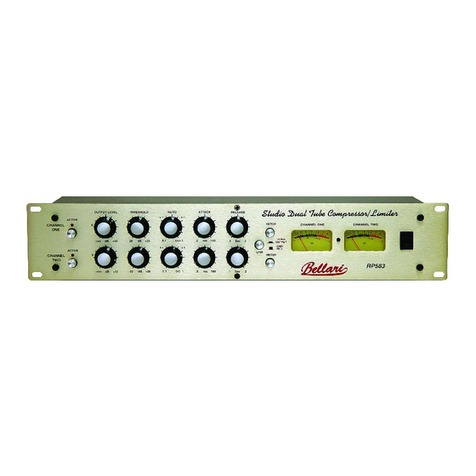
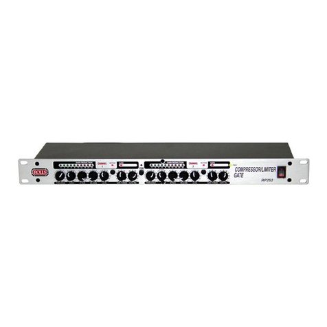
ACTIVE SWITCH:Engages and disengages the compression.
OUTPUT LEVEL:Varies the overall signal level from the RP282.
THRESHOLD:Sets the level at which the incoming signal must overcome in order
for the RP282 to begin compressing.
RATIO: Adjusts the signal to compression ratio.This sets the amount of increase
in input signal required to raise the output signal 1 dB.
ATTACK:Varies the amount of time taken for the RP282 to begin compressing
after theThreshold level has been reached.
RELEASE:Varies the amount of time taken for the RP282 to return to normal gain
once the signal has dropped below theThreshold level.
METER SWITCH:Switched the signal metering from indicating the output jack
level, to indicating the amount of gain reduction.
VU METER:Indicates either the output signal level, or the amount of gain reduc-
tion, depending on the position of the Meter Switch.
NOTE:THE INPUT SIGNAL LEVEL MAY ALSO BE INDICATED BY PRESSING
OUTTHE ACTIVE SWITCH AND BYPASSINGTHE COMPRESSOR CIRCUITS.
POWER SWITCH:Turns the RP282 main power on and off.
CAUTION
WARNING:
DO NOT EXPOSE THIS EQUIPMENT TO RAIN
OR MOISTURE.
CAUTION:
TO REDUCE THE RISK OF ELECTRIC SHOCK DO NOT
NOT REMOVE BACK. NO USER SERVICABLE PARTS INSIDE. REFER
SERVICING TO QUALIFIED SERVICE PERSONNEL.
RISQUE DE CHOC - NE PAS ENLEVER
RISK OF ELECTRIC SHOCK
DO NOT OPEN
120 VAC
50/60 Hz 15 VA
MADE IN U.S.A.
MODEL RP583
SERIAL NUMBER
583-
OUTPUT
CHANNEL TWO
SIDE CHAIN
INPUT OUTPUT
CHANNEL ONE
SIDE CHAIN
INPUT
BAL UNBAL INPUT OUTPUT UNBAL BAL BAL UNBAL INPUT OUTPUT UNBAL BAL
20 10 5
3
036
@ *
+4 REF
OUTPUT
GAIN
REDUCTION
Channel
One
Channel
Two
ACTIVE
OUTPUT LEVEL THRESHOLD RATIO ATTACK RELEASE
METER
ACTIVE
- OO 0 -25 dB +10 .5 ms 100 100 ms 500
-25 dB +10 .5 ms 100 100 ms 500
METER CHANNEL ONE CHANNEL TWO
Dual Tube Compressor/Limiter
RP282a
2:1 OO:1
2:1 OO:1
- OO 0
4:1 5:1
4:1 5:1
STEREO
LINK
20 10 5
3
036
@ *
REAR PANEL DESCRIPTION
NOTE:Channel One descriptions are identical to ChannelTwo.
OUTPUTS:XLR balanced and 1/4”unbalanced connectors for connecting the
RP282 to a mixer or other line level input.
SIDE CHAIN INPUT:1/4”unbalanced jack for receiving incoming signals to
directly access the detector circuit of the compressor.
SIDE CHAIN OUTPUT:1/4’unbalanced jack for sending out the signal from the
RP282.This jack may also be used as a pre-Output Level output.IMPORTANT:
The Side Chain Inputs and Outputs are not effects loops, they break the
signal path of the RP282 control circuitry.
INPUTS:XLR balanced and 1/4”unbalanced connectors for connecting line level
signals to the RP282.
SPECIFICATIONS
Frequency Response: 10 Hz - 40 kHz
InputImpedance: 10K 9balanced
1M 9unbalanced
THD + Nosie: 0.1% typical
S/N Ratio: 103 dB
Max Gain: 40 dB (Threshold @ -40 dB)
Indicators: (2) Active LEDs, (2) analogVU meters
Input/Output jacks: XLR balanced and 1/4”unbalanced
Dimensions: 3.5”x 6”x 19”(89 x 162 x 482 mm)
Power: 120 VAC, (230 VAC) 15 VA
Approval: CSA NRTL (Pending)
