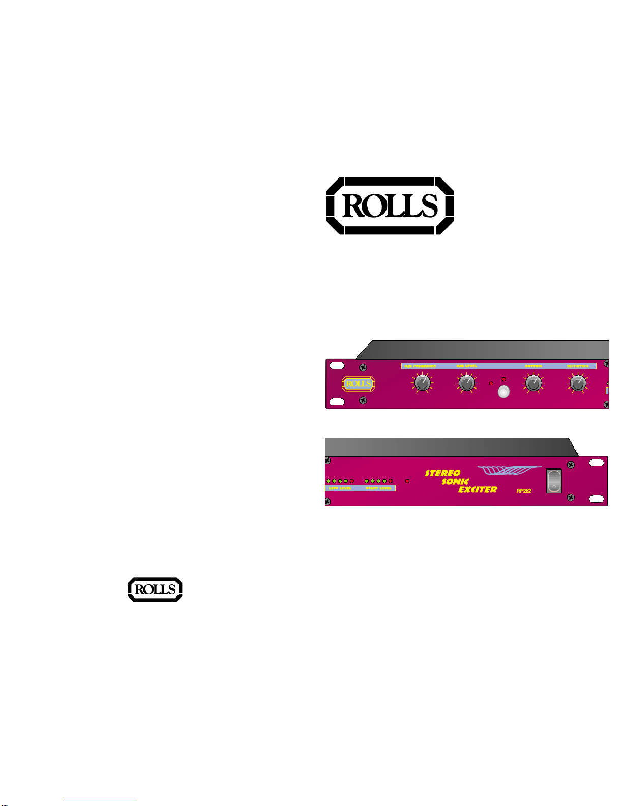
FRONT PANEL DESCRIPTION
SUB FREQUENCY:Sets the highest frequency allow ed out of the Sub W oofer
Outputs.This frequency is adjustable between 35Hz and 200Hz.
SUB LEVEL: Adjusts the output level of the Sub W oofer Outputs.The levelis
adjustable between -infinity (off) and a gain of +20 dB .
SUB CLIP LED: When lit, this LED indicates the signal level is 3 dB belo w clipping
and there may be distor tion in the Sub W oofer circuits .
ACTIVE SWITCH: Engages and disengages the RP262 process.When out, the
eff ect is bypassed.
B O T TO M : Controls the lo w frequency cut/boost (flat or no cut/boost is at about 11
O’clock). There is a 0 to 1/2 tur n spectr um spread from mid-range to bass with
this control as w ell as amplitude control.
DEFINITION: Controls the amount of sonic clar ity and sound spread. Setting it on
0 is flat response and minimal spread, on 10 is maximum spread and definition.
This is also a good setting for constant dispersion hor ns.
LEFT/RIGHT LEVEL LEDS: Indicates the output level of each channel.
PWR LED: Indicates that the RP262 is connected to an AC outlet, and the pow er
istur ned on.
P OWER SWITCH: Controls the pr imar y pow er to the RP262.
ACTIVE
-OO+20
SUB FREQUENCY
35 Hz 200
SUB LEVEL BOTTOM DEFINITION
0 10 0 10
50
100
175
RIGHT LEVEL
-13 -7 0 +10 +17
LEFT LEVEL
-13 -7 0 +10 +17
POWER
SUB
CLIP
S T E R E O
S O N I C
E X C I T E R
R P 2 6 2
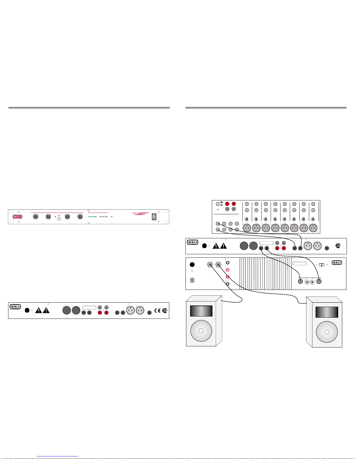
REAR PANEL DESCRIPTION
P OWER CORD: Provides pow er to the RP262 from a properlygrounded AC
outlet.
RIGHT/LEFT XLR OUTPUTS: Balanced outputs for connection to a pow er
amplifier.
RIGHT/LEFT 1/4” OUTPUTS: Unbalanced outputs.
LEFT/RIGHT 1/4” INPUTS: Unbalanced inputs for connection (nor mally) to the
last de vice in the signal chain bef ore the po w er amplifier .
LEFT/RIGHT XLR INPUTS: Balanced inputs. See above.
SUB OUTPUT:1/4” unbalanced output for connection to the Sub W oofer pow er
amplifier.
RCA INPUTS: Unbalanced inputs.
RCA OUTPUTS: Unbalanced outputs.
WARNING:
DO NOT EXPOSE THIS EQUIPMENT TO RAIN OR MOISTURE
.
120 VAC
50/60 Hz 15 VA
MODEL RP262
MADE IN U.S.A.
SERIAL NUMBER
262-
LEFT
OUTPUT
RIGHT
OUTPUT LEFT
OUTPUT
RIGHT
OUTPUT SUB
OUTPUT
LEFT
INPUT
RIGHT
INPUT
LEFT
INPUT
RIGHT
INPUT
RISQUE DE CHOC - NE PAS ENLEVER
OUTPUT INPUT
RIGHT
LEFT
NRTL /C
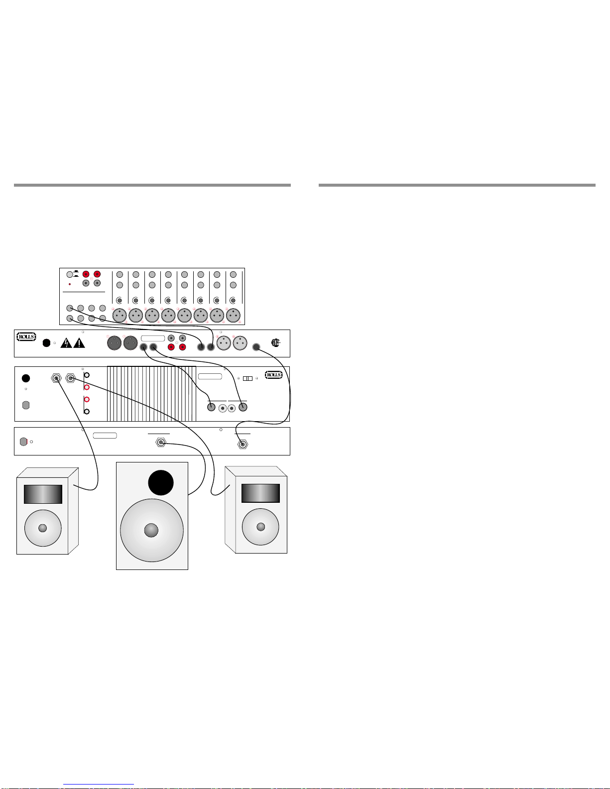
OPERATION
STEREO CONNECTION
The diagram shown below is a stereo connection example for the RP262. We
recommend you put the RP262 last in the signal chain. Ifyou have an EQ or other
processor after your mixer’s main outputs, inser t the RP262 between it and your
po w er amplifier .
Ifyou are connecting the RP262 into a home stereo system, inser t the Sonic
Exciter between your signal sources such as tuners, cassette pla yers , CD pla yers
etc. and the pow er amplifier.
C AUTION: TO AVOID POSSIBLE SPEAKER OR AMPLIFIER DA M AGE, ALW AY S
TURN ON THE RP262 AND OTHER PERIPHERAL EQUIPMENT BEFORE
TURNING ON THE POWER AMPLIFIERS.ALSO TURN OFF THE POW E R
AMPLIFIERS FIRST, BEFORE TURNING OFF THE RP262 AND OTHER EQUIP-
MENT.
WARNING:
DO NOT EXPOSE THIS EQUIPMENT TO RAIN OR MOISTURE
.
120 VAC
50/60 Hz 15 VA
MODEL RP262
MADE IN U.S.A.
SERIAL NUMBER
262-
LEFT
OUTPUT
RIGHT
OUTPUT LEFT
OUTPUT
RIGHT
OUTPUT SUB
OUTPUT
LEFT
INPUT
RIGHT
INPUT
LEFT
INPUT
RIGHT
INPUT
RISQUE DE CHOC - NE PAS ENLEVER
OUTPUT INPUT
RIGHT
LEFT
NRTL /C
TAPE
OUT TAPE
IN
R
L
TRIM
LINE
INSERT
MIC 1
INSERTINSERT
INSERT
LINELINELINE
TRIM
TRIMTRIMTRIMTRIM
TRIMTRIM
PHANTOM POWER LEFT
RIGHT
LEFT
RIGHT
LEFT
RIGHT
LEFT
RIGHT
LEFT OUT
RIGHT OUT AUX 1
RET. RIGHT AUX 2
OUT
AUX 1
OUT
MIC 2
MIC 3MIC 4MIC 5/6MIC 7/8MIC 9/10MIC 11/12
+48V
OFF
+10
+60
+10
+60
+10
+60
+10
+60
+10
+60
+10
+60
+10
+60
+10
+60
AUX 2
RET. LEFT
AUX 2
RET. RIGHT
POWER
AUX 1
RET. LEFT
MADE IN U.S.A.
RISQUE DE CHOC - NE PAS ENLEVER
SERIAL NUMBER
WARNING:
To reduce the risk of electric
shock or fire do not expose
this device to rain or moisture.
CHANNEL 2 INPUT CHANNEL 1 INPUT
BRIDGE NORMAL
OUTPUT 2 OUTPUT 1
4A 120V - 2A 230 V
OUTPUT 1
OUTPUT 2
-
-
+
+
MAINS POWER
WARNING
For continued prootection against
risk of fire, replace only with
same type and rating of fuse.
CAUTION
TO REDUCE THE RISK OF ELECTRIC
SHOCK DO NOT NOT REMOVE LID. NO
USER SERVICABLE PARTS INSIDE.
REFER SERVICING TO QUALIFIED
SERVICE PERSONNEL
C O R P O R A T I O N
MIXER
POWER
AMPLIFIER