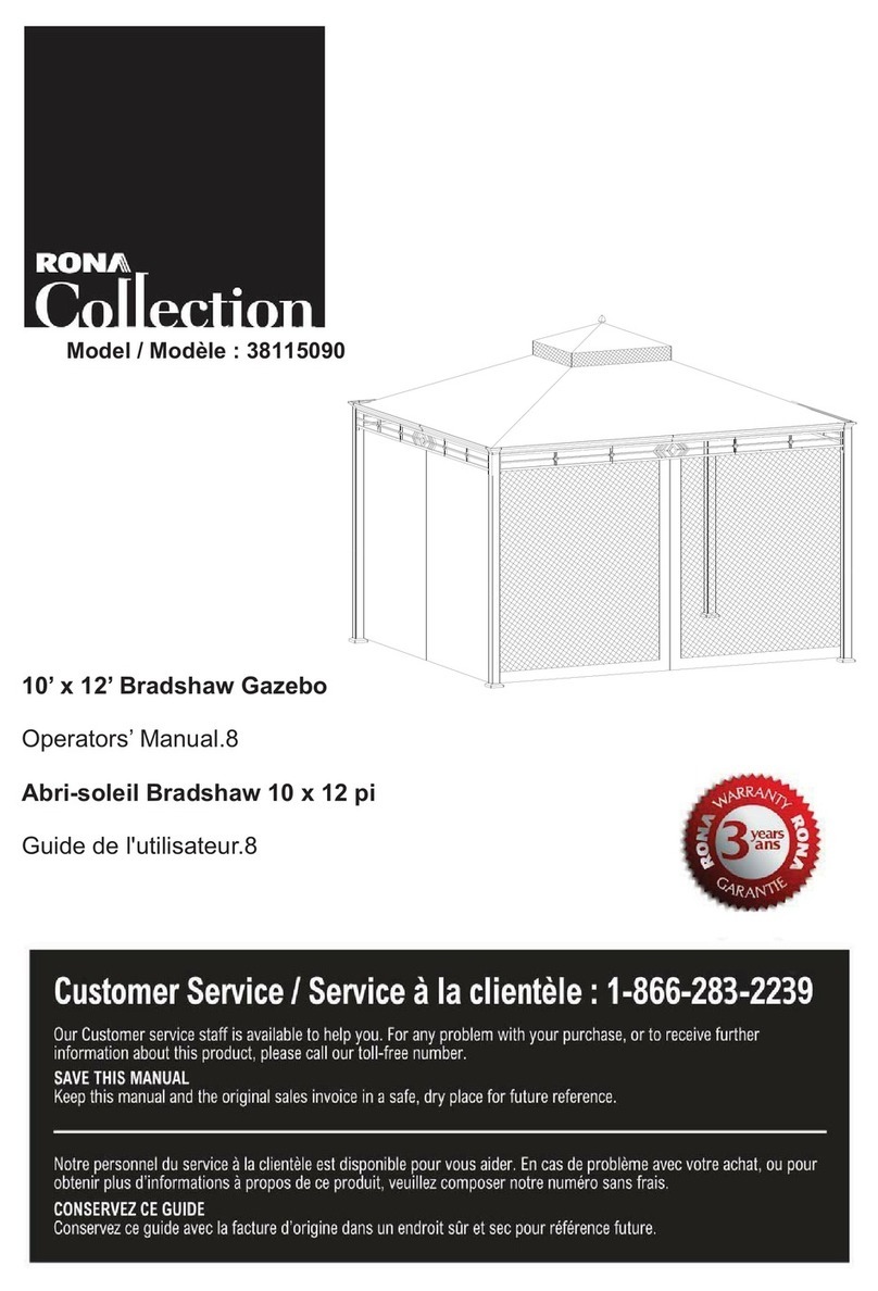
Rona 38115088 User manual

Page 1
Model / Modèle : 38115088
10 x 12’ Gazebo
Operators’ Manual (p.2)
Abri-soleil 10 x 12 pi
Guide de l'utilisateur (p.12)

Page 2
GAZEBO ASSEMBLY INSTRUCTIONS
Our clear, easy-to-follow, step-by-step instructions will guide you through the
project from start to finish.
All that is required is a screwdriver, a hammer and two ladders of at least 8 feet
(2.5 m) high. (not included).
For you safety, DO NOT assemble this item alone. Six people or more are
required for a smooth and safe installation.
Item identification: For ease of identification, all parts are labeled to correspond to
the Step number in which the part is used.
Have six or more people helping you when assembling or
moving the product.

Page 3
Description Part Quantity Image
Short post A 2
Long post B 2
Small slanted beam C4
Small connector D1
Hook E 1
Small cover F1 2
Long roof piece 2 F2 2
Long roof piece 3 F3 2
Cover board G 4
Top cover board H 1
Big panel 1 I1 2
Big panel 2 I2 2
Small panel 1 I3 2
Small panel 2 I4 2
Fence I5 8
Connector J1 4
Top connector J2 4
Lower connector J3 4
Short beam 1 K1 2
Short beam 2 K2 2
Long beam 1 K3 2
Long beam 2 K4 2
Parts List

Page 4
Description Part Quantity Image
Left netting tube 1 M1 2
Right netting tube 2 M2 2
Left netting tube 3 M3 2
Right netting tube 4 M4 2
Top slanted beam N1 4
Top post N2 4
Roof piece 1 O1 4
Roof piece 2 O2 2
Roof piece 3 O3 4
Roof piece 4 O4 2
Roof piece 5 O5 2
Roof piece 6 O6 2
Roof piece 7 O7 2
Roof piece 8 O8 2
Roof piece 9 P 2
Roof piece 10 Q 4
Beam 1 R1 2
Beam 2 R2 2
Beam 3 R3 2
Beam 4 R4 2
Beam 5 R5 2
Beam 6 R6 2
Long beam 1 S1 2
Long beam 2 S2 2

Page 5
Description Part Quantity Image
Long beam 3 S3 2
Long beam 4 S4 2
Long beam 5 S5 2
Long beam 6 S6 2
Fixed beam 1 T1 2
Fixed beam 2 T2 2
Big fixed beam 1 U1 4
Big fixed beam 2 U2 2
Big fixed beam 3 U3 2
Top cover flap U4 2
Small top beam 1 V1 2
Small top beam 2 V2 2
Panel wall W 8
Mosquito net X 1
Part Description Quantity Image
AA M6 x 15 Bolt 64PCS
BB M6 Flat washer 124PCS
CC M6 x 65 Bolt 16PCS
DD M6 Nut 16PCS
EE M6 x 25 Bolt 12PCS
FF M6 x 35 Bolt 16PCS
Z M6 Wrench 2 PCS
Hardware Pack 1

Page 6
Fig.1: Secure the fence (I5) to
the panel with bolts (AA) and
flat washers (BB).
Fig.5: Secure the connector
(J1) to the beams with bolts
(AA) and flat washers (BB).
Fig.2: Connect big panel 1 (I1) and small panel 1 (I3)
with bolt (EE), flat washer (BB). Repeat this step for big
panel 2 (I2) and small panel 2 (I4).
Fig.4: Attach long beam 1 (short
beam 2) K3 (K2) / long beam 2 (short
beam 1) K4 (K1) to I1 (I4) / I3 (I2) with
bolts (FF), flat washers (BB), and
bolts (AA), flat washers BB.
Fig.3: Insert short beam 1 /
long beam 2 (K1) / (K4) into
connection hole in short
beam 2 / long beam 1 (K2) /
(K3) and tighten with bolts
(CC), flat washers (BB) and
nuts (DD).

Page 7
Part Description Quantity Image
AA M6 x 15 Bolt 28PCS
BB M6 Flat washer 166PCS
LL 20 Flat washer 2PCS
HH M6 x 55 Screw 22PCS
DD M6 Nut 20PCS
I I M6 x 45 Bolt 8PCS
GG M6 x 15 Screw 88PCS
Hardware Pack 2
Fig.6: Secure the short post (A) with long post (B) with bolts
(AA) and flat washers (BB).
Fig.7: Secure the small
slanted beam ˄C˅with
bolts (AA) and flat washers
(BB).

Page 8
Fig.10: Secure the top end of
the top slanted beam (N1) to
the top frame with bolts (AA)
and flat washers (BB).
Fig.8-1: Assemble
the hook (E) to the
small connector (D).
Fig.14: Assemble the cover board (G) to the small slanted beam (C)
with bolts (II) and flat washers (BB). Assemble the top cover board
(H) to the small connector (D) with screws (HH) and flat washers
(BB & LL).
Fig.8: Assemble the small
slanted beams (C) to the small
connector (D) with nuts (DD),
flat washers (BB) and screws
(HH).
Fig.9: Secure the top
slanted beam (N1) to the
connector (J1) with screws
(HH), flat washers (BB) and
nuts (DD).
Fig.12: Secure the middle
beam (N2) to the top frame
with bolts (AA) and flat
washers
(
BB
)
.
Fig.11: Secure the lower end of the
top post (N2) to the beam
connector with screws (HH), flat
washers (BB) and nuts (DD).
Fig.13: Assemble the roof piece 2 (F2) to the roof piece 3(F3), then secure the small roof piece (F1) and long roof piece (F2 and
F3) to the small slanted beam with screws (GG) and flat washers (BB).
Fig.14-1: Secure the fixed
beams (T1 and T2) to the
roof pieces (F1, F2 and
F3) with screws (GG) flat
washers (BB).
Fig.8-2: Secure the small
top beams (V1 and V2) to
the small slanted beam
(C) with screws (GG) and
flat washers (BB).

Page 9
Part Description Quantity Image
AA M6 x 15 Bolt 2PCS
GG M6 x 15 Screw 48PCS
BB M6 Flat washer 58PCS
II M6 x 45 Bolt 8PCS
Hardware Pack 3
Fig.19-1: Secure one end
of the netting tubes (M1ˈ
M2ˈM3ˈM4) to the top
post (N2) with screws
(GG) and flat washers
(BB).
Fig.15: Secure the long
beams (S1, S2, S3 and
S4) to the top post (N2)
with screws (GG) and flat
washers (BB). Repeat this
step to secure the beams
(R1, R2, R3 and R4).
Fig.16: Secure the other end of
the long beams (S1, S2, S3 and
S4) to the top slanted beam
(N1) with screws (GG) and flat
washers (BB). Repeat this step
to secure the beams (R1, R2,
R3 and R4).
Fig.17: Secure the long
beams (S5 and S6) to the
top post (N2) with screws
(GG) and flat washers (BB).
Repeat this step to secure
the beams (R5 and R6).
Fig.18: Secure the long
beams (S5 and S6) to the
top slanted beam (N1) with
screws (GG) and flat
washers (BB). Repeat this
step to secure the beams
(R5 and R6).
Fig.19-2: Secure the other end
of the netting tubes (M1ˈM2ˈ
M3, M4) to the top slanted
beam (N1) with screws (GG)
and flat washers (BB).

Page 10
Fig.20: Assemble the roof
piece 3 (O3) to the roof
piece 5 (O5). Repeat for
this step to assemble
cover 9(P) and cover 3
Fig.21: Secure the roof
pieces (O5 and P) to the
top slanted beams (N1)
with screws (GG) and flat
washers (BB). Repeat this
step to secure the roof
piece 6 (O6).
Fig.22: Assemble the roof
piece 1 (O1) to the roof
piece 3 (O3); repeat for
roof pieces 4 (O4) and
roof piece 2 (O2). Use
screws (GG) and flat
washers (BB) to secure
to the top slanted beams
(N1).
Fig.23: Assemble the roof
piece 7 (O7) on the roof
piece 8 (O8); repeat for
roof piece 1 (O1) and roof
pieces 3 (O3). Use screws
(GG) and flat washers
(BB) to secure to the top
slanted beam (N1).
Fig.24: Secure the roof
piece 10 (Q) to the beam
with bolts (II) and flat
washers (BB).
Part Description Quantity Image
JJ ĭ x 260mm Stake 16PCS
KK Ring 67PCS
Hardware Pack 4
Fig.25-1: Secure top cover
flap (U4) with bolt (AA) and
flat washers (BB).
Fig.25: Put U1 onto the top of S5 (S6) and
tighten them with GG, BB. And then,
tighten U2 and the left side of R5 with GG,
BB. Lastly, tighten U3 and the right side of
R6 with GG and BB.

Page 11
Fig.28: Secure the whole
gazebo to the ground with
stakes (JJ).
Fig.26: Assemble the panel
wall˄w with velcro straps.
Fig.27: Hang the mosquito
net (X) onto the netting
tubes (M1, M2, M3 and
M4) with rings (KK).

Page 12
IMPORTANT
1. Keep all children and pets away from assembly area. Children and pets should be
supervised while gazebo is being assembled.
:
2. The assembled gazebo should be located at least 6 feet (2 m) from any obstruction
such as a fence, garage, house, overhanging branches, laundry lines or electrical wires.
3. This unit is heavy. Do not assemble this item alone. Six people are recommended for
safe assembly.
4. Some parts may contain sharp edges. Wear protective gloves if necessary during
assembly.
5. When assembling and using this product, basic safety precautions should always be
followed to reduce the risk of personal injury and damage to equipment. Please read all
instructions before assembly and use.
6. For outdoor use only. Install on level ground. 16 stakes are provided to secure the
gazebo in the ground. If you wish to secure the gazebo to a wood deck or concrete
surface, use 16 anchors suited for these surfaces (anchors not included).
7. Check all bolts for tightness before and during usage.
8. Please check your state and local regulations prior to purchasing. Some jurisdictions
may require permits for installation and use. Some special procedures may be valid in
your area.
9. While this gazebo is manufactured to withstand strong force winds through only the
supplied ground stakes, securing the gazebo to a deck, concrete patio or a stronger base,
in areas subject to frequent severe weather should be considered.
NOTE: The gazebo’s roof and structure are not guaranteed against extreme weather
conditions (storms, high winds, etc.). If the gazebo is not dismantled for the winter, snow
must be cleaned off regularly. Any damage caused by snow accumulation is not covered
by the warranty.
Our steel components for garden accessories and furniture are treated with rust inhibiting
paint to protect it from rusting. However, due to the nature of steel, surface oxidation
(rusting) will occur once these protective coatings are scratched. This is not considered a
defect and thus cannot be covered by the warranty.
Care & Maintenance:
To minimize this condition, we recommend care when assembling & handling the product
to prevent scratching the paint. Should any scratching or damage occur, we recommend
immediate touch-up with rust inhibiting paint.
Surface rust can also be easily removed with a very light application of common cooking
oil. If surface oxidation (rusting) occurs and if no measure is taken to prevent this, the
oxidation may drip on to the deck or patio and caused damaging stains, which may be
difficult to remove. This can be prevented if the above-mentioned measures are taken to
keep the product from oxidizing.

Page 13
DIRECTIVES D’ASSEMBLAGE DE L’ABRI-SOLEIL
Nos instructions étape par étape, claires et faciles à suivre vous aideront à
assembler votre abri facilement, du début à la fin.
Vous aurez besoin d’un tournevis, un marteau et deux échelles d'au moins 8 pi
(2,5 m) de hauteur (non fournis).
Pour votre sécurité, N’ASSEMBLEZ PAS cet article seul. Six personnes ou
plus seront requises pour une installation facile et en toute sécurité.
Identification des pièces : pour faciliter leur identification, toutes les pièces sont
étiquetées et l'étiquette correspond au numéro de l’étape dans laquelle la pièce
sera utilisée.
Assurez-vous d’avoir l’aide de six personnes ou plus lors de
l’assemblage ou du déplacement du produit.

Page 14
Description Pièce Quantité Image
Pilier court A 2
Pilier long B 2
Petite poutre oblique C4
Petit raccord D1
Crochet E 1
Petit pan F1 2
Petit pan 2 F2 2
Petit pan 3 F3 2
Planche de recouvrement G 4
Planche de recouvrement
supérieure H1
Grand panneau 1 I1 2
Grand panneau 2 I2 2
Petit panneau 1 I3 2
Petit panneau 2 I4 2
Grille I5 8
Raccord J1 4
Raccord supérieur J2 4
Raccord inférieur J3 4
Poutre courte 1 K1 2
Poutre courte 2 K2 2
Poutre longue 1 K3 2
Poutre longue 2 K4 2
Liste des pièces

Page 15
Description Pièce Quantité Image
Tube à moustiquaire gauche 1 M1 2
Tube à moustiquaire droit 2 M2 2
Tube à moustiquaire gauche 3 M3 2
Tube à moustiquaire droit 4 M4 2
Poutre oblique supérieure N1 4
Pilier supérieur N2 4
Pan 1 O1 4
Pan 2 O2 2
Pan 3 O3 4
Pan 4 O4 2
Pan 5 O5 2
Pan 6 O6 2
Pan 7 O7 2
Pan 8 O8 2
Pan 9 P 2
Pan 10 Q 4
Poutre 1 R1 2
Poutre 2 R2 2
Poutre 3 R3 2
Poutre 4 R4 2
Poutre 5 R5 2
Poutre 6 R6 2
Poutre longue 1 S1 2
Poutre longue 2 S2 2

Page 16
Description Pièce Quantité Image
Poutre longue 3 S3 2
Poutre longue 4 S4 2
Poutre longue 5 S5 2
Poutre longue 6 S6 2
Poutre fixe 1 T1 2
Poutre fixe 2 T2 2
Grande poutre fixe 1 U1 4
Grande poutre fixe 2 U2 2
Grande poutre fixe 3 U3 2
Clapet supérieur U4 2
Petite poutre supérieure 1 V1 2
Petite poutre supérieure 2 V2 2
Panneau mural W 8
Moustiquaire X 1
Part Description Quantité Image
AA BoulonM6x15 64PCES
BB Rondelle plate M6 124 PCES
CC BoulonM6x65 16PCES
DD Ecrou M6 16 PCES
EE BoulonM6x25 12PCES
FF BoulonM6x35 16PCES
ZCléM6 2PCES
Quincaillerie -
p
a
q
uet 1

Page 17
Fig.1 : Fixez la grille (I5) au
panneau avec des boulons
(AA) et des rondelles plates
(BB).
Fig.5 : Fixez le raccord (J1)
aux poutres avec des boulons
(AA) et des rondelles plates
(BB).
Fig.2 : Fixez le grand panneau 1 (I1) et le petit panneau
1 (I3) avec des boulons (EE) et des rondelles plates
(BB). Répétez cette étape avec le grand panneau 2 (I2)
et le petit panneau 2 (I4).
Fig.4 : Assemblez la poutre longue 1
(poutre courte 2) K3 (K2) / la poutre
longue 2 (poutre courte 1) K4 (K1)
avec I1 (I4) / I3 (I2) àl’aide de
boulons (FF), de rondelles plates
(BB), et de boulons (AA).
Fig.3 : Insérez la poutre courte 1
/ la poutre longue 2 (K1) / (K4)
dans le trou d’assemblage de la
poutre courte 2 / la poutre
longue 1 (K2) / (K3) et les
assembler avec des boulons
(CC), des rondelles plates (BB)
et des écrous (DD).

Page 18
Part Description Quantité Image
AA BoulonM6x15 28PCES
BB Rondelle plate M6 166 PCES
LL Rondelle plate20 2PCES
HH VisM6x55 22PCES
DD Ecrou M6 20 PCES
II Boulon M6 x 45 8 PCES
GG VisM6x15 88PCES
Quincaillerie -paquet 2
Fig.6 : Assemblez le pilier court (A) et le pilier long (B) à l’aide de
boulons (AA) et de rondelles plates (BB).
Fig.7 : Fixez la petite poutre
oblique avec des boulons
(AA) et des rondelles plates
(BB).

Page 19
Fig.10 : Fixez l’extrémité
supérieure de la poutre
oblique au cadre supérieur
avec des boulons (AA) et des
rondelles plates (BB).
Fig.8-1 : Assemblez
le crochet (E) et le
petit raccord (D).
Fig.14 : Assemblez la planche de recouvrement (G) et la petite
poutre oblique (C) avec des boulons (II) et des rondelles plates
(BB). Assemblez la planche de recouvrement supérieure (H) avec le
petit raccord (D) avec des vis (HH) et des rondelles plates (BB/LL).
Fig.8 : Assemblez la petite
poutre oblique (C) avec le
petit raccord (D) avec des
écrous (DD), des rondelles
plates (BB) et des vis (HH).
Fig.9: Fixez la poutre
oblique supérieure (N1) au
raccord (J1) avec des vis
(HH), des rondelles plates
(BB) et des écrous (DD).
Fig.12 : Fixez la poutre
médiane au cadre supérieur
avec des boulons (AA) et des
rondelles plates (BB).
Fig.11 : Fixez la partie inférieure du
pilier supérieur (N2) au raccord de
la poutre avec des vis (HH), des
rondelles plates (BB) et des écrous
(DD).
Fig.13 : Assemblez le long pan 2 (F2) au long pan 3 (F3), puis fixez le petit pan (F1) et les longs pans (F2 et F3) à la petite
poutre oblique avec des vis (GG) et des rondelles plates (BB).
Fig.8-2 : Fixez les petites
poutres supérieures (V1 et
V2) à la petite poutre
oblique (C) avec des vis
(GG) et des rondelles
plates (BB).
Fig.14-1 : Fixez les
poutres fixes (T1 et T2)
aux pans (F1, F2 et F3)
avec des vis (GG) et des
rondelles plates (BB).

Page 20
g
Pièce Description Quantité Image
AA Boulon M6 x 15 2 PCES
GG VisM6x15 48PCES
BB Rondelle plate M6 58 PCES
II Boulon M6 x 45 8 PCES
Quincaillerie - paquet 3
Fig.19-1:Fixez une
extrémité des tubes à
moustiquaire (M1 et M2,
M3, M4) au pilier supérieur
(N2) avec des vis (GG) et
des rondelles plates (BB).
Fig.15 : Fixez les poutres
longues (S1, S2, S3 et S4)
au pilier supérieur (N2)
avec des vis (GG) et des
rondelles plates (BB).
Répéter cette étape pour
fixer les poutres R1, R2,
R3 et R4.
Fig.16 : Fixez l’autre côté des
poutres longues (S1, S2, S3 et
S4) à la poutre oblique
supérieure (N1) avec des vis
(GG) et des rondelles plates
(BB). Répétez cette étape pour
fixer les poutres (R1, R2, R3 et
R4).
Fig.17 : Fixez les poutres
longues (S5 et S6) au pilier
supérieur (N2) avec des vis
(GG) et des rondelles plates
(BB). Répétez cette étape
pour fixer les poutres (R5 et
R6).
Fig.18: Fixez les poutres
longues (S5 et S6) à la
poutre supérieure oblique
(N1) avec des vis (GG) et
des rondelles plates (BB).
Répétez cette étape pour
fixer les poutres (R5 et R6).
Fig.19-2 : Fixez l’autre
extrémité des tubes à
moustiquaire (M1 et M2, M3,
M4) à la poutre oblique
supérieure (N1) avec des vis
(GG) et des rondelles plates
(BB).
Table of contents
Languages:
Other Rona Outdoor Furnishing manuals
Popular Outdoor Furnishing manuals by other brands

Spaceo
Spaceo OUTDOOR Assembly, Use, Maintenance Manual

HUTTON
HUTTON Cotswold Chair Assembly instructions

Forever Redwood
Forever Redwood POOLSIDE PRIVACY PANELS Assembly instructions

Alice's Garden
Alice's Garden HUBASE4RDPC manual

Rutland County Garden Furniture
Rutland County Garden Furniture Rutland Pond Range Assembly instructions

Williams-Sonoma
Williams-Sonoma WILDWOOD Assembly instructions