Rooster Sensor 100 User manual

Rooster™Sensor100 USER MANUAL 62320MN000-A02
Rooster TM Sensor100 USER MANUAL 62320MN000-A02 1
This is proprietary information of Degree Controls Inc., contents are protected under US copyright laws © Degree Controls, Inc. 2016
High Performance Air Velocity and
Temperature Sensor
with Full-Color Touch Screen Display
Complete Kit includes:
o Sensor Display Panel
o Sensor probe and mounting clamp
o Power Supply

Rooster™Sensor100 USER MANUAL 62320MN000-A02
Rooster TM Sensor100 USER MANUAL 62320MN000-A02 2
Contents
Product Overview 3
Hard Button Overview 3
Feature Overview 4
Rear Panel Layout for Advanced Connections 6
Technical Specifications 6
Installation 7
Mounting the RoosterTM Sensor100 7
Wiring the RoosterTM Sensor100 8
Probe Sensor 8
Night Setback Input 8
Boot Up Procedure 9
Access Tier Privileges: USER, EH&S & CERTIFIER 9
Set/Change Passwords 10
Alarm Threshold Configuration 10
Alarm Troubleshooting 11
Alarm Controls 11
Night SetBack 11
Alarm Ringback 11
Backlight Dimming 12
Latch Alarm 12
Alarm Delay 12
Startup Delay 13
Duct Size 13
Airflow Resolution 13
Airflow Sensitivity 13
I/O Polarity 14
DAC Output 14
USB Field Upgrade Procedure 15
Factory Reset Procedure 15
GUI Map 16
Warranty 16

Rooster™Sensor100 USER MANUAL 62320MN000-A02
Rooster TM Sensor100 USER MANUAL 62320MN000-A02 3
Product Overview
Congratulations on your purchase of the RoosterTM Sensor100, the next-generation air velocity and temperature
sensor, for monitoring and alarm system for critical HVAC and process control applications where airflow is
required to be viewed, monitored, alarmed, and even communicated to building and laboratory systems.
Degree Controls Inc. designed the RoosterTM Sensor100 to meet the demand for high performance air velocity
and temperature sensing applications and uses an intuitive, glove-friendly, color touchscreen interface, and
best-in-class air velocity sensing. This product is design with a probe style sensor to reach into ducted flows
in building, process, datacenter and HVAC applications. An instrumentation class sensor is used to eliminate
trouble alarms and provide best accuracy across wide temperature ranges. The RoosterTM Sensor100 comes
calibrated with NIST certificate, from 0.15 –20.0 m/s [30 –4000 fpm]. Different calibration ranges can be
ordered, for more information, contact Degree Controls, Inc.
The RoosterTM Sensor100 uses a bright, backlit display and contains many simple-to-use features, and
configuration capabilities, built into an intuitive user interface that requires little to no training to learn.
Password-protected access tiers ensure greater safety in a range of environments by limiting access to critical
functions and system settings for specific, authorized users.
The RoosterTM Sensor100 is the first airflow sensor with USB-based plug and play firmware upgrades, to keep
your product current and operating to the latest standards. Register with us to receive these product updates at
http://www.degreec.com/en/support/register.html
This manual will guide you through installation, firmware upgrades, alarm control settings, and the full range of
features for the RoosterTM Sensor100.
Hard Button Overview
MUTE
Mutes the audible alarm, any time it is sounding. When the alarm has been
muted, a mute icon [ ] will appear in the top center portion of the home
screen. Just like a snooze button, the audible alarm will re-sound, when the
configurable time-out is reached if ringback has been enabled.
HOME
Returns the user to the home screen when pushed from any menu or info
screen. * Cannot be used to abort ome critical system functions.*
LED
This red LED will flash while an airflow alarm is active. The red LED will also
flash if Night Setback alarm is active. In all other cases, this LED will remain off.

Rooster™Sensor100 USER MANUAL 62320MN000-A02
Rooster TM Sensor100 USER MANUAL 62320MN000-A02 4
Soft Buttons and Home Screen Layout
FEATURE OVERVIEW
Custom Asset Tag
Users logged in as EH&S can change default “Asset Tag” to a custom tag. This is useful for naming the
sensor in larger distributed systems, or to denote a company asset number. The user may set a 12-digit
numeric asset tag with the provided on-screen keypad OR plug in a USB interface keyboard to enter a 12
character alphanumeric tag.
Home> Settings>System>Advanced>Configure Asset Tag
Clock
Users logged in as EH&S or Certifier can set time, date and change clock to display in 12 or 24 hour
format.
Home> Settings>System>Time>Date and Time Settings
Keypad Sounds
Users may toggle keypad beep sounds on and off.
Home> Settings>System>Alarms/Sound>Key Beep
Alarm Volume
Users can toggle through low, medium or high alarm volumes. If logged in as an EH&S or Certifier,
a global minimum volume threshold can be set. This restricts a standard User from setting an alarm
volume too low for particular facility safety requirements.
Home> Settings>System>Alarms/Sound>Device Volume
On-Screen Alert Banners
A yellow banner will appear beneath on-screen velocity readings to alert users of the following scenarios:
1) Uncalibrated Sensor 2) Sensor Failure 3) Low Airflow. Alarm latched status will also display here.
>Home
Toggle Velocity Unit Type
Instantly toggle displayed velocity units between m/s, fpm, or cfm by pressing on the displayed velocity
reading on the home screen.
>Home
Asset Tag
Air Velocity (touch to toggle units)
Air Temperature (touch to toggle units)
Settings Menu
USB input for keyboard
and firmware upgrades
Time of Day
Alert Banner
Quick access to current
configuration settings including:
alarm thresholds, calibration date,
and firmware version
Status Color (Green, Yellow or Red)
Startup Delay Indicator
Night Setback/Mute Indicator

Rooster™Sensor100 USER MANUAL 62320MN000-A02
Rooster TM Sensor100 USER MANUAL 62320MN000-A02 5
Toggle Temperature Type
Instantly toggle displayed temperature units from Fahrenheit to Celsius or vice versa by pressing on the
displayed temperature reading on the home screen.
>Home
Password-Protected Access Tiers: Certifier & EH&S
Password protected access tiers enable advanced configuration options and features.
Home> Settings>System>Advanced>Change Passwords
USB Interface for Field Upgrade Procedure
Firmware upgrades can be installed on-site via USB flash drive.
Customizable Boot Screen
Our engineers can configure your unit with a custom image or logo file (240x320) in portable network
graphic (.png) format to display on bootup. Contact our sales team to get started: sales@degreec.com
Night Setback
EH&S or Certifier users can configure 3 convenient modes (Audible, Muted, or Off) of operation.
The RoosterTM Sensor100 is a N/O device, to trigger audible or muted night setback, the dry contact relay
must be closed. See Page 10 for instructions on how to setup night setback alarm thresholds.
Home> Settings>System>Alarms/Sound>Alarm Controls>Night Setback
Alarm Latching
EH&S or Certifier users can setup latched alarms to indicate that a low airflow state has occurred in the
“Alarm Controls” menu. User must then enter EH&S or Certifier passcode to unlatch an alarm.
Home> Settings>System>Alarms/Sound>Alarm Controls>Latch Alarm
Alarm Ringback
EH&S or Certifier users can configure the amount of snooze time before an alarm rings again after being
muted in the “Alarm Controls” menu.
Home>Settings>System>Alarms/Sound>Alarm Controls>Ringback
Backlight Dimming
Users can toggle the brightness setting, as well as the brightness of the screen when set to “dim”.
A “time before dim” option is available that sets the screen to dim after a predetermined amount of time
has expired.
Home> Settings>System>Brightness
Airflow Resolution
EH&S or Certifier users can select the resolution of air velocity units displayed in m/s, fpm, or cfm
Note: cfm can only be displayed once duct diameter information has been entered; see page 13 of this
manual for more information.
Home>Settings>System>Advanced>Airflow Resolution

Rooster™Sensor100 USER MANUAL 62320MN000-A02
Rooster TM Sensor100 USER MANUAL 62320MN000-A02 6
Rear Panel Layout for Advanced Connections
Technical Specifications
Alarm Module Size
3.2” x 5.25” x 0.75” (78mm x 134mm x 19mm)
LCD Display Area
2.25”x 2.73” (57mm x 70mm)
Airflow Velocity Range
30-4,000 fpm (0.15- 20.0 m/s) **custom velocity ranges available upon request.
Air velocity Accuracy
±(4% of reading + 0.10 m/s [20 fpm])
Response Time
< 1 second
Supply Voltage
24VAC/VDC
Night-Set Back
Dry Contact Closure (0V)
Relay Outputs
Qty. (1), 1A, 24VDC [Pins 1-2 Air Velocity Alarm]
Power Adapter
90-250V
Red LED indicator
160° viewing angle
Alarm Volume
0 - 85dB (adjustable)
Relative Humidity
(non-condensing) 5 - 95%
Operating temperature
40°F - 140°F (5°C - 60°C)
Storage temperature
-40°F - 185°F (-40°C - 85°C)
Weight
<6oz (<170g)
Compliance Standards
CE, RoHS
Rear Panel View of RoosterTM Sensor100
Connection Description
Connector Type
Mating Connector
Power Entry
2-Pin, polarized, Phoenix
Contact
Included and attached to AC/DC power supply
Sensor Connection
RJ-11
Included as part of sensor assembly
Output Connection
8-pin, polarized, Phoenix
Contact
*2-position connectors
will fit
Not included.
8-position orderable Part Number: Phoenix
Contact 1803633
2-position orderable Part Number: Phoenix
Contact 1803578
Input Connections
10-pin, polarized, Phoenix
Contact
*2-position connectors
will fit
Not included.
10-position orderable Part Number: Phoenix
Contact 1803659
2-position orderable Part Number: Phoenix
Contact 1803578
Degree Controls recommends 18-24 AWG wires to be used with screw terminal connections.

Rooster™Sensor100 USER MANUAL 62320MN000-A02
Rooster TM Sensor100 USER MANUAL 62320MN000-A02 7
Installation
Mounting the RoosterTM Sensor100
After configuring your wires, the Rooster Sensor100 is mountable to a cabinet or physical wall panel by first securing
the back plate, and, once this is complete, the Rooster will snap right onto the backplate. Two backplate versions are
available.
1) Wall mount: This backplate sits directly on the wall or cabinet surface, and secured by self-tapping screws, or
industrial Velcro.
2) Semi-Flush: This back plate sits partially inside a standard electrical gang box, allowing the Rooster to be
recessed and sit approximately 0.6” [15mm] proud of the mounting surface.
1) Wall-mount backplate:
For installations where the Rooster Sensor100 is mounted directly to a flat surface, the Wall-mount backplate
is used. The installation consists of a hole for the sensor and power wires to access the unit, and 2 pre-drill
holes for self-tapping fasteners included in your kit.
Alternatively, the base may be mounted with industrial Velcro fasteners.
2) Semi-flush backplate:
For installations where the Rooster Sensor100 should be semi-flush, and the user is capable of cutting a
rectangular hole, as shown below, the Rooster Sensor100 may be mounted in semi-flush manner, where the
backplate is recessed into a standard electrical gang box. In this method, the Rooster Sensor100 only
protrudes 0.6” (15mm) from the wall panel.

Rooster™Sensor100 USER MANUAL 62320MN000-A02
Rooster TM Sensor100 USER MANUAL 62320MN000-A02 8
Wiring the RoosterTM Sensor100
Using the backplate label as a reference, the next step is to prepare the wiring harness for the
RoosterTM Sensor100. Once the wire harnesses are pulled through the opening and attached to the Rooster,
then the front touch panel assembly can be snapped into place.
Degree Controls recommends 18-24 AWG for all wiring connections to the input and output connectors.
Both the Sensor and power supply connections have been prepared for you, and merely need to be pulled
through the sheetmetal cutout and connected to the Rooster as pictured above.
The RoosterTM Sensor100 has additional input and output capabilities for night setback and alarm output relay.
The IO connectors present on the RoosterTM Sensor100 have some pins deactivated as these are reserved for
future Rooster TM models designed for more advanced control functionality:
o Output Connectors, Pins 5-6
o Input Connectors, Pins 7-10
These pins should be non-connected.
Probe Sensor
The probe sensor should be located in your duct system in the best laminar
(stable) flow possible. Good sensor placement practices should be followed.
Sensor should be placed at least two duct diameters away from duct elbows
and constrictions. Please see below and to the right for °C Clamp
specifications and installation instructions.
Ensure that the sensor head is aligned correctly, by positioning the arrow in the direction of airflow.

Rooster™Sensor100 USER MANUAL 62320MN000-A02
Rooster TM Sensor100 USER MANUAL 62320MN000-A02 9
Night Setback Input
The Rooster Sensor100 allows the user to connect to the digital input (0V, dry contact), on Input Connector,
positions 5 & 6. The purpose of the Night Setback input is to allow the user the ability to send a remote signal
to all Rooster Sensor100’s, simultaneously, which changes their behavior during low flow conditions.
This signal is normally initiated by a Laboratory or Building Management System (BMS).
Once the wiring connections are made, the User can assert and remove the night Setback signal from the BMS,
and three Sensor100 states can be selected.
o On: This state can be enabled to trigger NSB mode of operation when no NSB trip threshold is
configured.
o Audible: In this state, when a night setback signal is asserted, the Sensor100 will still audibly alarm
when airflow drops below the NSB trip threshold.
o Muted: In this state, when the night Setback signal is asserted, the Sensor100 will alarm when airflow
drops below the NSB trip threshold, but the alarm will be muted.
o Off (default): In this state, when the night Setback signal is asserted, the Sensor100 will ignore it.
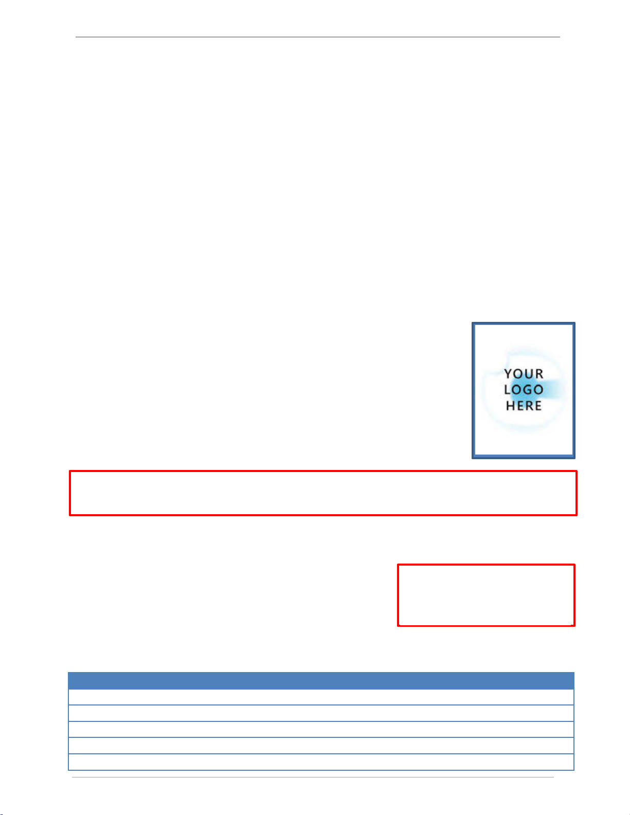
Boot Up Procedure
The RoosterTM does not have a power-on switch and will become energized as soon as
you plug it in. The RoosterTM boots to the screen depicted on the right, with a slot for
a custom logo. The boot screen is designed to support a custom image or logo file in
portable network graphic (.png) format with (240x320) dimensions. This feature must
be requested and is not setup for manual configuration.
Once the start procedure has completed, the Home screen will appear with two
system buttons and you will need to setup password-protected access tiers for
advanced system functions. This is explained in the “Access Tier Privileges” section
below.
You can reboot your RoosterTM Sensor100 at any time by pushing the hard “Home”and “Mute”Buttons
simultaneously until the Boot Screen reappears.
Access Tier Privileges: USER, EH&S & CERTIFIER
Users have the ability to customize their containment cabinets within
a defined set of options for each authorization level. There are three
levels of access to the RoosterTM: User, EH&S/Facility Manager and
Certifier. These are managed by logging in with a 4-digit numerical
passcode. The User access level does not require a passcode.
Access Privileges Defined
Function
Passcode Required
Adjust Alarm Volume
None
Alarm Latching Settings
EH&S, Certifier
Alarm Ringback Settings
EH&S, Certifier
Mute Live Alarm
None
Set Asset Tag
EH&S
Manufacturer default passcodes:
EH&S = 8377
Certifier = 6425

Rooster™Sensor100 USER MANUAL 62320MN000-A02
Rooster TM Sensor100 USER MANUAL 62320MN000-A02 10
Set Minimum Alarm Volume Threshold
EH&S, Certifier
Set Time / Clock Format
EH&S, Certifier
Toggle between Fahrenheit or Centigrade Temperature Units on Home Screen
None
Toggle between Metric or Imperial Air Velocity Units on Home Screen
None
Toggle ON/OFF Keypad Sounds
None
Unlatch Alarm
EH&S
Set/Change Passwords
To change or set a password, follow this GUI path to trigger the password change sequence:
Home> Settings>System>Advanced>Change Passwords
You will have to enter an EH&S or Certifier passcode to get access to the “Advanced” menu. To change either
the EH&S or Certifier passcode, you must first re-enter the old passcode. Please note that if you are authorized
to perform both EH&S and Certifier functions, you may set an identical passcode for both access tiers to make
logging in and accessing key functions easier.
Alarm Threshold Configuration
1) To set your alarm threshold, follow the menu path below :
Home> Settings>Thresholds>Adjust Thresholds
2) To set alarm thresholds, you will first have to define an alarm trip point and an alarm clear point.
The alarm trip point is the air velocity value that will trigger an alarm. The alarm clear point is the
air velocity value that will clear an alarm state. Once you have defined these values, the alarm will trip
and clear based on your settings. You may return to this menu at any time to adjust these values as
needed.
3) By default, no value is set to NSB (Night Setback) mode of operation. Depending on your application
or setup, you may not need to have an active alarm during night setback mode. You may choose,
however, to set a specific alarm trip and clear point for Night setback mode. You will first have to
define an alarm trip point and an alarm clear point. The alarm trip point is the air velocity value that
will trigger an alarm. The alarm clear point is the air velocity value that will clear an alarm state. Once
thresholds are assigned for night setback, you may choose to set your alarm as “audible” or “muted” in
the alarm controls menu below.:
Home> Settings>System>Alarms/Sound>Alarm Controls>Night Setback
4) To quickly glance at threshold settings, follow this menu path below:
Home> Settings> Thresholds>Threshold Info

Rooster™Sensor100 USER MANUAL 62320MN000-A02
Rooster TM Sensor100 USER MANUAL 62320MN000-A02 11
Alarm Troubleshooting
Is your alarm failing to sound or clear how you intended? You may need to verify that you have entered valid
threshold values. For both normal and NSB modes of operation, the “Alarm Trip” or “NSB Trip” point must be a
lower value than the “Alarm Clear” or “NSB Clear” point to properly trigger and clear an alarm.
The RoosterTM Sensor100 offers an array of customization options for alarm behaviors. In the following section,
we will provide a detailed overview on how to customize your alarm behavior to meet your particular needs and
preferences.
Alarm Controls
To provide our users with full customization of the alarm behaviors that are best suited for their facilities and
unique conditions, the RoosterTM Sensor100 allows authorized users (Certifier & EH&S) to set latching, ringback,
night setback, alarm delay and airflow resolution preferences.
Night SetBack
The RoosterTM Sensor100 supports Night Setback for energy savings and greater HVAC system integration
in building automation systems. Users can toggle between 3 modes of operation detailed below:
*This crescent moon icon [ ] will appear on the top portion of the home screen when Night Setback is active*
Home> Settings>System>Alarms/Sound>Alarm Controls>Night Setback
Night SetBack Modes
Definition
Audible
Enters Night Setback mode whenever relay is closed and audibly triggers an alarm
when airflow drops below NSB trip point. To adjust Night Setback alarm thresholds,
you must go to the Threshold menu and select “Adjust Thresholds”.
Muted
Enters Night Setback mode whenever relay is closed and triggers a muted alarm when
airflow drops below NSB trip point. (LED will still flash during an alarm event). To adjust
Night Setback alarm thresholds, you must go to the Threshold menu and select “Adjust
Thresholds”. This is the default setting.
Off
Disables Night Setback mode. Alarm does not enter Night Setback mode when relay is
closed.
Alarm Ringback
When an active alarm state is muted, ringback is a useful safety feature to remind the user that the muted alarm
is still active. Whenever there is an active alarm state, the red LED will flash for the entire duration of the alarm.
There are 7 ringback modes available:
Home> Settings>System>Alarms/Sound>Alarm Controls>Ringback
Settings
Definition
Off
Disables ringback. If an alarm is muted, the alarm remains muted for the entire duration of the
alarm event.
10s
A muted alarm will ringback audibly after 10 seconds if the unit is still in an active alarm state.
This is the default setting.*
30s
A muted alarm will ringback audibly after 30 seconds if the unit is still in an active alarm state.
1min
A muted alarm will ringback audibly after 60 seconds if the unit is still in an active alarm state.
5min
A muted alarm will ringback audibly after 5 minutes if the unit is still in an active alarm state.
10min
A muted alarm will ringback audibly after 10 minutes if the unit is still in an active alarm state.
60min
A muted alarm will ringback audibly after 60 minutes if the unit is still in an active alarm state.

Rooster™Sensor100 USER MANUAL 62320MN000-A02
Rooster TM Sensor100 USER MANUAL 62320MN000-A02 12
Backlight Dimming
Brightness is adjusted via the left and right arrows. Actual screen brightness adjusts immediately as
the setting is changed. The Enter button will save the brightness setting, and
cancel will leave the setting unchanged.
Auto-Dim Time resets a timer each time that the screen is pressed. Once that
particular amount of time has expired, the screen will dim. When the screen
is pressed again, the screen will return to its original brightness setting.
The dimmest setting will not allow the screen to turn completely dark, instead
just enough to still be readable. Dim times are [1, 2, 5, 10, 60] minutes, with an
“Off” setting, and a default time of 10 minutes initially.
Home> Settings>System>Brightness
Latch Alarm
Alarm latching is a useful feature to indicate that an alarm state was triggered even if the device is no longer in
an active alarm state. This could occur, for example, when a user has stepped away from the workstation. When
latching is activated “ON”, a yellow banner will display beneath the velocity and temperature readings on the
home screen to indicate that a low airflow event has occurred. If the latch alarm setting is set to “Password”
mode, an EH&S passcode must be entered to unlatch this alarm. If the Latch alarm setting is set to “ON”,
simply tap the banner to disable the alarm. Switching the latch state to “OFF” disables this feature entirely.
Home> Settings>System>Alarms/Sound>Alarm Controls>Latch Alarm
Alarm Delay
To account for hysteresis, users can define the amount of time that the RoosterTM Sensor100 has to achieve
continuous safe velocity readings before the alarm state is cleared and continuous unsafe velocity readings
before an alarm is triggered. This is called Alarm Delay.
Alarm Delay
Definition
1s
Alarm is cleared after 1 second if velocity readings are above the alarm clear threshold.
Alarm is triggered after 1 second if velocity readings are below the alarm trip threshold. This
is the default setting.
2s
Alarm is cleared after 2 seconds if velocity readings are above the alarm clear threshold.
Alarm is triggered after 2 seconds if velocity readings are below the alarm trip threshold.
5s
Alarm is cleared after 5 seconds if velocity readings are above the alarm clear threshold.
Alarm is triggered after 5 seconds if velocity readings are below the alarm trip threshold.
10s
Alarm is cleared after 10 seconds if velocity readings are above the alarm clear threshold.
Alarm is triggered after 10 seconds if velocity readings are below the alarm trip threshold.

Rooster™Sensor100 USER MANUAL 62320MN000-A02
Rooster TM Sensor100 USER MANUAL 62320MN000-A02 13
Startup Delay
The startup delay prevents an alarm from triggering until the workstation and ventilation systems have fully
powered up and are operational. Refer to chart on next page for further definitions.
Alarm Delay
Definition
30s
Alarm is paused for 30 seconds on power up.
1 min
Alarm is paused for 1 minute on power up.
2 min
Alarm is paused for 2 minutes on power up.
5 min
Alarm is paused for 5 minutes on power up.
Duct Size
Volumetric flow can be displayed on the home screen for the
RoosterTM Sensor100. In order to set this up, enter the duct
diameter screen from the settings menu. Select the shape of
the duct, and the diameter (in cm).
Once the duct diameter is entered, the user is then able to
cycle between fpm, m/s, and cfm on the home screen.
Home>Settings>Duct Size
Airflow Resolution
For advanced users, displayed velocity units can be configured to display in an alternate resolution.
The default resolution for units is 1 fpm and .01 m/s respectively, however, for users who prefer a more
uniform readout, this can be configured up to 5 fpm or .05 m/s.
Home>Settings>System>Airflow Settings>Airflow Resolution
Airflow Resolution
Definition
1 fpm
Displayed units in FPM are rounded to 1 fpm. This is the default setting.
2 fpm
Displayed units in FPM are rounded to 2 fpm.
5 fpm
Displayed units in FPM are rounded to 5 fpm.
.01 m/s
Displayed units in m/s are rounded to .01 m/s. This is the default setting.
.02 m/s
Displayed units in m/s are rounded to .02 m/s.
.05 m/s
Displayed units in m/s are rounded to .05 m/s.
Airflow Sensitivity
This setting smooths airflow readings by applying a filter that determines “sensitivity” of readings.
Home>Settings>System>Airflow Settings>Sensitivity
Sensitivity
Definition
Low
Decreases filtration effect, resulting in greater fluctuation of readings.
Med
Default setting. Filtration effect stabilizes readings.
High
Increases filtration effect, providing smoother readings.

Rooster™Sensor100 USER MANUAL 62320MN000-A02
Rooster TM Sensor100 USER MANUAL 62320MN000-A02 14
I/O Polarity
For advanced users, it may be helpful to toggle relay and input nodes from N/C to N/O. Consult diagram below
for further information.
Home>Settings>System>Advanced>I/O Polarity
DAC Output
The RoosterTM Sensor100 has DAC Output enabled, with correspondence to air velocity.
There are four user selectable ranges to choose from, which the user will connect to pins 7 & 8 on the rear
panel’s 8-position “Outputs” Connector:
o 0-5 VDC
o 0-10 VDC
o 0-20 mA (not implemented yet)
o 4-20 mA (not implemented yet)
Home>Settings>System>Advanced>Analog Out

Rooster™Sensor100 USER MANUAL 62320MN000-A02
Rooster TM Sensor100 USER MANUAL 62320MN000-A02 15
USB Field Upgrade Procedure
Procedure to field upgrade Rooster TM Sensor100 Operating System
You will need: USB thumb drive with new firmware “Rooster.bin”
RoosterTM Sensor100
Procedure:
1. Remove power from the RoosterTM Sensor100 by unplugging power supply.
2. Insert USB thumb drive into left side of RoosterTM Sensor100.
3. Depress and hold “Home” button, then re-apply power to your unit. (Hard Home button must be
depressed while RoosterTM powers up to enter the firmware update sequence)
4. After ~3 seconds, release Home button. After 10 seconds, the LED on the front of the RoosterTM
will light and the unit will boot up with new Firmware.
5. When you have completed the Factory Reset Procedure, navigate to the info [ ] screen from
home to validate that your new firmware version was properly installed. The date of the firmware
release –listed next to “firmware” - should have changed to the most current build. If this is not
the case, repeat steps 1-6 again.
Factory Reset Procedure
The Master Reset will return the Rooster Sensor100 to its default alarm & input/output settings. Time and
date will be preserved during a factory reset. The following Factory Reset Procedure can be done at any
time upon system reset to restore default settings and passwords.
1. After following the above steps, when the 1st information screen displays, momentarily press the
“Mute” key.
2. The “Enter Factory Password” screen will display. Factory Password is “5878” and cannot be
changed.
3. Factory Menu will display. Depress “Reset to Factory Defaults”
Factory-default certify password is “6425”

Rooster™Sensor100 USER MANUAL 62320MN000-A02
Rooster TM Sensor100 USER MANUAL 62320MN000-A02 16
GUI Map
WARRANTY
The RoosterTM Sensor100 is warranted to be free from defects in workmanship and materials for a period of one
(1) year from receipt. Degree Controls will at its option replace or repair defective parts within the warranty
period. Damage resulting from misuse, wear and tear, and tampering is not covered by the warranty.
Table of contents
Popular Accessories manuals by other brands

Johnson Controls
Johnson Controls NS8000 Series installation guide

Tasseron
Tasseron Q-Duct SAFE installation instructions

Aromateca
Aromateca Spark user manual

BaiYou Electronic
BaiYou Electronic BY213-C021-W installation instructions

EMX Industries
EMX Industries OWL instruction manual

Elenco Electronics
Elenco Electronics AK-300 Instruction & assembly manual

ROSE DISPLAYS
ROSE DISPLAYS ANOSKYBOX-TOP LOADING 3 WAY manual

FAAFTECH
FAAFTECH FT-RC-AUD10 installation manual

STI
STI STI-34601 instructions

Distech Controls
Distech Controls EC-Multi-Sensor-BLE installation guide

Controlli
Controlli S A Series Mounting instructions

SilverBack
SilverBack B2315W owner's manual