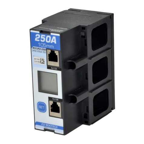
ROOTECH Accura 2350-3P-250A-105 Use and care manual

ACCURA 2300S/2350
Distribution Panel Digital Power Meter/Power Measuring Module
Actually makes possible enterprise energy management
Communication User Guide[English]
Revision 1.41 2015/07/20

Distribution Panel Digital Power Meter
Accura 2300S
Accura 2300S rear view
Three Phase Power Measuring Module
Single Phase Power Measuring Module
Accura 2350-3P-250A-105 TM-3P-105 Accura 2350-1P-250A-105 TM-1P-105
Accura 2350-3P-125A-90 TM-3P-90 Accura 2350-1P-125A-60 TM-1P-60
Accura 2350-3P-100A-75 TM-3P-75L Accura 2350-1P-100A-50 TM-1P-50L
Accura 2350-3P-60A-75 TM-3P-75 Accura 2350-1P-60A-50 TM-1P-50
Accura 2350-3P-CT5A-75

Split-core Three Phase
Power Measuring Module
Split-core Single Phase
Power Measuring Module
Split-core Single Phase Single Hole
Power Measuring Module
Accura 2350-3PSC-250A-105 Accura 2350-1PSC-250A-105 Accura 2350-1PSCSH-800A
Accura 2350-3PSC-125A-90 Accura 2350-1PSC-125A-60 Accura 2350-1PSCSH-630A
Accura 2350-3PSC-60A-75 Accura 2350-1PSC-60A-50 Accura 2350-1PSCSH-400A


Accura 2300/2350 Communication User Guide
Notice
ⓒ2011 Rootech Inc. All Rights Reserved Page 5
Notice
Symbol
Caution
Indicates the presence of dangerous voltage which can cause severe injury or death
to persons if proper precautions are not followed.
Warning
Alerts the user to the presence of hazards which can cause somewhat injury to
persons, damage to property or damage to the device itself, if proper precautions
are not followed.
Note
Indicates the user’s attention to installation, operating and maintenance
instructions.
Indicates alternative voltage or current.
Indicates direct voltage or current.
Installation Considerations
Installation and operation of Accura 2300S/2350 should be performed only by qualified, competent
personnel that have appropriate training and experience with high voltage and current devices.
Caution
Failure to observe the following instructions may result in severe injury or death.
During normal operation of the Accura 2300S/2350, hazardous voltages are present on its terminal strips of
voltages input and power.
Standard safety precautions are followed while performing any installation or service work[removing PT fuses,
shorting CT secondaries, etc].
Do not access to terminal strips of the Accura 2300S/2350 after installation.

Notice
Accura 2300/2350 Communication User Guide
Page 6 ⓒ2013 Rootech Inc. All Rights Reserved
Warning
Observe the following instructions, or permanent damage to the meter may occur.
Do not apply Accura 2300S/2350 to voltages and currents that exceed Input ratings of PT and CT
Limitation of Liability
Rootech Inc. reserves the right to make changes in the device specifications shown in this User Guide
without notice. Rootech Inc. advises customers to obtain the latest specifications of device before giving
orders to confirm that the information being relied on by the customer is up to date.
Inc. applications assistance, customer’s system design, or infringement of patents or copyrights of
third parties by or arsing from the use of devices described herein.
Except to the extent prohibited by applicable law, under no circumstances shall Rootech Inc. be liable
for consequential damages sustained in connection with said product and Rootech Inc. neither
assumes nor authorizes any representative or other person any obligation or liability other than such
as is expressly set forth herein.
Accura EMeter, Accura 2300/2350, Accura 2300S/2350, Accura 2500, Accura 3300S/3300, Accura
3500S/3500, Accura 3550S/3550, Accura 3700, Accura 5500, Accura 7500 are trademarks of
Rootech Inc.
The information contained in this document is believed to be accurate at the time of publication,
however, Rootech Inc. assumes no responsibility for any errors which may appear here and reserves
the right to make changes without notice.

Accura 2300S/2350 Communucation User Guide
Standard Compliance
ⓒ2013 Rootech Inc. All Rights Reserved Page 7
Standard Compliance
MEASURING EQUIPMENT
35DX
E258934
MSIP-REM-RTE-ACCURA 2300S
QMS-1347 KAB-QC-09

Warranty Information
Accura 2300S/2350 Communication User Guide
Page 8 ⓒ2013 Rootech Inc. All Rights Reserved
Warranty Information
For products and software that are sold or licensed by Rootech Inc. during the period from the date
of receipt by you until the present, Rootech warrants only to the original purchaser
The purchased products shall be substantially free from material defects in material and workmanship
by Rootech for two years from the date receipt by you.
The software itself is provided “as is”without any warranty of any kind.
Limitation of Warranty
These limited Warranties shall not apply to any product that has been subject to alteration, accident,
misuse, abuse, neglect or failure to exactly follow Power Measurement's instructions for operation and
maintenance.
In order for the original purchaser to make a claim under the warranties described above, the original
purchaser must promptly contact Rootech headquarter. After receiving such notice, Rootech may either
in Rootech’s sole discretion, examine the product at the original purchaser’s site or issue shipping
instructions to the original purchaser to return the relevant product to Rootech for examination at the
original purchaser’s expense, transportation charges prepaid.
If after examining the product Rootech reasonably confirms that such examined product does not
meet the warranties, then the original purchaser’s sole remedy and Rootech’s sole obligation or
liability shall be, at Rootech’s option, to repair, replace or refund the price paid for that product.
Regardless of whether any remedy set forth herein fails of its essential purpose, except to the extent
the following limitation is prohibited by applicable law, Rootech shall not, in any event or under any
legal claim or theory, be liable to the original purchaser or any other person or entity for special,
indirect, incidental, punitive, liquidated, special or consequential damages whatsoever with respect to
any purchased product, including, without limitation, business interruption, loss of use, profit or
revenue, even if Rootech has been advised of the possibility of such damages. To the extent that a
limitation or exclusion of consequential damages are prohibited by app
licable law, then Rootech’s liability shall be limited to twice the amount of the relevant purchased
product.
Rootech shall not be liable for any claim- other than a claim solely for the breach of one of the above

Accura 2300S/2350 Communication User Guide
Warranty Information
ⓒ2013 Rootech Inc. All Rights Reserved Page 9
warranties that is made in accordance with the above described procedures- made by the original
purchaser, its employees, agents, or contractors for any loss, damage, or expense incurred due to,
caused by, or related to any purchased product
Any technical assistance provided by Rootech's personnel or representatives in system design shall be
deemed to be a proposal and not a recommendation. The responsibility for determining the feasibility
of such proposals rests with the original purchaser and should be tested by the original purchaser.
It is the original purchaser’s responsibility to determine the suitability of any product and associated
documentation for its purposes. The original purchaser acknowledges that 100% "up" time is not
realizable because of possible hardware or software defects. The original purchaser recognizes that
such defects and failures may cause inaccuracies or malfunctions.
Only the terms expressed in these limited Warranties shall apply and no distributor, corporation or
other entity, individual or employee of Rootech or any other entity is authorized to amend, modify or
extend the Warranties in any way.

Revision History
Accura 2300S/2350 Communication User Guide
Page 10 ⓒ2013 Rootech Inc. All Rights Reserved
Revision History
The following versions of the Accura 2300S/2350 Communication User Guide have been released.
Revision
Date
Description
Revision 1.40 2015. 05. 13 - Modified by separation of communication manual
- Range symbol, change of ~ to –(hyphen)
- Standard compliance image revised.
Revision 1.41 2015. 07. 20 Standard compliance updated
Rootech
102-611 Digital Empire2, Sinwon-ro 88
Yeongtong-gu, Suwon, Gyeonggi-do, Korea
Tel. 031-695-7350 Fax. 031-695-7399
Website www.rootech.com
E-mail address supervisor@rootech.com

Accura 2300S/2350 Communication User Guide
Contents
ⓒ2013 Rootech Inc. All Rights Reserved Page 11
Contents
Chapter 1 Modbus Protocol of Accura 2300S..................................................................................... 16
Modbus Protocol Overview ..............................................................................................................16
Modbus Protocol .......................................................................................................................16
Modbus RTU Protocol ................................................................................................................16
Modbus TCP Protocol ................................................................................................................16
Modbus Packet Structure ..................................................................................................................17
Modbus RTU Packet Structure.....................................................................................................17
Modbus TCP Packet Structure .....................................................................................................18
Accura 2300S Modbus Support........................................................................................................19
Unit ID (Only for Modbus TCP)...................................................................................................19
Function Code...........................................................................................................................19
Multiple Connection Policy .........................................................................................................20
Access End Policy.......................................................................................................................20
Accura 2300S Function Code Packet Structure ..................................................................................21
Function 3 [03h] : Read Holding Registers ..................................................................................21
Function 6 [06h] : Write Single Register ......................................................................................23
Function 16 [10h] : Write Multiple Registers ................................................................................24
Function 101 [65h] : Read Multi-Block Registers..........................................................................26
Chapter 2 Modbus Map of Accura 2300S.......................................................................................... 29
Modbus Map Overview....................................................................................................................29
Data Format .............................................................................................................................31
Register Access Data Features ....................................................................................................32
System Information Category ...........................................................................................................35
Accura 2300S System information..............................................................................................35
Accura 2350 System information................................................................................................35
Detailed Map for Accura 2350 System Information .....................................................................36
Setup Category ...............................................................................................................................38
Remote Setup Unlock.................................................................................................................38
General Setup...........................................................................................................................38
Network Setup ..........................................................................................................................39
Network Time Protocol (NTP) Setup ............................................................................................40
Measurement Setup...................................................................................................................41
User Interface Setup ..................................................................................................................43

Contents
Accura 2300S/2350 Communication User Guide
Page 12 ⓒ2013 Rootech Inc. All Rights Reserved
Digital Output (DO) Setup of Accura 2300S ...............................................................................44
Dip / Swell Setup.......................................................................................................................46
ID Setup of Accura 2350 Module ...............................................................................................47
Module Management Setup of Accura 2350 Module...................................................................48
General Setup of Accura 2350 Module ......................................................................................50
Extended Setup of Accura 2350 Module .....................................................................................50
Detailed Map for Accura 2350’s General Setup –3P , 1P Module ...............................................51
Detailed Map for Accura 2350’s General Setup –GAS Module ...................................................53
Detailed Map for Accura 2350’s General Setup –GW Module ....................................................54
Detailed Map for Accura 2350’s General Setup –TEMP Module..................................................55
Detailed Map for Accura 2350’s Extended Setup –GW Module...................................................56
Detailed Map for Accura 2350’s Extended Setup –DO Module ...................................................58
Detailed Map for Accura 2350’s Extended Setup –IDC Module...................................................60
Detailed Map for Accura 2350’s Extended Setup –VDC Module..................................................62
Energy Level Setup of Accura 2350 - 3P , 1P Module ..................................................................64
Aggregation Setup.....................................................................................................................64
Group Setup of Accura 2350-1P Module....................................................................................66
Voltage Failure Detection Setup..................................................................................................67
Modbus Serial Communication Setup.........................................................................................67
Current Event Setup...................................................................................................................68
Temperature Event Setup............................................................................................................69
Leakage Current Event Setup .....................................................................................................69
Summer Time Setup ..................................................................................................................70
User-defined Expression Setup ...................................................................................................71
Control Category ............................................................................................................................74
Remote Control Unlock..............................................................................................................74
Measurement Control................................................................................................................74
User Interface Control ...............................................................................................................75
Digital Input / Digital Output Control of Accura 2300S ...............................................................75
Extended Control of Accura 2350 Module ..................................................................................77
Detailed Map for Accura 2350’s Extended Control –GW Module................................................77
Detailed Map for Accura 2350’s Extended Control –DO Module ................................................78
Measurement Data Category ...........................................................................................................80
Basic Measurement Data ...........................................................................................................80
Accura 2300S Voltage Data.......................................................................................................87
Accura 2350-3P Module Data ...................................................................................................88

Accura 2300S/2350 Communication User Guide
Figures
ⓒ2013 Rootech Inc. All Rights Reserved Page 13
Accura 2350-1P Module Data ...................................................................................................91
Accura 2350-GAS Module Data ................................................................................................92
Accura 2350-GW Module Data .................................................................................................93
Accura 2350-DO Module Data..................................................................................................94
Accura 2350-IDC Module data..................................................................................................94
Accura 2350-VDC Module data .................................................................................................95
Accura 2350-TEMP Module data................................................................................................96
Accura 2300S Voltage Max/Min Data with time-stamp................................................................97
Accura 2350-3P Module Max/Min Data with time-stamp ............................................................99
Accura 2350-1P Module Max/Min Data with time-stamp ..........................................................104
Accura 2350-GAS Module Max/Min Data with time-stamp .......................................................106
Accura 2350-IDC Module Max/Min Data with time-stamp ........................................................107
Accura 2350-VDC Module Max/Min Data with time-stamp .......................................................108
Accura 2350-TEMP Module Max/Min Data with time-stamp ......................................................109
Voltage Harmonics Data of Accura 2300S................................................................................111
Current Harmonics Data of Accura 2350 - 3P , 1P Module .......................................................111
Voltage Waveform Data of Accura 2300S.................................................................................112
Current Waveform Data of Accura 2350 - 3P , 1P Module ........................................................112
Measurement Event Data Category ................................................................................................113
Measurement Event Data.........................................................................................................113
Detailed Map for Measurement Event Data...............................................................................115
Event Clear .............................................................................................................................120
Chapter 3 Modbus Map Application ............................................................................................... 121
Register Addressing .................................................................................................................121
Data Format ...........................................................................................................................121
Endian....................................................................................................................................121
Data Collection Check: Address Error and Endian Error ............................................................122
Setup of device..............................................................................................................................123
Remote Setup Unlocking..........................................................................................................123
Remote Setup Locking..............................................................................................................123
Control of device...........................................................................................................................124
Remote Control Unlocking.......................................................................................................124
Remote Control Locking...........................................................................................................124
Collection of Measurement Data....................................................................................................125
Flowchart................................................................................................................................125
Selection of Aggregation..........................................................................................................127

Contents
Accura 2300S/2350 Communication User Guide
Page 14 ⓒ2013 Rootech Inc. All Rights Reserved
Selection of Buffer Index ..........................................................................................................128
Fetch of Measurement Data .....................................................................................................128
Validity Check and Collection of Voltage Data ..........................................................................128
Validity Type Check and Collection of Module Data...................................................................129
APPENDIX A Sample of Modbus RTU Packet..................................................................................... 130
Request Packet ........................................................................................................................130
Response Packet......................................................................................................................130
APPENDIX B Sample of Modbus TCP Packet ..................................................................................... 131
Request Packet ........................................................................................................................131
Response Packet......................................................................................................................131
APPENDIX C CRC-16[Modbus] Algorithm ........................................................................................ 132
CRC Table Preparation ............................................................................................................132
CRC Generation......................................................................................................................132
APPENDIX D User-defined Formula Method ..................................................................................... 133
Formula Components..............................................................................................................133
Format of Module Data ...........................................................................................................133
Format of Number Data ..........................................................................................................134
Format of Normal Operator.....................................................................................................134
Format of Casting Operator.....................................................................................................135
Format of End-of-Stream .........................................................................................................135
Y= User-defined Formula Example ..........................................................................................135

Accura 2300S/2350 Communication User Guide
Figures
ⓒ2013 Rootech Inc. All Rights Reserved Page 15
Figures
Fig 1.1 Private holding register for individual connection.............................................................20
Fig 2.1 Read access of holding register.......................................................................................32
Fig 2.2 Write access of holding register ......................................................................................32
Fig 2.3 Private Read access of holding register : Read Access ......................................................33
Fig 2.4 Private Read access of holding register : Read Parameter.................................................33
Fig 2.5 Private Write access of holding register : Write Parameter.................................................34
Fig 2.6 Private Write access of holding register : Write Access......................................................34
Fig 2.7 Aggregation of measured data.......................................................................................80
Fig 3.1 Flowchart of measurement data collection.....................................................................126

Chapter 1 Modbus Protocol of Accura 2300S
Accura 2300S/2350 Communication User Guide
Page 16 ⓒ2013 Rootech Inc. All Rights Reserved
Chapter 1 Modbus Protocol of Accura 2300S
Modbus Protocol Overview
In this chapter, basic explanation for Modbus RTU protocol and Modbus TCP protocol used in Accura
2300S is provided. Specific definition for Modbus protocol, Modbus RTU protocol and Modbus TCP
protocol is explained on www.modbus.org
Modbus Protocol
Modbus protocol is unrelated to data transmission method and application protocol to compose
and interpret data. Master transmits request packet to address of slave device(single or broadcast)
corresponding to format defined by Modbus protocol, and transmits data to request and error
checking code corresponding to the definition of function code. Response of slave device is also
composed using Modbus protocol. This performs the function confirming the operation is performed
and includes the data corresponding to the requested result and error checking code. If the error
generates when the message is received or the operation responding to the request can not be
performed, error message is composed to the response.
Modbus RTU Protocol
Modbus RTU protocol is one of the Modbus protocol to operate in the serial communication
environment as RS-485 or RS-232. This protocol classifies each device through device ID and confirms
error using CRC. Multiple connection through one serial communication channel is not allowed.
Modbus TCP Protocol
Modbus TCP protocol resembles Modbus RTU protocol but it is improved to operate more effectively
under TCP/IP level. Main function of TCP/IP is to guarantee the perfect receive about the all packets
that the address and channel are perfect.
TCP/IP is only the transmission protocol. So it does not define what the data means or how to interpret.
This is the role of application protocol and Modbus protocol is included in this.
Modbus TCP protocol communicates as TCP/IP network standard by sending data at Modbus packet
structure between devices that are compatible with ethernet environment. Modbus TCP protocol does
not include Modbus checksum as it is included in TCP frame.
The sequence of request and response may not be the same. Also the gap between packets is not
needed. Furthermore, multiple connection is also available as it operates on TCP protocol. The
maximum connection number is decided corresponding to individual device.

Accura 2300S/2350 Communication User Guide
Chapter 1 Modbus Protocol of Accura 2300S
ⓒ2013 Rootech Inc. All Rights Reserved Page 17
Modbus Packet Structure
Modbus RTU Packet Structure
Packet structure of Modbus RTU protocol is as followed.
Device Address Function Code Data CRC
1 bytes 1 byte n bytes 2 bytes
The meaning of each field is as followed.
Fields
Description
Device Address Device address is used to classify the each slave device and has range
from 1 to 247.
Function Code
Means which operation
to do at slave when request is transmitted from
master to request.
In normal response situation, uses function code as it is written at request.
In response situation for error, uses function code as function code of
response by adding 80h.
Data Data field differs corresponding to function code.
CRC
As the field to check error, uses code which is created
by using
CRC(Cyclical Redundancy Check). CRC field checks all message
contents and uses CRC-16 algorithm. This is specifically described in
Appendix C.

Chapter 1 Modbus Protocol of Accura 2300S
Accura 2300S/2350 Communication User Guide
Page 18 ⓒ2013 Rootech Inc. All Rights Reserved
Modbus TCP Packet Structure
Modbus TCP protocol packet structure is as follwed.
Modbus TCP Header Function
Code
Data
Transaction ID Protocol ID Length Unit ID
2 bytes 2 bytes 2 bytes 1 byte
1 byte
n bytes
The meaning of each field is as followed.
Fields
Description
Transaction ID This field is an ID for finding the pair of transaction among some
messages in same TCP connection without waiting the previous response.
The sequence of request and response is not the same.
Normally this value increases by 1 in each request and response, and
circulates in the range of 0000h –FFFFh.
At the time of response, transaction ID of request is used without
changing.
Protocol ID This range is always fixed as 0 and other values are reserved.
Request and response are all applied.
Length R
egister is accessed as address starting from 0. So register address is
calculated by subtracting 1 from the register number of Modbus map.
This field is the
byte number of remained field and is the length that adds
up unit ID, function code and data field.
Unit ID 1 This field that other slave devices are connected to Modbus TCP device and
to communicate in a lump, is used to classify each slave.
Function Code Means which operation
to do at slave when request is transmitted from
master to request.
In normal response situation, uses function code as it is written at request.
In response situation for error, uses function code as function code of
response by adding 80h.
Data Data field differs corresponding to function code.
1This field is fixed as 1 in Accura 2300S. Accura 2300S brings all measurement data with connected Accura
2350 through internal communication.

Accura 2300S/2350 Communication User Guide
Chapter 1 Modbus Protocol of Accura 2300S
ⓒ2013 Rootech Inc. All Rights Reserved Page 19
Accura 2300S Modbus Support
Unit ID (Only for Modbus TCP)
This field is fixed as 1 in Accura 2300S. Accura 2300S periodically collects all measurement data
of connected Accura 2350 through internal communication. So all data of Accura 2350s is collected
through Accura 2300S.
Function Code
Function codes that Accura 2300S supports are as followed.
Function code
Decimal
[Hexadecimal]
Name
Description
3 [03h] Read Holding Registers
1
Reads holding register 1-65536 data of slave device
Request message is described with the quantity of register to start
reading and to read.
As register is accessed as address starting from 0, register 1-
16 is
accessed as 0-15 address.
6 [06h] Write Single Register Writes the value on one register of the holding registers of 1-65535.
Request message is described with
the holding register and data to
write. As register is
accessed as address starting from 0, register 1 is
accessed as 0 address.
16 [10h] Write Multiple Registers Writes the values on several continuous registers
among holding
registers 1-65536 of slave device.
Request message is described with the register to start writing, register
quantity and data.
As register is accessed as address starting from 0,
register 1-16 is accessed as 0-15 address.
101 [65h] Read
Multi-block Registers
This function code is user-defined function code. As this is the only one
read packet, it can read one or several holding register blocks. Each
holding register block is the package of continued registers. As this
function code can read data of registers
spreaded for large range, this
has an effect of decreasing a communication overhead. This function
code is provided
only at Modbus TCP protocol
.
Details are described in packet structure.
1Holding register is 16-bit (2-byte) word.

Chapter 1 Modbus Protocol of Accura 2300S
Accura 2300S/2350 Communication User Guide
Page 20 ⓒ2013 Rootech Inc. All Rights Reserved
Multiple Connection Policy
Accura 2300S provides 17 simultaneous-connections of (TCP16, RTU). Each connection is
independent.
Each connection can perform unique work by using its independent private holding register.
Holding register of which the connection feature on Modbus map is PR (private read) or PRW (private
read / write), is assigned individual private holding register per each connection. Therefore even if
the value of private register is changed at certain connection, value of private register of other
connection is not changed.
Fig 1.1 Private holding register for individual connection
Master A
device
working
parameters
Modbus connection 1 PRW private holding registers
Accura 2300S
private holding registers
Master B
Modbus connection 2 PRW
Modbus connection 3 PRW
Same register numbers
application & fetch
application & fetch
application & fetch
Access End Policy
Accura 2300S ends Modbus TCP protocol connection for the following cases.
When connected client requests connection ending or forced ending happened.
When 1 minute(up to App 1.77 version) or 10 minutes(from App 1.78 version) passes without
request after the connection.
When protocol of Modbus TCP packet is not 0.
When the request for function code which is not supported is received.
This manual suits for next models
19
Table of contents
Other ROOTECH Control Unit manuals
Popular Control Unit manuals by other brands

Ricoh
Ricoh Aficio 700 operating instructions

Moeller
Moeller XIOC AWB2725-1452GB Hardware and engineering

VAT
VAT 244 Series Installation, operating, & maintenance instructions

Infineon
Infineon AIROC CYW20822-P4TAI040 manual

Hitachi
Hitachi HX-RIO3 Series user manual

VAT
VAT 010 Series Installation, operating, & maintenance instructions