K-20394
..
DISCHARGE
-~--
UNLOADING VALVE
DISCHARGE SNUBBER
~
ROVIDE
CONNECTIONS FOR
THERMOMETERS
AND PRESSURE OR
-
~~~~U~N~~?SEcSH~~~~~
TO
BLOWER
IPRESSURE
RELIEF
VALVE
\r
~
CHECK VALVE
~~~':t=6
CROSS
''-,L
FLEXIBLE
CONNECTORS
i_
ALTERNATE
ARRANGEMENT
OF
INLET
DRY
TYPE
INLET
FILTER
[
INLET
CLEANER-
SILENCER
INLET
SILENCER
--
_
Whispair blowers normally have aflattened bulge
on
one side of the cylinder with apipe connection extending
from it, as shown
in
Figure
1.
These units must be driven
with the correct rotation
to
make this connection
the
discharge. Figure 2shows
the
standard
drive shaft
locations as viewed from
the
drive end, and
the
correct
counterclockwise direction
of
rotation.
For
special con-
struction (drive shaft
at
the
top
or
right), correct rotations
would be opposite or clockwise. An arrow near
the
shaft
indicates
the
rotation
to
be used. Some few blowers
(1701,
1702,1704,1707)
do
not have cylinder bulge. These may be
operated in either direction, as necessary
to
produce
discharge
at
the more convenient connection.
Piping should
be
accurately
squa~ed
with
the
blower,
supported independently, and sized no smaller than
the
connections
on
the
blower. Use only clean, new pipe and
make certain
it
is free
of
scale, cuttings, weld beads,
dirt
or
any
other
foreign material. To guard against damage
to
blower, especially when an inlet filter is not used, install a
screen of
16
mesh backed with
hardware
cloth
at
or
near
the
inlet opening. Make provisions
to
clean
the
screen of
collected debris
after
afew hours operation, and
periodically thereafter. Install an inlet filter in dusty or
sandy locations.
Figure
3shows atypical complete installation
of
blower and accessories where
quietest
operation is wanted.
Note
the
absence of
throttle
or shut-off valves in either
dishcarge or intake piping.
If
it
is possible for air flow
to
be
cut off in either
of
these
lines, make provisions
to
add a
pressure
and/or
vacuum relief valve as discussed
under
OPERATING CHARACTERISTICS.
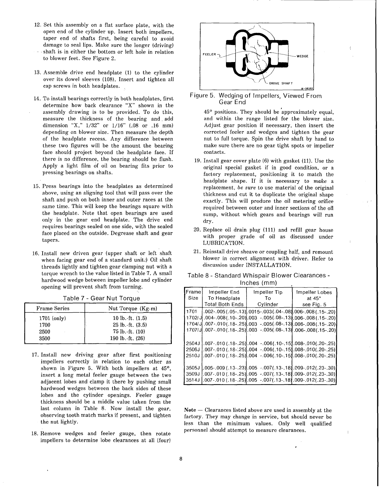
Figure 3. AComplete Blower Installation, With
Alternate Inlet Arrangement
In
some installations
it
may be desirable
to
use only an
inlet silencer-cleaner supported directly from
the
blower
connection. This is shown as an
alternate
arrangement
in
Figure
3.
Weight
must
be
kept
to
aminimum
to
prevent
blower casing distortion when
the
inlet is
on
the
side.
Ablower may be driven by direct coupling
to
the
driver, or by V-belt
to
obtain
other
speeds within
the
approved range. Refer
to
LIMITATIONS before selecting
the
drive speed. Also, be
sure
to
arrange for suitable
protective guards as discussed in PRECAUTIONS.
Lubricated couplings
are
the
preferred type,
but
Lovejoy Type Lor similar non-lubricated
type
may also be
used. Coupling halves
must
correctly fit blower and driver
shafts, so
that
only light
tapping
is required
to
install each
half. The two shafts
must
be as accurately aligned as
possible, both horizontally and vertically,
to
limit operating
strain on either shaft.
Proper
gap between coupling halves
must
be established with
the
motor
armature
on
its
electrical center. This will minimize
the
chance for end
thrust
on
the
blower shaft.
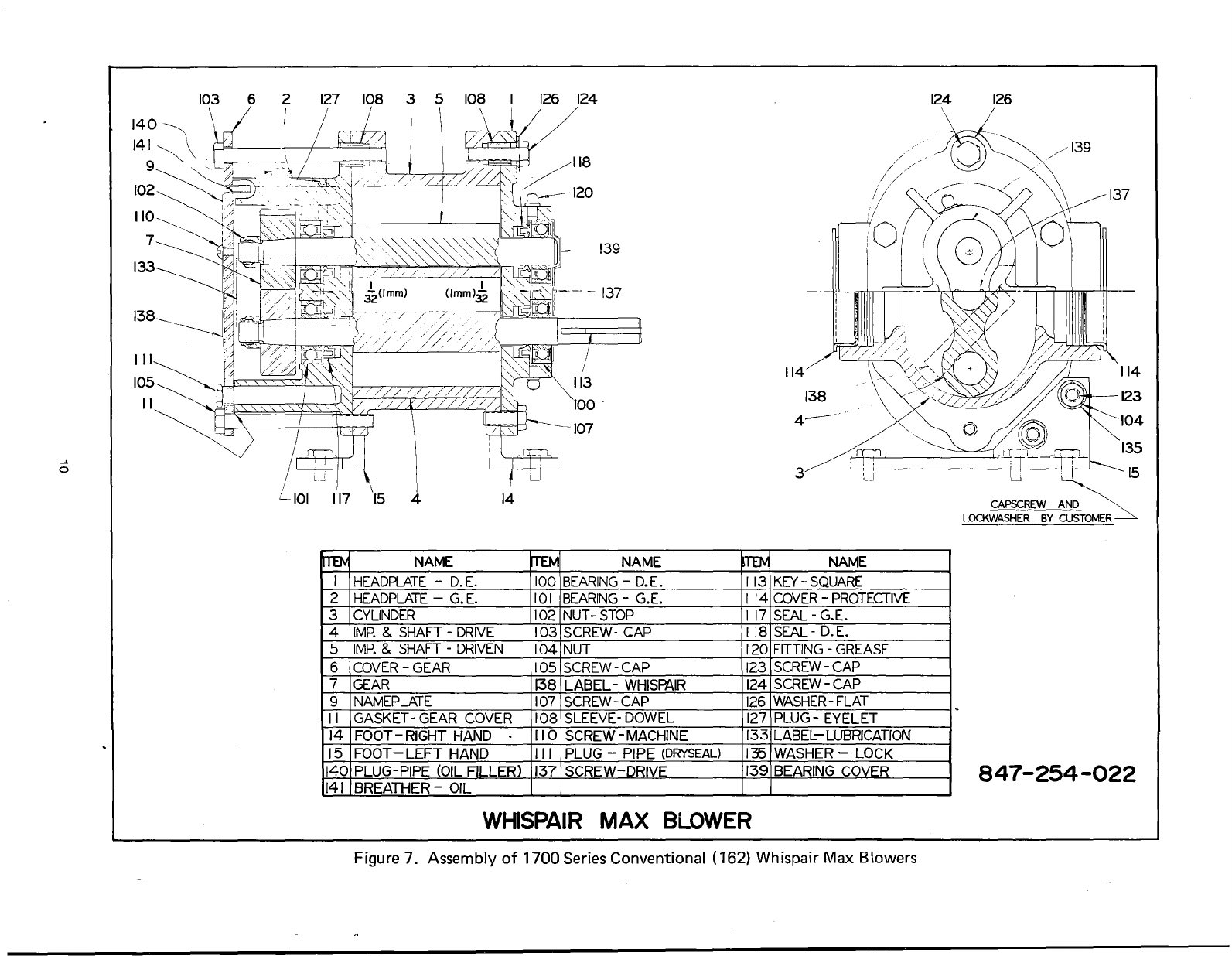
Figure
2.
Rotation and Discharge For Standard
Blower
t0
6.
Rotate
drive shaft
three
or four revolutions every
two weeks.
7.
Prior
to
startup,
remove flange covers
on
both inlet
and discharge and inspect internals
to
insure
absence of
rust,
check all internal clearances. Also,
at
this time, remove
gear
cover and inspect
gear
teeth
for
rust.
Install blower
in
aprotected indoor location, if
possible. However, an unprotected outdoor installation will
be satisfactory if correct lubrication for expected
temperatures
is provided.
Just
before
starting
the
installation, remove plugs
or
covers from inlet and
discharge connections. Inspect for
dirt
or
foreign objects
inside
the
blower,
then
turn
dirve shaft by hand
to
make
sure
that
it
rotates
freely.
Mount blower in alevel position. Use of arigid, solidly
supported, smooth flat plate is recommended. Make
sure
blower feet
rest
evenly
on
the
plate before fastening down.
Twisting
or
cramping
the
blower in mounting will cause
impeller contact and binding during operation.
On
blowers
having
two
feet, loosening
the the
screws (Item
123)
into
the headplate flanges should permit adjusting
the
feet for
even contact with
the
plate. Then fasten both feet
to
the
plate with screws and lockwashers, and
retighten
the
headplate screws carefully.
On
blowers with four feet, this
procedure may not be successful. Shimming
under
one or
more feet may then be required
to
produce asolid
mounting.
Ablower factory-mounted on abase should not require
the
above adjustments. The assembly can become twisted
in
shipping, however, and
it
might be wise
to
loosen
the
foot hold-down screws
to
check foot contact with
the
mounting surface. The base should
then
be
mounted on a
solid foundation or heavy flooring, using shims as necessary
at
bolting points
to
prevent
warping
the
assembly.
Transmission of small operating vibrations to a
supporting
structure
in
some cases may be objectionable.
Use of vibration isolators,
or
vibration absorbing materials,
can be effective in overcoming this problem. To avoid
blower casing distortion,
the
treatment
used should be
applied under the motor-blower common mounting plate or
base,
rather
than directly under
the
blower feet alone.
Blower feet
are
detachable
to
allow converting aunit
having side connections
to
one with top and bottom
connections. Smaller units
(1700
and
2500
series) have only
one foot on each end. These
must
be
unbolted and
transferred
individually
to
the
opposite ends when making
this conversion
..
On
larger
blowers having four feet,
the
two
at
each end
are
unbolted and moved
90
0to new
positions on
the
same end. Units arranged for flange
mounting directly
to
C-Frame electric motors
are
available
only with side connections.
4