ROOTS Flipper Setup guide

Manual Push Sweeper
Instruction Manual & Illustrated Parts List
+
Flipper


TABLE OF CONTENTS
TECHNICAL SPECIFICATION
Please be advised explicitly that we cannot accept any legal claims out of the contents of this manual. If
repair work has to be performed, make sure that only genuine spare parts are used since genuine spare
parts only may guarantee continuous and dependable operation of your machine.
Roots Multiclean Ltd.
RKG Industrial Estate,
Coimbatore - 641 006, India.
557210056-00, Rev - H, 06/16
Description Description
Page No. Page No.
Technical Specification
Introduction
General Safety Instructions
First Operation
Machine Operation
3
4
5
6
7
Maintenance
Do’s & Don't’s
Notes
Spare Parts List
8
9
9
10
3
+
Flipper
Technical data Units Values
Sweeping Width (with side broom) mm 650
Sweeping Width (without side broom) mm 460
Theoretical area coverage m2/h 2600
Dirt Hopper capacity L 40
Length (without / with side broom) mm 800 / 1000
Width (without / with side broom) mm 725/785
Height (without / With handle) mm 400 / 1020
Weight kg 26

INTRODUCTION
4
+
Flipper
Preface
Dear Customer,
We are pleased with your having chosen the Roots
Flipper+ machine for your floor cleaning requirements.
Backed by our industry expertise that spans across
decades, we assure you that the machine comes with
our Roots promise of quality, efficiency and
performance.
We advise you to carefully read through the instructions
prior to the operation of the machine. This manual
contains detailed instructions for the proper operation of
the machine, along with important information regarding
its handling, care, maintenance and service needs.
We are sure that you will find the machine and its
performance to your utmost satisfaction. Once again,
we thank you for choosing Roots Multiclean as a trusted
partner for your cleaning requirements and solutions.
Usage, Handling and Modification
Use of the product beyond the specified scope of
functioning is deemed improper and the manufacturer
cannot be held liable for any damages which may arise
due to this.
This machine may be used only by persons who are
trained or are familiar with the machine and are aware of
the possible hazards involved. The appropriate
Accident Prevention Regulations as well as applicable
general regulations pertaining to Safety and Health at
the work place must be adhered to by the user.
Mo dif ic a ti o ns m ad e to mac hin e wi tho ut t he
manufacturer's consent will relieve the manufacturer of
responsibility and any possible liability for consequential
damage.
Notes on Domestic Warranty
Please refer to the Limited Warranty card supplied
along with the machine for additional information. This
Warranty Policy is applicable only for the product sold
within India. If the product requires repair or
maintenance work to be performed, please ensure that
you get the machine serviced from an authorised
service center or dealer of RMCL to ensure that the
warranty is not void.
Acceptance of the Machine
On arrival of the machine at the shipping address,
please check for any damage that may have occurred
as a result of transit. In the event of any such damage,
the purchaser is bound by responsibility to send a claim
letter to the concerned RMCL branch/dealer with a copy
of the invoice. The letter should be sent within 24 hours
of receipt of the machine.
The Manual
All information contained is without obligation. Roots
Multiclean Ltd (RMCL) particularly reserves the right to
modify any equipment, technical specifications, colours,
shapes, materials and the like so as to adapt them to
local conditions all without previous announcement and
without giving reasons. RMCL may stop manufacturing
certain models without previous notice.
The Owner’s Manual corresponds to the latest
information available for this machine at the time it was
printed. Minor deviations resulting from enhancements
of the design cannot be entirely represented.
The Owner’s Manual is an integral part of the machine
and must not be misplaced.
Roots reserves the right to change the product or
contents of this manual without prior information.
For Battery, Motors, Engines and other OEM
components related kindly refer to their manufacturers
manual supplied along with the machine for instructions
regarding usage, maintenance and service.
Please note down the serial number of your machine
below:
Serial number:
Date of commissioning:

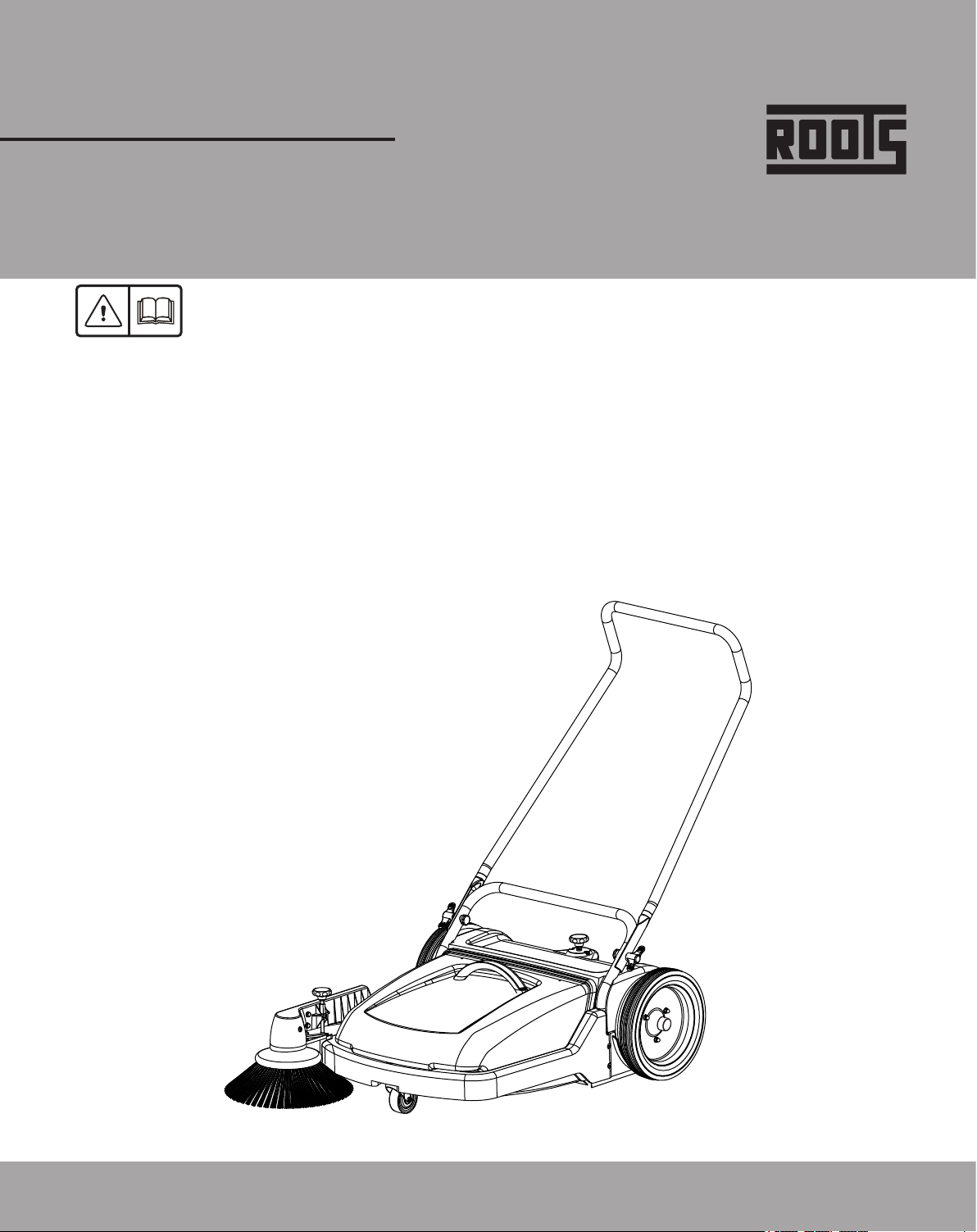
GENERAL SAFETY INSTRUCTION
ŸAbiding by the above general instructions can help
Ÿyou avoid having to read this book while trying to run
Ÿthe machine.
Safety during machine operation
ŸThe machine is applicable for DRY sweeping only.
ŸGround cleaning machines may be run by qualified
personnel only.
ŸThe machine may be used for cleaning such
surfaces approved by the owner or this authorized
representative.
ŸThe operator must use the machine in accordance
to its intended fields of application.
ŸDuring operation, the operator must take account of
local conditions (stairs, obstacles) and of other
persons, particularly children.
Use only genuine spare brooms as specified by
the manufacturer. Use of other than the indicated
broom types may affect safety.
Never collect explosive fluids, undiluted acids
and solvents. This includes e.g. gasoline paint
thinners or fuel oil, which-when combined with
air, may form explosive vapors or mixtures.
Acetone, undiluted acids and solvents can be
aggressive to the material used for the machine
components.
The machine may be used only on indoor
hard floorings and for operation on level
grounds with a maximum inclination of up
to 2 %.
- Do not clean the machine by means of vapour
jet or high pressure cleaning equipment.
- Do not USE the machine on steps.
- Use of the machine in areas prone to explosion
hazards is strictly forbidden.
Transport
ŸIncorrect lifting techniques may create an personal
injury, When transporting the machine ensure that all
components and removable parts are securely
fastened.
ŸDo not lift or transport the machine whilst containing
dirt as this will add considerable weight.
ŸTake extreme care when moving the machine up or
down steps or stairs.
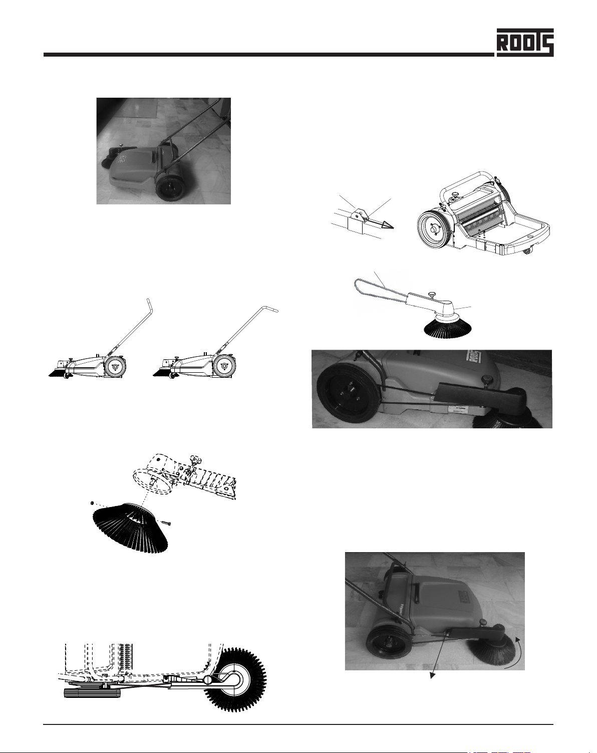
B u m p i n g o v e r
thresholds, kerbs and
similar obstacles can
damage the machine.
Small obstacles can
b e o v e r c o m e b y
pulling the machine
backwards.
Safety & Warning Symbols
All paragraphs in this manual referring to you personal
safety, the safety of your machine and the environment
protection are attributed one of the following warning
symbols.
Symbol
(Hazardous for) Description
Safety Provisions
Caution
Ecological hazard
Read Manual
(persons and goods)
(the machine)
(the environment)
Prior to first operation, read the
manual carefully and strictly
comply with the instructions
contained.
Due to use of substances
re p r e s e n t i n g a n i n he r en t
d a n g e r t o h e a l t h o f
environment.
Im p o r t a n t i n fo r ma ti o n o n
handling the machine in order
to maintain operability.
Safety provisions in dangerous
situation caused by misuse
i n a c c u r a t e a d h e r e n c e o f
i n s t r u ct i o n o r p re s c r i b ed
work routine.
Safety Instructions
ŸApart from information contained in this manual,
generally applicable legal provisions for safety and
prevention of accidents must be adhered to.
ŸDo not put this manual aside without having read it,
even if you have already operated similar ground
cleaning equipment before.
ŸAllow yourself the time to do so in order to save time
at a later time.
ŸThe operator is responsible for all persons in the
working area.
ŸChildren must be kept away from the machine during
operation.
ŸNo person must be allowed to stay in the zone of
danger.
ŸThe warning and instruction plates attached to
machine give important advice on safe operation.
ŸReplace lost or illegible stickers.
ŸBefore starting to work, the operator has to check
that the machine and its working implements are in
proper and safe operating condition.
ŸMachines with known defects must not be used.
ŸIt is important for operators and all persons likely to
use the product, to familiarize themselves with all
accessories and controls, as well as their functions,
before starting operations.
5
+
Flipper

Side Broom Assembly
ŸMount the side broom to the broom plate on the side
arm assembly using Hex Head Bolt and Nylock nut.
Assembly
For ease of packing, the handle and side broom
assembly are packed separately. These parts must be
installed before the machine is put into operation. The
handle is mounted by means of knobs.
Handle can be fixed in two different positions as shown
below.
This machine is exclusively designed for Dry Sweeping
on Solid, Level and Dry surfaces.
Handle position 1 Handle position 2
FIRST OPERATION
ŸPosition the V-Belt from the side arm assembly
Ÿaround the pulley attached to the backside of the
right wheel. In order to do this it will be necessary to
twist the V-Belt. The lower loop of the v-belt should
be coming from the idler pulley (not from the broom
pulley).
ŸCheck for proper rotation and operation of the side
broom. The broom should rotate counter
clockwise(a) when the sweeper is pushed forward-if
not the V-Belt was installed incorrectly. If the belt
slips the tension can be adjusted by loosening the
2 screws(b) that attach the support side broom to
the frame, move the bracket forward, then re-tighten
the screws.
ŸPlace the V-Belt on to the drive pulley on the wheel,
adjust the arm assembly forwards or backwards for
the desired tension. Fasten the arm assembly by
tightening the screws. Check the broom for free
rotation.
FROM IDLER PULLEY
SIDE BROOM ASSY
SUPPORT
SIDE BROOM
MOVE
SCREWS
ŸTo attach the side arm assembly to the main frame
remove the two screws that have already been
inserted into the right side of the main frame.
a
b
6
+
Flipper

MACHINE OPERATION
The machine operates with two brooms. The side broom
takes dirt from the side into the reach of the main broom.
The main broom maintains its direction of rotation to
throw the dirt into the hopper in forward direction of the
machine. To use the machine, simply push it at a normal
walking speed.
MACHINE OPERATION
In case of normal obstacles coming in the way of
sweeping the machine should be pressed down at the
handle. This will cause the two brooms to lift off from the
floor and the machine can easily surmount these
obstacles.
The dirt hopper can be easily lifted by using the handle
provided. The dirt hopper is secured to the machine by
means of the frame. The dirt hopper must be in direct
contact with the broom compartment in order to prevent
leakage of dirt.
The main broom consists of a broom shaft with two
broom core assemblies fastened with six self tapping
screws.
The broom cores can be replaced as below:
ŸUnscrew the self tapping screws.
ŸPull the broom core assembly to the front (broom
viewed from user side) to remove it from the broom
shaft.
Overcoming Obstacles
Emptying of Dirt Hopper
Renewal of Broom Assemblies
When reassembly of the broom ensure the
split pins are fixed in the holes to guide the
broom.
Rubber Sealing Aprons
The rubber aprons avoid leaking of the dust produced
by the broom. Damaged or used aprons cannot fulfil this
task any longer and must be replaced.
ŸUsed for setting of the side broom pressure. The side
broom may touch the floor only by its one third
section, so as to throw the swept matter into the
machine.
1. Pressure Adjustment Knob for Side Broom
2. Pressure adjustment knob for Main Broom
3. Knobs
ŸUsed to secure the handle to the machine or to
reposition it.
-+
Indicates the pressure at which the main
broom has been set. Setting must be
performed as described below :
ŸSet the main broom by turning the knob
clock-wise to increase the pressure, at this
position the scale should read ‘5’ .
ŸStarting with this setting, the main broom
pressure can be increased to meet the
requirement. (As the broom wears out)
4. Main Broom Pressure Reading Scale
ŸTurn the knob in counter-clockwise direction to
reduce the main broom pressure according to the
requirement.
Excess pressure will cause unnecessary
wear of the broom and increased load for the
operator.
Controls
1
3
2
4
ŸThe castor wheel is to keep the pre-
set working height of the side broom.
ŸUsed for setting of the main broom
pressure. The pressure must be set
so as to assure perfect cleaning
operation.
7
+
Flipper

MAINTENANCE
TROUBLE REMEDIAL ACTION
Machine hard to
push/pull
Decrease main broom pressure
setting grease main wheels
Sweeping
unsatisfactory
Increase Main/Side broom
Pressure clean Main/Side
broom check Main broom for
loose bristles
Traces of dirt left
behind the machine Check side/rear rubber aprons.
Side Broom not
rotating Check V- Belt for transmission.
allow it to stay for sometime. The bristles will regain their
correct position gradually.
Maintenance Works
Compliance with our operating and maintenance
instructions will ensure trouble free and smooth
operation of the machine we have supplied.
The machine requires minimum maintenance apart
form the checks by the operator such as Dirt hopper,
Brooms, V-Belt.
Maintenance Intervals
- empty dirt hopper.
- clean the unit.
- check Brooms and Sealing Aprons.
- remove the ropes, tapes etc entangled in the
main broom shaft.
- clean & lubricate.
- trunnion - mainbroom
- grease the main wheels, check the caster
wheel
- check V-belt tension, if necessary, re-tighten.
Daily
Weekly
Monthly
Maintenance Chart
Troubleshooting
Replacement and Tensioning of the V-belt
ŸLift up the side broom arm.
ŸLoosen the clamp screw and pull out the side broom
from the broom arm.
ŸPlace the V-belt through the broom arm and put it on
the V-belt pulley on the broom shaft.
ŸPush the side broom back into the broom arm and re-
tighten the clamp screw.
ŸPlace V-belt into the groove of the right-hand main
wheel.
When the broom arm is lowered down, the V-belt must
be tensioned so as to allow a perfect drive transmission,
if necessary re-tighten by shifting of the side broom arm
bearing.
Greasing of the Main Wheels
For cleaning and greasing of the wheel axle and the gear
ring, the main wheels must be removed as described
below.
ŸRemove hood (a), remove the bolt (b) and domed
cap nut (c) from the wheel (d) and pull the main
wheel.
ŸUnscrew the gear cover and apply grease in the gear
area.
ŸReposition the main wheel.
Replacement of the Side Broom
The side broom can be replaced after removing hex-
bolts from the side broom axle.
Regaining of Bristles
If the bristles have been bent inwards in transit the side
broom must be placed on a flat base, the bristles
pointing outward and a weight must be placed on the
plate. The bristles will regain their correct position
gradually.
If the bristles have been bent outwards, bring them
together apply a rubber band around the bristles and
a
b
c
d
Daily Every
50
Every
100
Every
200
Check Main &
Side Broom
pressure
Check Rubber
Sealing Aprons in
frame & dirt hopper
Maintenance
Works
Operating Hours
MAINTENANCE
Check Gear,
Gearing & Pinion
8
+
Flipper

Do’s
ŸUse the machine in even surface.
ŸClean the dirt hopper each and every time after
every use.
ŸService the machine at the specified intervals
regularly for proper functioning of the machine.
ŸBefore each operation check the main broom, side
broom & dirt hopper of the machine for its proper
function.
ŸRubber sealing aprons must be replaced when it is
damaged or after a long use.
ŸPark the machine in a dry place.
ŸUse only the genuine brooms of Roots or Specified
by the Roots Service Center.
ŸWhen the dirt hopper is full beyond its filling capacity,
empty the dirt hopper.
ŸChildren must be kept away from machine during the
operation.
ŸSide broom to be used only for cleaning corners &
edges.
DO’S & DON’T’S
Don't’s
ŸDo not use the machine in wet slushy and rough
areas.
ŸDo not force the machine to collect heavy debris.
ŸDo not clean the machine with vapour jet or high
pressure cleaning equipment.
ŸDo not let the debris stay in the dirt hopper for a long
period of time.
ŸDo not abuse the machine beyond its operational
tolerance.
ŸDo not use the machine to carry objects.
ŸDo not transport the machine down the stairs by
pushing or pulling.
ŸDo not transport the machine when the dirt hopper is
full.
ŸDo not park the machine in harsh sunlight.
ŸDo not use the machine on steps.
NOTES
9
+
Flipper

SPARE PARTS LIST
10
+
Flipper
FRAME GROUP - Frame, Cover & Plate Assy
9
20
12
11
12 10
14
15
13
18
19
16
17
1
3
7
45
6
8
2
SL. NO PART NO DESCRIPTION QTY
1 553210123-00 FRAME 1
2 553230010-00 GASKET FRAME 1
3 553320088-00 SLEEVE - GROMMET 1
4 553210007-00 WASHER STEEL - 10.5X18.0X4.0 1
5 558320018-00 CASTOR WHEEL ASSY 1
6 552350017-00 WASHER STEEL - 8.4X24X2.0 1
7 552020040-00 HEX HEAD SCREW - M8X45 1
8 552480008-00 HEX NYLOCK NUT - M8 1
9 558210066-00 SIDE PLATE GROUP RH 1
10 558210065-00 SIDE PLATE GROUP LH 1
11 552290005-00 CRPH SELF TAPPING SCREW - 4.8X13 10
12 552350008-00 WASHER STEEL - 5.3X10.0X1.0 18
13 553210124-00 COVER 1
14 552270011-00 CRPH SELF TAPPING SCREW - 6.3X30 4
15 552350011-00 WASHER STEEL - 6.4X12.5X1.6 4
16 553210194-00 BOTTOM COVER THREAD ROD 1
17 552350046-00 WASHER - STEEL - 12.5X24X2.0 1
18 553260042-00 CRPH SELF TAPPING SCREW - 3.5X16 2
19 552350005-00 WASHER STEEL - 4.3X9.0X0.8 2
20 552130011-00 CR PAN HEAD SCREW - STEEL - M5X12 8

FRAME GROUP - Rubber Sealing Strips
11
+
Flipper
1
2
5
6
2
423
SL.NO PART NO DESCRIPTION QTY
1 553210163-00 SPLASH SHIELD 1
2 553210109-00 SELF TAPPING SCREW W/COLLAR - 4.8X13 19
3 553210224-00 SIDE RUBBER STRIP 2
4 553210226-00 SIDE STRIP HOLDER 2
5 553210225-00 REAR RUBBER STRIP 1
6 553210227-00 REAR STRIP HOLDER 1

FRAME GROUP - Brush Shaft Assy
12
+
Flipper
1
11 17
16
5
6
3
15
7
8
4
16
12
2
10
18
13
14
9
SL.NO PART NO DESCRIPTION QTY
1 558210062-00 BRUSH SHAFT GROUP 1
2 558210064-00 PRESSURE ADJUSTMENT GROUP 1
3 553210189-00 BOOT 2
4 553210190-00 SEAL 2
5 552320007-00 CRCSK SELF TAPPING SCREW- STEEL - 3.5X12.7 4
6 553210167-00 SPLIT PIN – 63 2
7 553210152-00 TRUNNION SHAFT 1
8 553210202-00 SPACER THREAD ROD 1
9 558210060-00 THREAD ROD ASSY 1
10 553210195-00 TOP COVER THREAD ROD 1
11 552130013-00 CR PAN HEAD SCREW STEEL - M5X20 2
12 553260042-00 CRPH SELF TAPPING SCREW - 3.5X16 2
13 552250004-00 HEX LOCK NUT STEEL - M8 2
14 558210109-00 TOP KNOB ASSY 1
15 553210199-00 INDICATOR 1
16 552350005-00 WASHER STEEL - 4.3X9.0X0.8 3
17 552280010-00 CRPH SELF TAP SCREW - 3.5X25 1
18 558210067-00 THREAD ROD GROUP 1

FRAME GROUP - Gear Assy
1
2
3
4
5
6
7
8
19
10
12
13
16
17
18
11
14
15
9
13
+
Flipper
SL NO PART NO DESCRIPTION QTY
1 553210178-00 WHEEL CAP 2
2 552230024-00 HEX SOC HEAD CAP SCREW -STEEL - M8X20 2
3 552350017-00 WASHER-STEEL-8.4X24X2 2
4 552300002-00 DOMED CAP NUT-SS 304 - M6 6
5 552350011-00 WASHER-STEEL - 6.4X12.5X1.6 6
6 558210053-00 TYRE ASSY 2
7 553210191-00 PROTECTION DISK 2
8 553260042-00 CRPH SELF TAPPING SCREW - 3.5X16 6
9 553210192-00 GEAR COVER BOTTOM 2
10 558210071-00 GEAR ASSY 2
11 553210188-00 WASHER STEEL - 20X28X0.5 2
12 553230016-00 CIRCLIP EXTERNAL - A 16 2
13 553210064-00 WASHER – STEEL - 16X22X0.5 2
14 553210006-00 KEY 2
15 553210157-00 PINION 2
16 553210063-00 WASHER – STEEL - 16X22X1.5 2
17 553230014-00 CIRCLIP EXTERNAL - A 17 2
18 552610011-00 DG BALL BEARING 6003 2 RS 2
19 553210193-00 GEAR COVER 2

FRAME GROUP - Handle Assy
1
2
3
4
5
6
7
14
+
Flipper
SLNO PART NO DESCRIPTION QTY
1 553210166-00 HANDLE 1
2 552210018-00 HEX SOC CSK HEAD SCREW- STEEL - M6X45 4
3 552350011-00 WASHER STEEL - 6.4X12.5X1.6 4
4 552480007-00 HEX NYLOCK NUT-STEEL GR.8 -M6 4
5 553210168-00 UPPER HANDLE 1
6 553210173-00 KNOB ASSY MALE 2
7 558320139-00 KNOB-HANDLE 2

FRAME GROUP - Main Broom Assy
15
+
Flipper
SL. NO PART NO DESCRIPTION QTY
1 558210057-00 MAIN BRUSH 1
2 552270010-00 CRPH SELF TAPPING SCREW-STEEL - 4.8X40 6
1
2

HOPPER GROUP - Hopper Assy
16
+
Flipper
7
4
56
23
8
9
10
11
1
SL. NO PART NO DESCRIPTION QTY
1 558210082-00 HOPPER ASSEMBLY 1
2 553210171-00 HANDLE FLIPPER 1
3 552020007-00 HEX HEAD SCREW - M6X16 2
4 553210228-00 BOOT FRONT 2
5 552350011-00 WASHER STEEL - 6.4X12.5X1.6 2
6 552480007-00 HEX NYLOCK NUT - M6 2
7 553210208-00 GASKET HOPPER 1
8 558210079-00 HOPPER FLAP ASSY - IH 1
9 552130011-00 CR PAN HEAD SCREW - M5X12 6
10 552350030-00 WASHER STEEL - 5.3X13X1.0 6
11 553210174-00 HOPPER RUBBER APRON 1

SIDE BROOM GROUP - Side Broom Assy Complete
1
24
3
5
8
9
6
7
10
11
14
12
15
12
13
17
+
Flipper
SL. NO PART NO DESCRIPTION QTY
1 553210130-00 MOLDED SIDE ARM 1
2 553210101-00 TAPER BUSH SIDE BROOM ARM 1
3 553210017-00 SUPPORT SIDE BROOM ARM 1
4 553210013-00 CLEVIS PIN SIDE BROOM ARM 1
5 553230013-00 CIRCLIP EXTERNAL - A 12 1
6 558210028-00 SIDE BROOM ASSY COMPLETE 1
7 553210099-00 V-BELT 1
8 558210019-00 IDLER BRACKET ASSY 1
9 553210111-00 HEX HEAD SCREW – M6x16/13 mm COLLAR 2
10 553210210-00 CRPH STS – 6.3X30 MACHINED 1
11 558210012-00 KNOB ASSY 1
12 552170012-00 HEX NUT STEEL - M8 2
13 553210018-00 NUT SIDE BROOM KNOB 1
14 553210011-00 THREADED ROD – SIDE BROOM 1
15 553210012-00 PROTECTION CAP THREAD ROD 1

28
29
32
SIDE BROOM GROUP - Side Broom Assy Complete
18
+
Flipper
16
18
17
18
20
22
25
21
26
24
27
30
31
23
19
SL. NO PART NO DESCRIPTION QTY
16 553230015-00 EXTERNAL CIRCLIP - A 10 1
17 553210015-00 BEARING HOUSING – SIDE BROOM ARM 1
18 552610002-00 BEARING – 6000 ZZ 2
19 553210007-00 WASHER STEEL - 10.5X18X4 1
20 553210116-00 AXLE – SIDE BROOM 1
21 553210064-00 WASHER STEEL - 16.2X22X0.5 2
22 553210014-00 V-BELT PULLEY 1
23 553210006-00 KEY 1
24 553230008-00 WASHER STEEL - 14.2X20X0.5 1
25 553230016-00 EXTERNAL CIRCLIP - A 16 1
26 553230006-00 DEFLECTOR ROLLER 1
27 558230001-00 SIDE BROOM 1
28 552270011-00 CRPH SELF TAP SCREW – STEEL - 6.3X30 2
29 552350011-00 WASHER-STEEL - 6.4X12.5X1.6 2
30 552020010-00 HEX HEAD SCREW - STEEL 8.8 - M6X30 1
31 552480006-00 HEX NYLOCK NUT-STEEL GR.6 - M6 3
32 558210056-00 SIDE BROOM GROUP 1


Roots Multiclean Ltd.
R.K.G. Industrial Estate, Ganapathy,
Coimbatore - 641 006, India.
Phone: +91 (422) 4330 330
E-mail: [email protected]
Web: rootsmulticlean.in
Toll Free: 1800 425 1330
Table of contents
Other ROOTS Blower manuals
Popular Blower manuals by other brands

Hyundai power products
Hyundai power products HAS30TCL Original instructions

SAINT-GOBAIN
SAINT-GOBAIN CertainTeed Volu-Matic 500 Operation Manual and Safety Information

Meec tools
Meec tools 721-332 User instructions

Ryobi
Ryobi RBV2400CSV Original instructions

Schiller
Schiller Steiner 75-70644A parts manual

Gude
Gude GKM 700 Translation of the original instructions