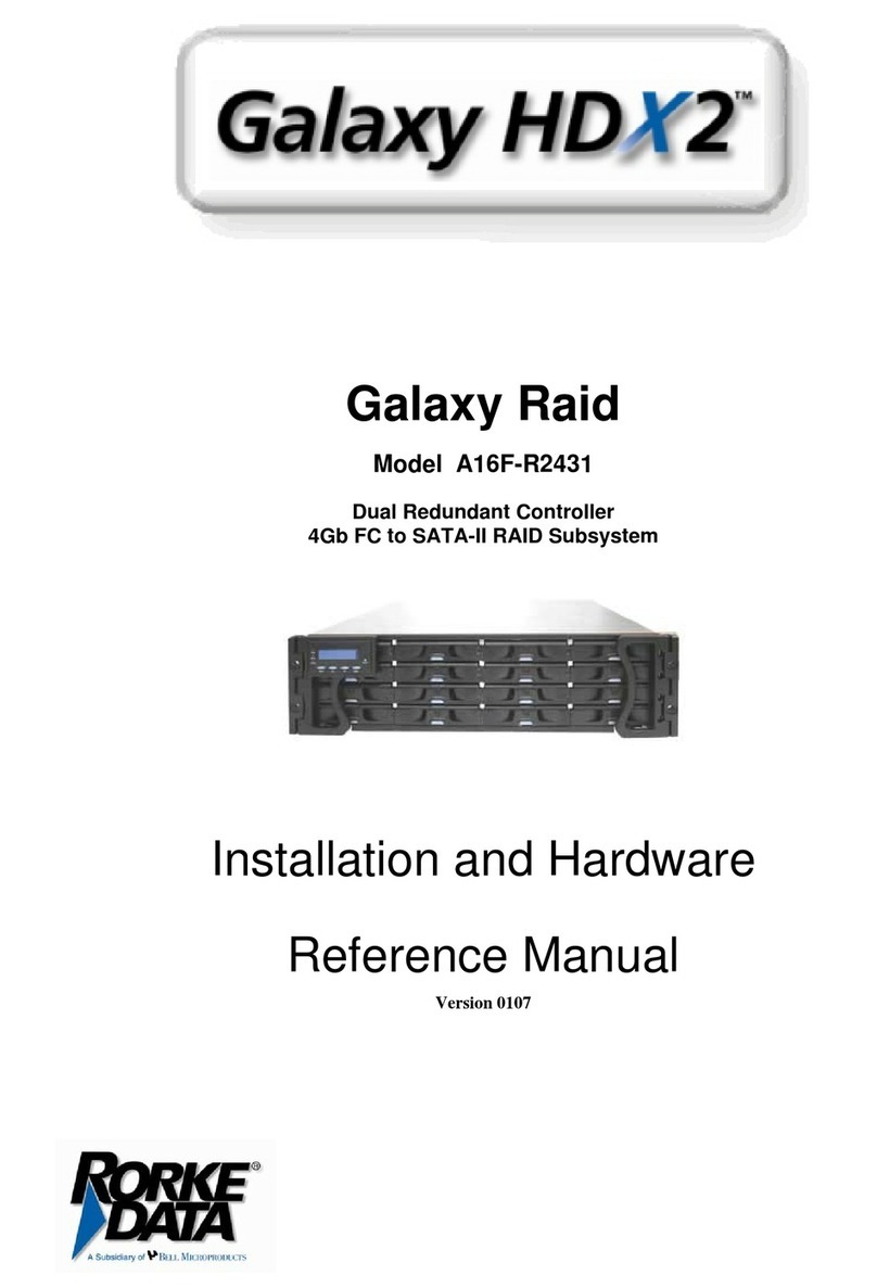
Rorke Data Galaxy HDX2-2430S-16U4D User manual

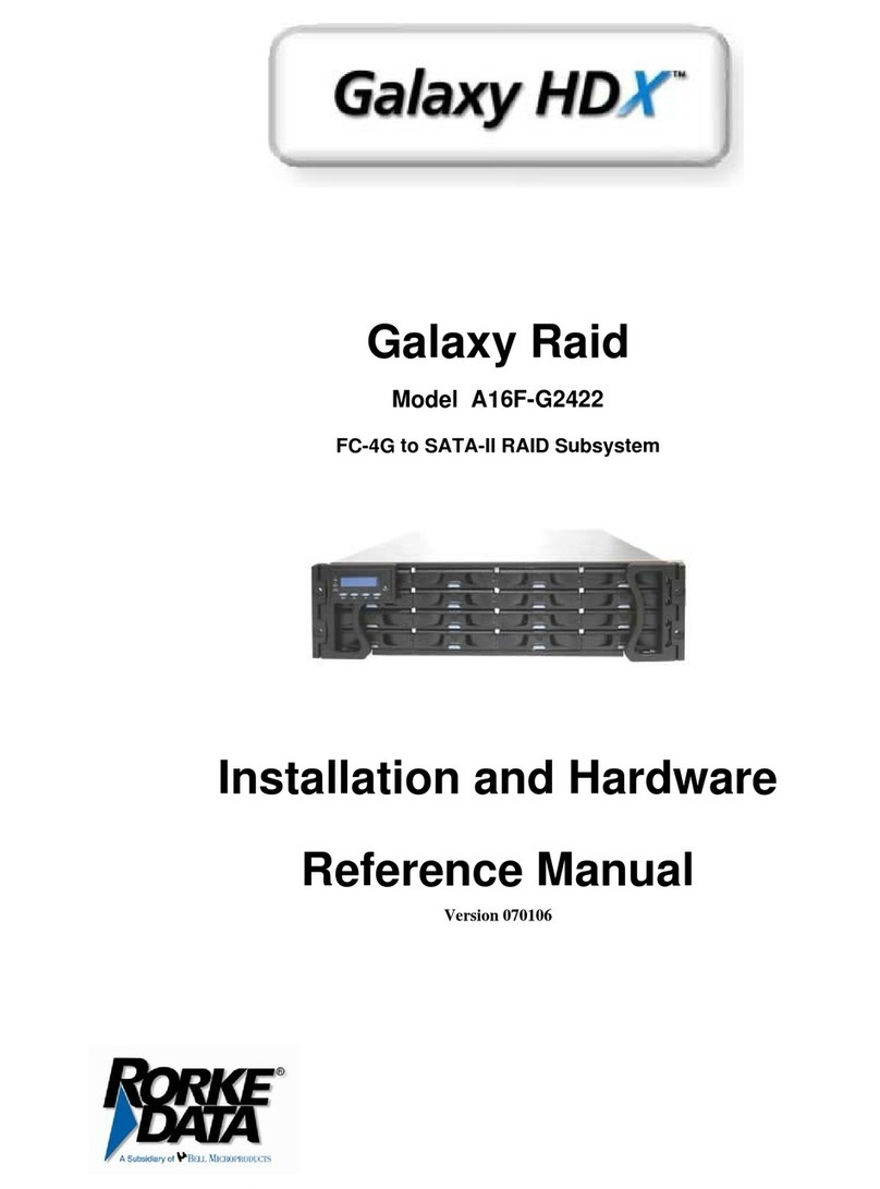
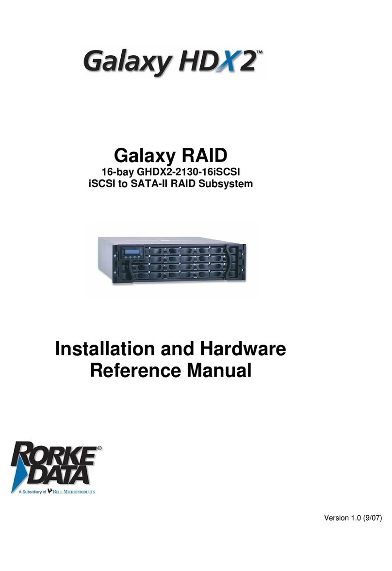
Galaxy Raid
Model GHDX2-2430S-16U4D
16 Bay U320 SCSI to SATA-II RAID Subsystem
Installation and Hardware
Reference Manual
Version 060107
Version 1.0 (08, 2005)

Galaxy Raid Installation and Hardware Reference Manual
ii
Contact Information
Americas
Rorke Data Inc
7626 Golden Triangle Drive
Eden Prairie, MN 55344
USA
Tel: +1-800 328 8147
Fax: +1-952 829 0988
http://www.rorke.com

Galaxy Raid GHDX2-2430S-16U4D Raid Installation and Hardware Reference Manual
iii
Copyright 2006
This Edition First Published 2006
All rights reserved. This publication may not be reproduced, transmitted,
transcribed, stored in a retrieval system, or translated into any language or
computer language, in any form or by any means, electronic, mechanical,
magnetic, optical, chemical, manual or otherwise, without the prior written
consent of Rorke Data , Inc.
Disclaimer
Rorke Data makes no representations or warranties with respect to the
contents hereof and specifically disclaims any implied warranties of
merchantability or fitness for any particular purpose. Furthermore, Rorke
Data reserves the right to revise this publication and to make changes from
time to time in the content hereof without obligation to notify any person of
such revisions or changes. Product specifications are also subject to change
without prior notice.
Trademarks
Galaxy and the Galaxy logo are registered trademarks of Rorke Data , Inc.
PowerPC®is a trademark of International Business Machines Corporation
and Motorola Inc.
Solaris and Java are trademarks of Sun Microsystems, Inc.
All other names, brands, products or services are trademarks or registered
trademarks of their respective owners.

Galaxy Raid Installation and Hardware Reference Manual
iv
Warnings and Certifications
Restricted Access Location:
This equipment is intended to be installed in a RESTRICTED ACCESS LOCATION only.
Electric Shock Warning!
To Prevent Electric Shock:
Access to this equipment is granted only to trained operators and service personnel who have
been instructed of and fully understand the possible hazardous conditions and the
consequences of accessing non-field-serviceable units. For example, accessing the backplane
may cause electric shock.
FCC (applies in the U.S. and Canada)
FCC Class A Note
This device complies with Part 15 of the FCC rules. Operation is subject to
the following two conditions: (1) this device may not cause harmful
interference, and (2) this device may accept any interference received,
including interference that may cause undesired operation.
NOTE:
This equipment has been tested and found to comply with the limits for a
Class A digital device, pursuant to Part 15 of the FCC Rules. These limits
are designed to provide reasonable protection against harmful interference
when the equipment is operated in a commercial environment. This
equipment generates, uses, and can radiate radio frequency energy and, if
not installed and used in accordance with the instruction manual, may cause
harmful interference to radio communications. Operation of this equipment
in a residential area is likely to cause harmful interference in which case the
user will be required to correct the interference at his own expense.
The changes or modifications not expressly approved by the party
responsible for compliance could void the user’s authority to operate the
equipment.
WARNING:
Use only shielded cables to connect I/O devices to this equipment.

Galaxy Raid GHDX2-2430S-16U4D Raid Installation and Hardware Reference Manual
v
You are cautioned that changes or modifications not expressly approved by
the party responsible for compliance could void your authority to operate the
equipment.
CB
This device meets the requirements of the CB standard for electrical
equipment with regard to establishing a satisfactory level of safety for
persons using the device and for the area surrounding the apparatus.
This standard covers only safety aspects of the above apparatus; it
does not cover other matters, such as style or performance.
CCC for Power Supplies’ compatibility to China Compulsory Certification.
This device is in conformity with UL standards for safety.
ITE BSMI Class A, CNS 13438 (for Taiwan)
This device is in conformity with UL standards for safety.
RoHS 2002/96/EC compliant
WEEE Disposal of Old Electrical and Electronic Equipment
This device is in conformity with the EMC.
This device is in conformit
y
with the CB safet
y
specifications.

Galaxy Raid Installation and Hardware Reference Manual
vi
Table of Contents
Table of Contents
CHAPTER 1 INTRODUCTION
1.1 PRODUCT OVERVIEW .......................................................................................1-1
1.1.1 Product Introduction............................................................................................. 1-1
1.2 CHASSIS OVERVIEW..........................................................................................1-2
1.2.1 Front Panel Overview ........................................................................................... 1-2
1.2.2 Rear Panel Overview............................................................................................. 1-3
1.2.3 Back-plane Board.................................................................................................. 1-4
1.2.4 Physical Dimensions ............................................................................................. 1-4
1.3 SUBSYSTEM COMPONENTS............................................................................1-4
1.3.1 LCD Keypad Panel................................................................................................ 1-5
1.3.2 Drive Trays............................................................................................................ 1-5
1.3.3 The RAID Controller Module................................................................................ 1-6
1.3.4 Controller Module Interfaces................................................................................ 1-7
1.3.5 DIMM Module....................................................................................................... 1-8
1.3.6 BBU.......................................................................................................................1-9
1.3.7 Power Supply Units............................................................................................. 1-10
1.3.8 Cooling Modules ................................................................................................. 1-11
1.4 SUBSYSTEM MONITORING............................................................................1-12
1.4.1 I2C bus ................................................................................................................ 1-12
1.4.2 LED Indicators.................................................................................................... 1-12
1.4.3 Firmware (FW) and RAIDWatch GUI ................................................................ 1-13
1.4.4 Audible Alarms.................................................................................................... 1-13
1.5 HOT-SWAPPABLE COMPONENTS.................................................................1-13
1.5.1 Hot-swap Capabilities......................................................................................... 1-14
1.5.2 Components......................................................................................................... 1-14
CHAPTER 2 HARDWARE INSTALLATION
2.1 INTRODUCTION..................................................................................................2-1
2.2 INSTALLATION PREREQUISITES....................................................................2-1
2.3 SAFETY PRECAUTIONS.....................................................................................2-2
2.3.1 Precautions and Instructions................................................................................. 2-2
2.3.2 Static-free Installation........................................................................................... 2-4
2.4 GENERAL INSTALLATION PROCEDURE.......................................................2-5
2.4.1 Installation Procedure Flowchart......................................................................... 2-6
2.5 UNPACKING THE SUBSYSTEM........................................................................2-6
2.5.1 Pre-installed Components ..................................................................................... 2-7
2.5.2 Uninstalled Components ....................................................................................... 2-7
2.6 HARD DRIVE INSTALLATION..........................................................................2-7
2.6.1 Hard Drive Installation Prerequisites................................................................... 2-7
2.6.2 Drive Installation .................................................................................................. 2-8
2.7 DRIVE TRAY INSTALLATION ..........................................................................2-9
2.8 BBU INSTALLATION........................................................................................2-10
2.8.1 BBU Module Installation Overview .................................................................... 2-10
2.8.2 BBU Warnings and Precautions.......................................................................... 2-11
2.8.3 Installation Procedure......................................................................................... 2-12
2.9 RACK/CABINET INSTALLATION...................................................................2-14

Galaxy Raid GHDX2-2430S-16U4D Raid Installation and Hardware Reference Manual
vii
CHAPTER 3 SUBSYSTEM CONNECTION
3.1 SCSI CONNECTION OVERVIEW.......................................................................3-1
3.1.1 SCSI Cables........................................................................................................... 3-1
3.1.2 SCSI Port on the Controller Rear Panel ............................................................... 3-1
3.1.3 SCSI Termination.................................................................................................. 3-2
3.2 HOST CONNECTION SAMPLE TOPOLOGIES.................................................3-2
3.2.1 Basic Configuration Rules..................................................................................... 3-2
3.2.2 Simple, Direct Connection to Single Host Computer............................................ 3-3
3.2.3 Dual Path Redundant Connection......................................................................... 3-4
3.3 DAISY CHAIN ......................................................................................................3-5
3.3.1 Daisy Chain Topology........................................................................................... 3-5
3.3.2 Daisy Chain Procedures........................................................................................ 3-7
CHAPTER 4 SUBSYSTEM OPERATION AND MONITORING
4.1 POWER ON ...........................................................................................................4-1
4.1.1 Check List.............................................................................................................. 4-1
4.1.2 Power On Procedure............................................................................................. 4-1
4.1.3 Power On Status Check......................................................................................... 4-2
4.1.4 LCD Screen ........................................................................................................... 4-3
4.2 POWER OFF PROCEDURE .................................................................................4-4
4.3 SUBSYSTEM MONITORING OVERVIEW........................................................4-5
4.4 STATUS INDICATING LEDS..............................................................................4-6
4.4.1 Brief Overview of the LEDs................................................................................... 4-6
4.4.2 LCD Keypad Panel................................................................................................ 4-7
4.4.3 Drive Tray LEDs................................................................................................... 4-8
4.4.4 Controller Module LEDs....................................................................................... 4-9
4.4.5 LAN Port LEDs ................................................................................................... 4-10
4.4.6 BBU Module LED ............................................................................................... 4-10
4.4.7 PSU LEDs ........................................................................................................... 4-12
4.4.8 Cooling Module LEDs......................................................................................... 4-12
4.5 AUDIBLE ALARM.............................................................................................4-13
4.5.1 Default Threshold Values.................................................................................... 4-14
4.5.2 Failed Devices..................................................................................................... 4-14
4.6 I2C MONITORING .............................................................................................4-15
CHAPTER 5SUBSYSTEM MAINTENANCE
5.1 OVERVIEW...........................................................................................................5-1
5.1.1 About Subsystem Maintenance.............................................................................. 5-1
5.1.2 General Notes on Component Replacement.......................................................... 5-1
5.2 REPLACING CONTROLLER MODULE COMPONENTS.................................5-2
5.2.1 Controller Module Maintenance Overview........................................................... 5-2
5.2.2 Removing the Controller Module.......................................................................... 5-3
5.2.3 Replacing the Controller Module.......................................................................... 5-4
5.3 DIMM MODULE REPLACEMENT.....................................................................5-6
5.3.1 DIMM Module Considerations.............................................................................. 5-6
5.3.2 DIMM Module Replacement ................................................................................. 5-7
5.4 REPLACING AFAULTY BBU ............................................................................5-8
5.4.1 BBU Warnings and Precautions............................................................................ 5-9
5.4.2 Replacing a BBU................................................................................................. 5-10
5.5 REPLACING AFAULTY PSU MODULE..........................................................5-11
5.5.1 PSU Module Overview........................................................................................ 5-11
5.5.2 Replacing the PSU Module ................................................................................. 5-12
5.6 COOLING MODULE MAINTENANCE ............................................................5-14
5.6.1 Cooling Module Overview................................................................................... 5-14
5.6.2 Replacing a Cooling Module............................................................................... 5-15
5.7 REPLACING AFAILED HARD DRIVE............................................................5-16
5.7.1 Hard Drive Maintenance Overview .................................................................... 5-16
Galaxy Raid Installation and Hardware Reference Manual
viii
5.7.2 Replacing a Hard Drive ...................................................................................... 5-17
APPENDIX ASPECIFICATIONS
A.1 TECHNICAL SPECIFICATIONS........................................................................A-1
A.2 FUNCTIONAL SPECIFICATIONS.....................................................................A-3
A.3 DRIVE TRAY SPECIFICATIONS.......................................................................A-3
A.4 POWER SUPPLY SPECIFICATIONS.................................................................A-4
A.5 COOLING MODULE SPECIFICATIONS...........................................................A-4
A.6 RAID MANAGEMENT........................................................................................A-5
A.7 FAULT TOLERANCE MANAGEMENT............................................................ A-5
APPENDIX BSPARE PARTS AND ACCESSORIES
B.1 SPARE PARTS ..................................................................................................... B-1
B.2 ACCESSORIES .................................................................................................... B-2
APPENDIX C PIN OUTS
C.1 VHDCI SCSI PORT PINOUTS............................................................................. C-1
C.2 DB9 AUDIO JACK PINOUTS ............................................................................. C-2
C.2.1 COM1 Serial Port Cable ......................................................................................C-2
C.2.2 COM2 Serial Port Cable to UPS..........................................................................C-3
C.3 NULL MODEM.................................................................................................... C-4
C.4 ETHERNET PORT PINOUTS.............................................................................. C-5
C.5 MAIN POWER...................................................................................................... C-5
APPENDIX D UNINTERRUPTIBLE POWER SUPPLY
D.1 UNINTERRUPTIBLE POWER SUPPLY OVERVIEW......................................D-1
D.2 COMPATIBLE UPS SUPPLIES...........................................................................D-1
D.3 SERIAL COMMUNICATION CABLE................................................................D-1
D.4 CONNECTING THE UPS TO THE SUBSYSTEM..............................................D-2
D.4.1 Connect the PSU Module Power Cords ...............................................................D-2
D.4.2 Set the Baud Rate..................................................................................................D-2
D.4.3 Connect COM2.....................................................................................................D-2
D.5 POWER ON ..........................................................................................................D-3
D.6 UPS STATUS MONITORING .............................................................................D-3
D.6.1 Normal Operational Status...................................................................................D-3
D.6.2 UPS Messages......................................................................................................D-4
D.6.3 UPS Message Summary........................................................................................D-5

Galaxy Raid GHDX2-2430S-16U4D Raid Installation and Hardware Reference Manual
ix
Safety Precautions
Precautions and Instructions
•Prior to powering on the subsystem, ensure that the correct power range is being
used.
•The GALAXY subsystem comes with sixteen (16) drive bays. Leaving any of
these drive bays empty will greatly affect the efficiency of the airflow within the
enclosure, and will consequently lead to the system overheating, which can
cause irreparable damage.
•If a module fails, leave it in place until you have a replacement unit and you are
ready to replace it.
•Airflow Consideration: The subsystem requires an airflow clearance, especially
at the front and rear.
•Handle subsystem modules using the retention screws, eject levers, and the metal
frames/face plates. Avoid touching PCB boards and connector pins.
•To comply with safety, emission, or thermal requirements, none of the covers or
replaceable modules should be removed. Make sure that during operation, all
enclosure modules and covers are securely in place.
•Be sure that the rack cabinet into which the subsystem chassis will be installed
provides sufficient ventilation channels and airflow circulation around the
subsystem.
•Provide a soft, clean surface to place your subsystem on before working on it.
Servicing on a rough surface may damage the exterior of the chassis.
•If it is necessary to transport the subsystem, repackage all disk drives separately.
•Dual redundant controller models come with two controller modules that must
be installed into the subsystem. Single controller modules come with a single
controller module and a metal sheet is placed over the lower controller bay at the
rear of the subsystem. Since single controller modules cannot be upgraded, this
metal sheet should NEVER be removed.
ESD Precautions
Observe all conventional anti-ESD methods while handling system
modules. The use of a grounded wrist strap and an anti-static work pad are
recommended. Avoid dust and debris in your work area.

Galaxy Raid Installation and Hardware Reference Manual
x
About This Manual
This manual:
•Introduces the GALAXY RAID subsystem series.
•Describes all the active components in the subsystem.
•Provides recommendations and details about the hardware installation
process.
•Briefly describes how to monitor the subsystem.
•Describes how to maintain the subsystem.
This manual does not:
•Describe components that are not user-serviceable.
•Describe the configuration options of firmware, using terminal
emulation programs, or the RAIDWatch GUI software that came with
your subsystem.
•Give a detailed description of the RAID controllers embedded within
the subsystem.
Revision History
♦Initial release
Who should read this manual?
This manual assumes that its readers are experienced with computer
hardware installation and are familiar with storage enclosures.
Related Documentation
•User’s Operation Manual
•RAIDWatch User’s Manual
These two documents can be found in the product utility CD included with
your subsystem package.

Galaxy Raid GHDX2-2430S-16U4D Raid Installation and Hardware Reference Manual
xi
Conventions
Naming
From this point on and throughout the rest of this manual, the GALAXY
series is referred to as simply the “subsystem” or the “system” and
GALAXY is frequently abbreviated as “GAL.”
Lists
Bulleted Lists: Bulleted lists are statements of non-sequential facts. They
can be read in any order. Each statement is preceded by a round black dot
“•.”
Numbered Lists: Numbered lists are used to describe sequential steps you
should follow in order.
Important information that users should be aware of is indicated with the
following icons:
NOTE:
These messages inform the reader of essential but non-critical
information. These messages should be read carefully as any directions
or instructions contained therein can help you avoid making mistakes.
CAUTION!
Cautionary messages should also be heeded to help you reduce the
chance of losing data or damaging the system.
IMPORTANT!
The Important messages pertain to use the GALAXY subsystem
introduced in this manual.
WARNING!
Warnings appear where overlooked details may cause damage to the
equipment or result in personal injury. Warnings should be taken
seriously.

Galaxy Raid Installation and Hardware Reference Manual
xii
Software and Firmware Updates
latest software or firmware updates.
Problems that occur during the updating process may cause unrecoverable
errors and system down time. Always consult technical personnel before
proceeding with any firmware upgrade.
NOTE:
The firmware version installed on your system should provide the
complete functionality listed in the specification sheet/user’s manual.
We provide special revisions for various application purposes.
Therefore, DO NOT upgrade your firmware unless you fully understand
what a firmware revision will do.

Chapter 1: Introduction
Product Overview 1-1
Chapter 1
Introduction
1.1 Product Overview
1.1.1 Product Introduction
This hardware manual briefly introduces the Galaxy GHDX2-2430S-16U4D
SCSI-320 to SATA-II storage subsystem shown in Figure 1-1. The
GALAXY subsystem comes with two (2) 320MB/second SCSI (SCSI-320)
host channels. This high-density subsystem supports up to sixteen (16)
SATA-II hard drives in a 3U profile chassis. The subsystem is managed by a
RAID controller module
powered by the ASIC400 XOR
engine featuring the latest
RAID6 technologies. The
subsystem comes with a pre-
installed 256MB DDR RAM
DIMM module that can be
replaced by one with the 2GB capacity. The SCSI-320 host channels feature
packet protocols with reduced command overhead and provide increased
transfer speed and abundant bandwidth.
The subsystem is equipped with a dedicated hardware XOR for RAID6
acceleration. A RAID6 array configuration allows two (2) disk drive failures
to occur at the same time. This feature marks a giant step forward for
providing a higher level of data integrity. RAID level 6 and the
combinations of striped RAID6 arrays (RAID60) are both supported.
Two (2) dual-stacked VHDCI SCSI connectors connect the subsystem to
host computers and/or cascaded subsystems. Two (2) redundant cooling
modules provide cooling airflow within the subsystem. Two (2) redundant
and hot-swappable power supply unit (PSU) modules provide constant
power to the subsystem. A battery backup unit (BBU) is accessible and hot-
swappable through the rear panel. The modular design of the subsystem
provides the ease of access to all major modules and hence reduces the
maintenance efforts.
NOTE:
On receiving and unpacking your subsystem, please check the package
contents against the included Unpacking List. If any modules appear to be
damaged or missing, please contact your subsystem vendor immediately.
Figure 1-1: GHDX2-2430S-16U4D Subsystem

Galaxy Raid GHDX2-2430S-16U4D Installation and Hardware Reference Manual
1-2 Chassis Overview
1.2 Chassis Overview
The GALAXY RAID storage subsystem comes in a robust 3U-profile metal
chassis. The chassis is comprised of the front and rear sections, which are
respectively accessed through the front and rear panels. We provide
separately purchased mounting rails or end-brackets for the installation into
a standard 19” rack cabinet. Detailed description of major components can
be found in the following sections.
NOTE:
Components accessed through the front panel are referred to as “Front
Panel Components” and components accessed through the rear panel are
referred to as “Rear Panel Components.”
1.2.1 Front Panel Overview
The front section of the subsystem features a 4 x 4 layout for sixteen (16)
3.5-inch hard disk drives. The subsystem comes with an LCD keypad
panel. If your subsystem comes an LCD keypad, two (2) handles will be
available on the front of the subsystem. The front handles enable you to
easily insert/extract the chassis into/from a rack or cabinet. The LCD keypad
panel provides an easy access to the subsystem’s self-monitoring and RAID
configuration utilities.
The front panel of the GALAXY RAID subsystem is shown in Figure 1-2.
Figure 1-2: GALAXY Front View – the LCD Version
The front panel shown in Figure 1-2 accommodates the following
components:
•Drive bays with drive tray canisters: The subsystem has sixteen
(16) drive bays accessible through the front side of the chassis.
•Right handle and left handle with an LCD keypad panel: These
front handles are conveniently placed and simplify moving the
subsystem enclosure into and out of a rack cabinet. The left side
front-handle combines a 16x2 character LCD keypad that can be

Chapter 1: Introduction
Chassis Overview 1-3
used for subsystem configuration, troubleshooting and status
monitoring. (Please refer to Section 1.3.1)
1.2.2 Rear Panel Overview
The rear section of the GALAXY subsystem is accessed through the rear
panel and is reserved for a single RAID controller module, one (1) optional
BBU, two (2) power supply units (PSUs) and two (2) cooling modules.
The rear panel of the RAID subsystem is shown in Figure 1-3. The
descriptions of rear panel components are given below:
Figure 1-3: GALAXY Rear View
The rear panel shown in Figure 1-3 accommodates the following
components:
•RAID controller module:A RAID controller module is installed in
the GALAXY. The controller module contains a RAID controller
board, a module bay for the optional battery module, and a DDR
RAM DIMM module. (See Section 1.3.3)
•BBU: An optional BBU sustains cache memory during a power
shortage to prevent data loss. (See Section 1.3.6)
•PSUs: The hot-swappable PSUs provide power to the subsystem.
The subsystem is powered on or off using the power switches on
the PSUs. (See Section 1.3.7)
•Cooling modules: The redundant cooling modules ventilate the
subsystem. (See Section 1.3.8)
•Dummy plate: The GALAXY is a single controller subsystem. The
RAID controller module is installed in the upper controller bay. A
dummy plate covers the lower controller bay at the rear of the
subsystem.

Galaxy Raid GHDX2-2430S-16U4D Installation and Hardware Reference Manual
1-4 Subsystem Components
1.2.3 Backplane Board
An integrated backplane board separates the front and rear sections of the
chassis. This backplane provides logic level signals and low voltage power
paths. The backplane also comes with thermal sensors and I2C devices to
detect system temperature and the operating status of the PSU/cooling
modules. This board contains no user-serviceable components.
1.2.4 Physical Dimensions
The GALAXY comes in an enhanced 3U chassis with the following
dimensions:
•With handles: 482.6mm (W) x 131mm (H) x 504.3mm (L) (19 x
5.2 x 19.8 inches)
•Without handles: 445mm (W) x 130mm (H) x 488.2mm (L) (17.5 x
5.1 x 19.2 inches)
1.3 Subsystem Components
The subsystem houses many active components and most of them can be
accessed through either the front or rear panel. The modular design of the
active components facilitates installation and removal of these components.
Hot-swap mechanisms are incorporated to eliminate power surges and signal
glitches that might occur while removing or installing these modules. Each
component is further described below:
1.3.1 LCD Keypad Panel
Figure 1-4: LCD Keypad Panel
PN: GAL-9273CHandLLCD
The LCD keypad panel shown in Figure 1-4 consists of a 2-rows x 16-
characters LCD screen with push buttons and LED status indicators. The
LCD front panel provides full access to all RAID configuration settings and
monitoring functions. After powering up the subsystem, the initial screen

Chapter 1: Introduction
Subsystem Components 1-5
will show the subsystem model name. A different name may be assigned for
the subsystem or different RAID arrays. This enables easier identification in
a topology with numerous arrays.
1.3.2 Drive Trays
Figure 1-5: Drive Tray Front View
PN: GAL-9273CDTray
The GALAXY subsystem comes with sixteen (16) drive trays (See Figure
1-5) designed to accommodate separately purchased standard 1-inch pitch,
3.5-inch disk drives. The drive bays are accessible from the front of the
enclosure. Two (2) LEDs on the front of the tray indicate drive operating
statuses. A key-lock on each drive tray secures the hard drive in place, while
a release button can be used to release the locking mechanism should the
need arises for retrieving a disk drive.
WARNING!
Be careful not to warp, twist, or contort the drive tray in any way (e.g., by
dropping it or resting heavy objects on it). The drive tray has been
customized to fit into the drive bays in the subsystem. If the drive bay
structure is deformed or altered, the drive trays may not fit into the drive
bays.
The subsystems are housed in an enclosure that is 4 bays wide and 4 bays
high. Drive bay are numbered from Slot 1 to Slot 16 from left to right, and
then from top to bottom.
Figure 1-6: Drive Bay Numbering Sequence

Galaxy Raid GHDX2-2430S-16U4D Installation and Hardware Reference Manual
1-6 Subsystem Components
1.3.3 The RAID Controller Module
Figure 1-7: RAID Controller Module
PN: GAL-83AU24GE16 (without DDR RAM)
The RAID controller module that came with your subsystem contains a
controller board, a BBU adapter board, a rear-facing faceplate, and a pre-
installed DDR RAM DIMM module. The BBU adapter board is pre-
installed in the controller module and is not user-serviceable. The DDR
RAM DIMM socket is strategically placed on an easily accessible location
on the controller board. (See Figure 1-7) A BBU slot on the top center of
the controller module is reserved for a hot-replaceable BBU module.
The controller module contains no user-serviceable components. Except
when installing/upgrading the cache memory inside, the controller module
should never be removed or opened.
WARNING!
Although the RAID controller can be removed, the only time you should
touch the controller itself is to install the memory modules. The RAID
controller is built of sensitive components and unnecessary tampering can
damage the controller.
The RAID subsystem is managed by the SCSI-to-SATA controller board.
The controller comes with two (2) SCSI-320 host channels, CH0 and CH1.
The subsystem connects to the host through VHDCI SCSI input connectors,
and the output connectors connect expansion enclosures/subsystems. (See
Figure 1-8)
The docking connector at the rear of the controller module mates the
controller module with the backplane board.

Chapter 1: Introduction
Subsystem Components 1-7
1.3.4Controller Module Interfaces
All external interfaces that connect to external devices are located on the
controller module’s rear-facing faceplate. The interfaces are listed below.
Figure 1-8: Controller Module Interfaces
Host Ports: Two (2) SCSI-320 host channels (CH0 and CH1 in Figure
1-8) connect the Galaxy subsystem to the host or expansion enclosures
through the two (2) dual-stacked VHDCI SCSI connectors.
Ethernet port: The controller module comes with a 10/100BaseT
Ethernet port for remote management using TCP/IP or telnet
connection. When operated in the dual-active mode, system
configuration is handled through one of the controllers. Shielded cables
must be used to protect against emissions. Connect the other end of the
Ethernet cable to a network switch/hub port of the local network.
COM ports: Each controller module comes with two (2) serial ports.
The COM1 port is used for accessing the controller-embedded
configuration utility that allows you to configure and monitor your
array or upgrade firmware over a VT-100 terminal emulation program
running on a management computer. An audio-jack to DB9 cable is
shipped with your subsystem to facilitate the connection.
•The COM2 port connects to an uninterruptible power
supply (UPS). An optional audio jack to DB-9 serial
communication cable (PN: GAL-9270CUPSCab) is
available for purchase.
LED indicators: The controller rear panel comes with several LED
indicators. Please refer to Chapter 4 for information on how to monitor
your subsystem using the LED indicators.
Levers: Two (2) eject levers located on the sides of the controller
module help retrieve or secure the controller module from or into the
controller bay.

Galaxy Raid GHDX2-2430S-16U4D Installation and Hardware Reference Manual
1-8 Subsystem Components
1.3.5DIMM Module
The controller module comes with a pre-installed 256MB capacity or above
DDR RAM DIMM module and can support capacities up to 2GB. The
DIMM module is installed in an easily accessed location on the controller
board. If the need should arise for replacing the DIMM module, you will
have to shut down the subsystem and remove the controller in order to
access the DIMM socket. Details on upgrading/replacing the DIMM
module can be seen in Chapter 5.
1.3.6BBU
Figure 1-9: BBU Module
PN: GAL-9273CBTE (optional: 4 cells)
The Li-ION BBU module, as shown above, is an optional item for the
subsystem. The BBU can sustain cached data for days during a power
failure. The use of a BBU is highly recommended in order to ensure data
integrity. If power outage occurs, the BBU supplies power to sustain the
unfinished writes in cache memory. The BBU module is hot-swappable.
New Feature:
The battery cell pack listed above comes with an EEPROM to record the
date of installation; and when the one-year life expectancy is reached (by
checking against the real-time-clock), system administrators will be notified.
In accordance with international transportation regulations, the BBU is only
charged to between 35% and 45% of its total capacity when shipped. After
powering on the subsystem (see Section 4.1) the BBU will automatically
start charging its battery cells. It usually requires approximately seven (7)
hours for the battery to be fully charged. If the battery is not fully charged
after seven (7) hours, a problem might have occurred with the BBU and you
should contact your subsystem vendor for a replacement. While charging the
battery, the LED on the BBU will flash slowly. You can check battery
charge using the RAIDWatch management software or firmware
configuration utility.
WARNING!
The BBU is hot-swappable; however, when the controller module is
removed from the subsystem, the BBU is also removed. Do not remove
Table of contents
Other Rorke Data Storage manuals

Rorke Data
Rorke Data Galaxy RAIDGHDX2-2130-16iSCSI User manual

Rorke Data
Rorke Data Galaxy Aurora Series Quick setup guide

Rorke Data
Rorke Data Galaxy GHDX2 ADA User manual

Rorke Data
Rorke Data Galaxy A16F-G2422 User manual

Rorke Data
Rorke Data The Galaxy 65 User manual

Rorke Data
Rorke Data A16F-R2431 Galaxy Raid User manual

Rorke Data
Rorke Data Galaxy HDX4 User manual

Rorke Data
Rorke Data Galaxy Aurora Series Quick setup guide