Rorke Data Galaxy HDX4 User manual

Galaxy Quick Install Guide
ISO 9001:2008
ISO 13485:2003 Certified
www.rorke.com
HDX4 Quick Install Guide
7th Generation RAID
With over 10,000 Galaxy units in the field, Rorke Data’s award
winning RAID products provide the performance, protection,
and expansion capabilities for diverse customer environments.
PLEASE READ BEFORE INSTALLATION
MODELS:
»Galaxy FC/ SAS/iSCSI-
HDX4 RAID Subsystems
Single & Dual Controller
Rorke Data, An Avnet Company
7626 Golden Triangle Drive, Eden Prairie, MN 55344, USA
» Toll Free 1.800.328.8147 » Phone 1.952.829.0300 » Fax 1.952.829.0988
Gal_ALL 0911 QIG

Galaxy HDX4 RAID Quick Install Guide
-1 -Contact Rorke Tech Support 800 328 8147
This document will step you through an easy and quick way to get your Galaxy RAID installed and ready
for operation. Other documents in the CD document library can help with setup, configuration, and
troubleshooting.
Note: Your Galaxy RAID has been preconfigured to your specific requested RAID configuration ie RAID
5 with hot spare; RAID 6 with cold spare, IP address , etc, and should be ready to use in your system
environment right out of the box.
We have made this guide to adhere to most of the products we sell. Various text and images are
different based on your particular product, based on the host interface and controller connections.
Apply the settings for your product based on Fibre Channel, SAS, or iSCSI notes in each step.
Step 1. Unpack: Unpack the subsystem and confirm that all the RAID, Disk Drives, Cables, Rack Mount
kit and accessories have been included.
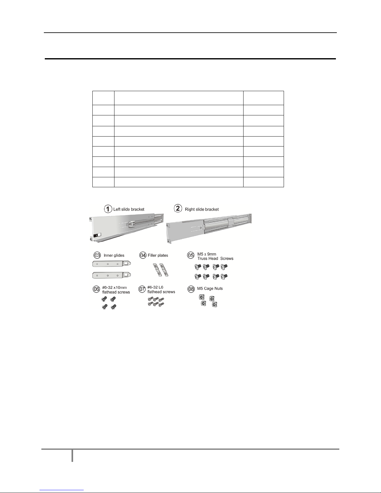
Step 2.Rack/Cabinet installation:If the subsystem is going to be installed in a rack or cabinet, it should
be installed prior to installing the hard drives. Installing the subsystem into a rack or cabinet requires at
least two (2) people.
Step 3. Install hard drives: Your purchased SAS / SATA-II/SATA-I hard drives have been pre-installed into
the drive trays. You will install them into the empty RAID chassis.
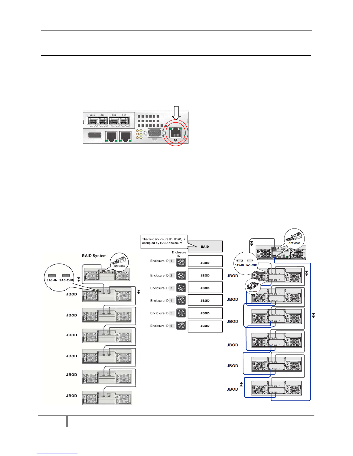
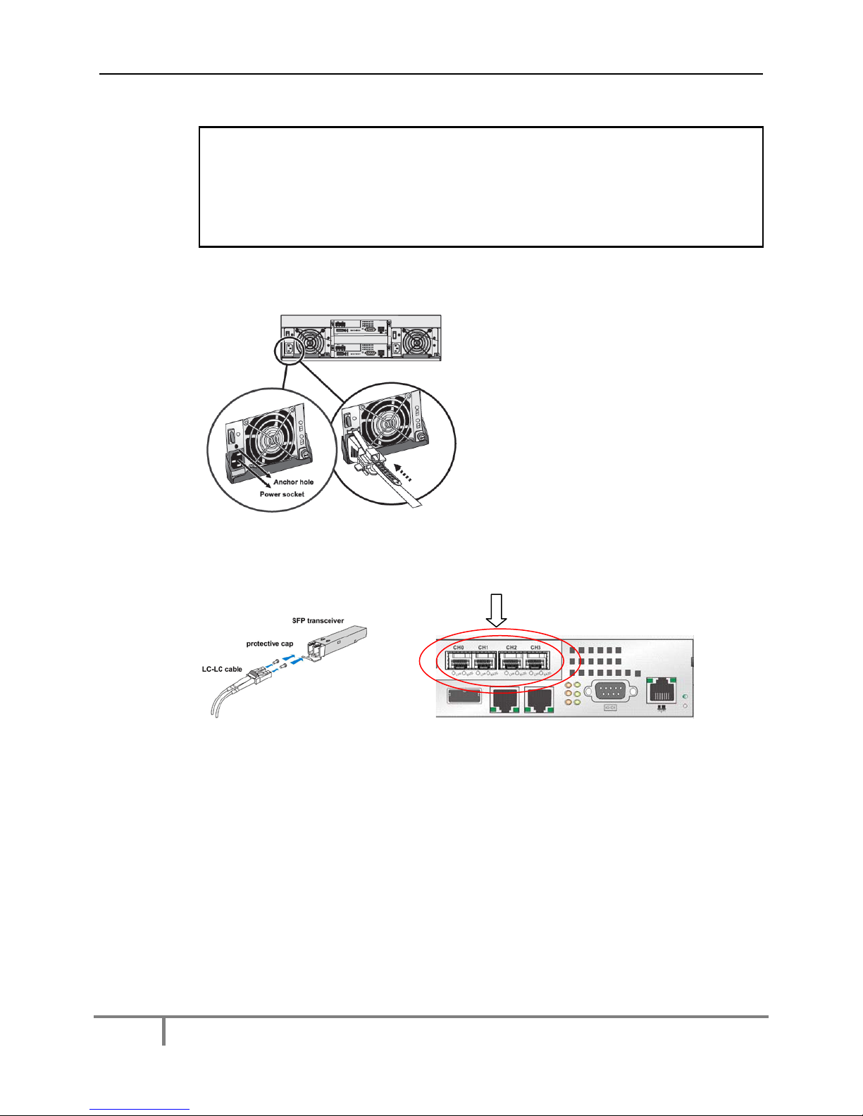
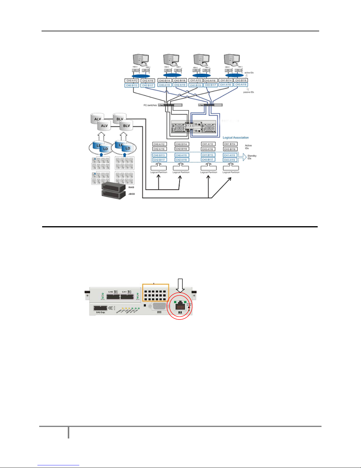
Step 4. Cable connection: Use the power cords that came with the subsystem to connect the subsystem
to the main power source. Use RJ-45 cables [not included] to connect host ports to the network.
Connect any host cables to switches, servers, workstations.
Step 5. Power up: Once the components have been properly installed and all cables are properly
connected, you can power up the subsystem and configure the RAID array.
Step 6. Bezel Installation:Use the hardware provided to put the chassis bezel in place
Step 7. RAID Management settings:Use the setup procedures to change your RAID settings.
Tools Required:

Galaxy HDX4 RAID Quick Install Guide
-2 -Contact Rorke Tech Support 800 328 8147
Step 1 Unpack the Subsystem
Static-free Installation
Static electricity can damage the system’s electronic components. To prevent ESD
damage to any of the components, follow these precautions before touching or handling
them:
Discharge the static electricity accumulated in your body by wearing an anti-static
wristband.
Use antistatic strap during handling. Connect the equipment end of the strap to
an unfinished chassis surface.
Avoid carpets, plastic, vinyl, and styrofoam in your work area.
If the need should arise for carrying subsystem modules from one place to
another, carry them in a static shielding container.
Avoid the contact between circuit boards and clothing.
Handle all components by holding their edges or metal frames. Avoid touching
the exposed circuitry on PCB boards and connector pins.
Unpack the Subsystem
Carefully unpack the containers and check the items contained in each box for shipping
damage before proceeding with installation..
One of the received boxed will contain the drive trays with drives installed
Another box will contain the Galaxy RAID chassis [ identified by having the distinctive
front LCD operator panel] and an accessory box containing power cords, JBOD cables,
documentation CD, mounting hardware and accessory items.
Additional boxes will contain other Galaxy JBODs, identified by having no front LCD
operator panel.
Preinstalled Components
The Galaxy RAID is ready to use except for the disk drives.
Components to be Installed
You must install the following components:
Rackmount rails if applicable
Drive trays [with drives pre installed ] install into the RAID chassis
Chassis bezel

Galaxy HDX4 RAID Quick Install Guide
-3 -Contact Rorke Tech Support 800 328 8147
Step 2 Rack Installation
Remove the rack rail hardware and follow the pictorial guide below:
1 Identify the components:
Item
Description
Quantity
01 Mounting bracket assembly, L-shape, left-side 1
02 Mounting bracket assembly, L-shape, right-side 1
03 Inner glide 2
04 Flange filler plate (fixed behind chassis ears) 2
05 Cross recess truss head screws M5 x 9.0mm 8
06 #6-32 x10mm flathead screws 4
07 #6-32 L6 flathead screws 6
08 M5 cage nuts 4
2 Measure Rail Locations in Rack:The mounting positions must be carefully
measured so that rails can be mounted parallel to each other. Move the rack clip nuts into
the positions shown for the front and rear posts. Note that the front cage nuts in position
3 and 7 will be used to hold the chassis in place

Galaxy HDX4 RAID Quick Install Guide
-4 -Contact Rorke Tech Support 800 328 8147
3Adjust Rail Length:Verify the rails are adjusted to the correct length by loosening the
4 screws and sliding the rear sections to meet the rear rack post. Tighten the screws
when done.
4Attach Rail to Posts:Secure the rail to the front and rear rack posts each using two
position screws. (See figure below) Do not insert the screws into the cage nuts as cage
nuts will be used to secure the enclosure later.
5Attach Bezel Filler Plate:Attach the bezel filler plates (#04) behind the enclosure
ears using the three #6-32 x 12mm flat head screws (#09) on each side.

Galaxy HDX4 RAID Quick Install Guide
-5 -Contact Rorke Tech Support 800 328 8147
6Attach Inner Glides to Chassis: Secure the inner glides (# 03) to the sides of the
chassis using the (#06) screws shown. Orient the glides so they inwards as seen from
the top of the chassis.
7Install Chassis into Rack: Two people should be used to lift and mount the chassis.
Match up the rack clip nuts and use the M5, M6 or #10-32 screws to secure the chassis
in place.

Galaxy HDX4 RAID Quick Install Guide
-6 -Contact Rorke Tech Support 800 328 8147
Step 3 Drive Installation
Carefully install the disk drives into the chassis. The drives can go into any empty
location and all locations must have a drive tray installed.
Note: If a “Cold Spare” was shipped, do not install this drive. Leave it in
it’s protective anti-static bag and put it in a secure place. Use it as a
defective drive replacement only.
1Prepare drive tray for installation: Use a small flatblade screwdriver to turn the drive
tray bezel lock to a horizontal position.
2Unlock the drive tray: Open the front bezel of the drive tray by pushing the release
button.
3Slide drive trays into place: Install the drives trays into the tray slots. Once installed
close the bezel until the release button secures the bezel in place. Rotate the bezel lock
to the vertical position to secure the drive tray into the slot.

Galaxy HDX4 RAID Quick Install Guide
-7 -Contact Rorke Tech Support 800 328 8147
Step 4 Cable Installation for Fibre Channel Hosts or SANs
Follow these steps to connect your management ethernet port, expansion
connections to add on RAID JBODs, power, and hosts to the Galaxy RAID.
1Management Interfacing: Use your CAT5E 100/1000 LAN cable to connect to the
management ethernet port on the rear of the Galaxy [ to the right of the DB9 connection] .
This port is used to manage and change the RAID configurations.
NOTE: THE MANAGEMENT PORT ADDRESS HAS BEEN PRESET TO 192. 168.1.129. IF THIS
CONFLICTS WITH YOUR SYSTEM CONTACT RORKE TECH SUPPORT OR SEE THE TECH
BULLETIN LOCATED ON THIS CD THAT SHOWS YOU HOW TO CHANGE YOUR IP ADDRESS
THROUGH THE FRONT OPERATOR PANEL.
2JBOD Interfacing: If your systems includes JBOD add-on chassis, you will need to
install SAS inter-chassis cables [ provided] as shown below. Refer to the detailed image
of the cable connection in Step 4-1 and install SAS cables according to the diagrams
below based on single or dual controllers. Set the ID setting of each JBOD to a different
ID using the rotary ID switch located under the JBOD’s front handle covers.

Galaxy HDX4 RAID Quick Install Guide
-8 -Contact Rorke Tech Support 800 328 8147
Note: 12 bay RAIDs require 12 Bay JBODs, 16 bay and 24 bay RAIDs require 16
bay JBODs. Refer the RAID hardware manual for specific information regarding
your specific JBOD configuration.
Also note that since 24bay RAIDs take address 0 and 1, the JBODs addresses need
to start with 2.
3AC Mains Cabling: Two AC cables are included and should be plugged into each of
the Galaxy Power Supply Units.
4 Host Cabling:
Install the SFP’s into each of the controllers FC ports. Remove the protective caps and
install the FC cables we have provided.
Although we can’t predict the exact way you will want to cable the Galaxy RAID into a
FC SAN, we have come up with a worse case diagram to show you how that would be

Galaxy HDX4 RAID Quick Install Guide
-9 -Contact Rorke Tech Support 800 328 8147
done in a dual controller configuration, below.
Step 4 Cable Installation for SAS Hosts
Follow these steps to connect your management ethernet port, expansion
connections to add on RAID JBODs, power, and hosts to the Galaxy RAID.
1Management Interfacing: Use your CAT5E 100/1000 LAN cable to connect to the
management ethernet port on the rear of the Galaxy [ to the right of the DB9 connection] .
This port is used to manage and change the RAID configurations.
NOTE: THE MANAGEMENT PORT ADDRESS HAS BEEN PRESET TO 192. 168.1.129. IF THIS
CONFLICTS WITH YOUR SYSTEM CONTACT RORKE TECH SUPPORT OR SEE THE TECH
BULLETIN LOCATED ON THIS CD THAT SHOWS YOU HOW TO CHANGE YOUR IP ADDRESS
THROUGH THE FRONT OPERATOR PANEL.
2JBOD Interfacing: If your systems includes JBOD add-on chassis, you will need to
install SAS inter-chassis cables [ provided] as shown below. Refer to the detailed image
of the cable connection in Step 4-1 and install SAS cables according to the diagram
below. Set the ID setting of each JBOD to a different ID using the rotary ID switch located
under the JBOD’s front handle covers.

Galaxy HDX4 RAID Quick Install Guide
-10 -Contact Rorke Tech Support 800 328 8147
Note: 12 bay RAIDs require 12 Bay JBODs, 16 bay and 24 bay RAIDs require 16
bay JBODs. Refer the RAID hardware manual for specific information regarding
your specific JBOD configuration.
Also note that since 24bay RAIDs take address 0 and 1, the JBODs addresses need
to start with 2.
3AC Mains Cabling: Two AC cables are included and should be plugged into each of
the Galaxy Power Supply Units.

Galaxy HDX4 RAID Quick Install Guide
-11 -Contact Rorke Tech Support 800 328 8147
4 Host Cabling:
Install the provided SAS cables into each of the controllers SAS ports.
Although we can’t predict the exact way you will want to cable the Galaxy RAID into a
SAS environment, we have come up with a worse case diagram to show you how that
would be done in a dual server configuration, below.
Step 4 Cable Installation for 10GbE iSCSI SANs
Follow these steps to connect your management ethernet port, expansion
connections to add on RAID JBODs, power, and hosts to the Galaxy RAID.
1Management Interfacing: Use your CAT5E 100/1000 LAN cable to connect to the
management ethernet port on the rear of the Galaxy [ to the right of the DB9 connection] .
This port is used to manage and change the RAID configurations.

Galaxy HDX4 RAID Quick Install Guide
-12 -Contact Rorke Tech Support 800 328 8147
NOTE: THE MANAGEMENT PORT ADDRESS HAS BEEN PRESET TO 192. 168.1.129. IF THIS
CONFLICTS WITH YOUR SYSTEM CONTACT RORKE TECH SUPPORT OR SEE THE TECH
BULLETIN LOCATED ON THIS CD THAT SHOWS YOU HOW TO CHANGE YOUR IP ADDRESS
THROUGH THE FRONT OPERATOR PANEL.
2JBOD Interfacing: If your systems includes JBOD add-on chassis, you will need to
install SAS inter-chassis cables [ provided] as shown below. Refer to the detailed image
of the cable connection in Step 4-1 and install SAS cables according to the diagram
below. Set the ID setting of each JBOD to a different ID using the rotary ID switch located
under the JBOD’s front handle covers.
Note: 12 bay RAIDs require 12 Bay JBODs, 16 bay and 24 bay RAIDs require 16
bay JBODs. Refer the RAID hardware manual for specific information regarding
your specific JBOD configuration.
Also note that since 24bay RAIDs take address 0 and 1, the JBODs addresses need
to start with 2.
3AC Mains Cabling: Two AC cables are included and should be plugged into each of
the Galaxy Power Supply Units.

Galaxy HDX4 RAID Quick Install Guide
-13 -Contact Rorke Tech Support 800 328 8147
4 Host Cabling:
NOTE: THE STANDARD IP ADDRESSES OF THE iSCSI PORTS ARE SET TO ‘DHCP’ TO MAKE
THEM MOST ACCEPTABLE BY MOST NETWORKS. iSCSI DRIVERS WILL NEED TO BE
INSTALLED ON ANY SYSTEM CONNECTING TO THE RAID AND SAN SHARING SOFTWARE
WILL NEED TO BE USED SO THE RAID DATA IS NOT CORRUPTED BY HAVING MULTIPLE
CLIENTS USING THE RAID. CONTACT RORKE TECH SUPPORT FOR DETAILS.
Although we can’t predict the exact way you will want to cable the Galaxy RAID into an
IP SAN, we have come up with a worse case diagram to show you how that would be
done in a dual controller configuration, below.
The first thing needed to be done is to install the optical SFP+s into the 10GbE ports on
the controllers. The user or Rorke will provide optical 10GbE cables that connect into the
SFP+s and will eventually connect through 10GbE switches to hosts. We strongly
suggest that if dedicated IP addresses are assigned, the same subnet be used by all.
Step 5 Power On
Follow these steps to power up and check the status of the Galaxy RAID.

Galaxy HDX4 RAID Quick Install Guide
-14 -Contact Rorke Tech Support 800 328 8147
Power on procedure.
•Make sure all the hardware components are properly installed.
•Power on all switches and networking devices.
•Power on all Galaxy JBOD enclosures by turning on the PSU power switches.
•Power on the Galaxy RAID enclosures by turning on the PSU power switches
•Power on the hosts servers or application stations.
•Check all the component LEDs. No drive, power, or fault LEDs, red or amber,
should be lit. The front panel of the Galaxy RAID should not have the ATTN LED
on, and will display the product number, ie GX4 –xxxxx along with a message
that says “Ready”.
Power off procedure.
Before you power off the Galaxy, The reverse of the steps to power on should be used to
power off the Galaxy RAID.
NOTE: ALL JBODS MUST STAY POWERED ‘ O N ‘ WHILE YOU POWER OFF THE GALAXY
RAID. ONCE THE RAID IS POWERED OFF, THEN POWER OFF THE JBODS! FAILURE TO DO
THIS MAY RESULT IN CORRUPT OR LOST DATA!
Status Indicators: Front of Enclosure
Observe the front of the Galaxy and verify the indicators below. If they are different or if
you hear an audible alarm, contact Rorke Tech Support at 800 328 8147.
LCD PANEL
LCD PANEL
PWR LED
ON [ BLUE]
OFF

Galaxy HDX4 RAID Quick Install Guide
-15 -Contact Rorke Tech Support 800 328 8147
Status Indicators: Rear of Enclosure
Observe the rear of the Galaxy and verify the indicators below. If they are different or if
you hear an audible alarm, contact Rorke Tech Support at 800 328 8147.
All Drive Trays
Power Status LED
Drive Busy LED
On [ Blue]
Blink [ Activity
Controller LEDS
CTRL STATUS
C_DIRTY LED
TEMP LED
CBM STATUS LED
On [ Green]
On or Off
Off
On or Off
Power Supply Unit LEDS
PSU LED
COOLING FAN LED
On [ Green]
Off

Galaxy HDX4 RAID Quick Install Guide
-16 -Contact Rorke Tech Support 800 328 8147
Front Panel Power on Status check procedure: [Refer to the Firmware Operations manual for
details on how to use the front LCD screen]
•Press the ENT key for 2 seconds to enter the Main Menu
•Use the arrow keys to move to the last menu,” View and Edit Events Logs”
•Press ENT to enter the menu
•Use the arrow keys to select an event
•Press ENT key for longer than 1 second on an event message, and use the
arrow keys to browse through the message lines
•Press ESC to return to the previous menu level, and press multiple times to exit
the menu.
10GbE LEDS
ACTIVITY LED
On [ Connected]
Blinking [Activity]
1GbE Administrator LEDS
LINK LED
ACTIVITY LED
On [ Connected]
Blinking [Activity]
Fibre Channel LEDS
LINK LED
8/4/2G
On [ Connected]
Blinking [Activity]

Galaxy HDX4 RAID Quick Install Guide
-17 -Contact Rorke Tech Support 800 328 8147
Step 6 Installing the RAID Bezel
The Galaxy comes with a bezel that protects the front of the RAID. Simple use the
thumbscrews on each side of the bezel and screw them to the rack mounted brackets
that were installed with the chassis.
Step 7 Opening Management Consoles
As we have stated, your Galaxy RAID has been configured and prepared for you, RAID
sets and LUNs already are prepared. All this is done in our effort to minimize the need
for any use of the management console during the installation. However, we know there
is going to be the need for you to use the management of the Galaxy so we have
included some basic information. Refer to the Web GUI and Galaxy Array Manager
manual for more details.
To use Web GUI through the management ethernet port, verify that the ethernet port on
the rear of the Galaxy RAID has a LAN connection cabled to it. Open a browser and key
in “http://192.168.1.129/index.html” . This will open the embedded Galaxy Web GUI and
you can view the statuses of the RAID, manage the RAID sets, partition the RAID, see
the status of the RAID and drives, etc.
To use Telnet through the management ethernet port, verify that the ethernet port on the
rear of the Galaxy RAID has a LAN connection cabled to it. Open a DOS prompt or
command shell and key in “telnet192.168.1.129” . This will open the embedded basic
Telnet session menus where you can view the statuses of the RAID, manage the RAID
sets, partition the RAID, see the status of the RAID and drives, etc.
To use any of the latest HDX4 advanced features such as replication, snapshots, and
thin provision, the java based Galaxy Array Manager [GAM] must be used. Refer to the
GAM manual for more details.

www.rorke.com Rorke Data, An Avnet Company
7626 Golden Triangle Drive, Eden Prairie, MN 55344, USA
» Toll Free 1.800.328.8147 » Phone 1.952.829.0300 » Fax 1.952.829.0988
Table of contents
Other Rorke Data Storage manuals

Rorke Data
Rorke Data Galaxy Aurora Series Quick setup guide

Rorke Data
Rorke Data Galaxy RAIDGHDX2-2130-16iSCSI User manual

Rorke Data
Rorke Data Galaxy A16F-G2422 User manual

Rorke Data
Rorke Data A16F-R2431 Galaxy Raid User manual

Rorke Data
Rorke Data Galaxy Aurora Series Quick setup guide

Rorke Data
Rorke Data Galaxy HDX2-2430S-16U4D User manual

Rorke Data
Rorke Data The Galaxy 65 User manual

Rorke Data
Rorke Data Galaxy GHDX2 ADA User manual