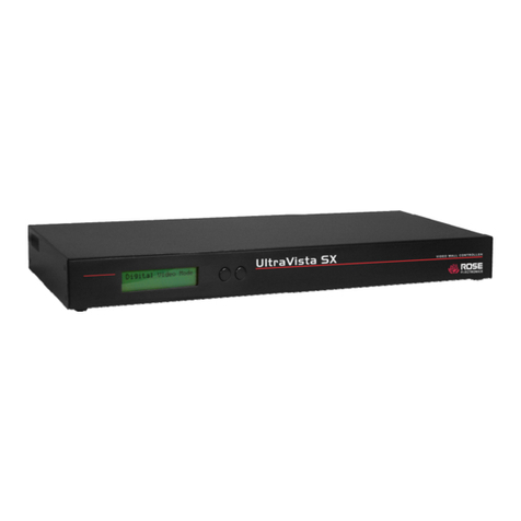
Rose electronics UltraVista 4K VWL-T222-4K-DVX User manual

UltraVista 4K
UHD Video Wall Controller • 4K30
Installation
and
Operation Manual
10707 Stancliff Road
Houston, Texas 77099
Phone: (281) 933-7673

LIMITED WARRANTY
Copyright Rose Electronics 2016. All rights reserved.
No part of this manual may be reproduced, stored in a retrieval system, or transcribed in any form or any means, electronic or mechanical, including photocopying and
recording, without the prior written permission of Rose Electronics.
manual-ultravista-4k30-2016-03-17
Rose Electronics®warrants the UltraVista 4K to be in good working order for one year from the date of
purchase from Rose Electronics or an authorized dealer. Should this product fail to be in good working order at
any time during this one-year warranty period, Rose Electronics will, at its option, repair or replace the Unit as
set forth below. Repair parts and replacement units will be either reconditioned or new. All replaced parts
become the property of Rose Electronics. This limited warranty does not include service to repair damage to
the Unit resulting from accident, disaster, abuse, or unauthorized modification of the Unit, including static
discharge and power surges.
Limited Warranty service may be obtained by delivering this unit during the one-year warranty period to Rose
Electronics or an authorized repair center providing a proof of purchase date. If this Unit is delivered by mail,
you agree to insure the Unit or assume the risk of loss or damage in transit, to prepay shipping charges to the
warranty service location, and to use the original shipping container or its equivalent. You must call for a return
authorization number first. Under no circumstances will a unit be accepted without a return authorization
number. Contact an authorized repair center or Rose Electronics for further information.
ALL EXPRESS AND IMPLIED WARRANTIES FOR THIS PRODUCT INCLUDING THE WARRANTIES OF
MERCHANTABILITY AND FITNESS FOR A PARTICULAR PURPOSE, ARE LIMITED IN DURATION TO A
PERIOD OF ONE YEAR FROM THE DATE OF PURCHASE, AND NO WARRANTIES, WHETHER EXPRESS
OR IMPLIED, WILL APPLY AFTER THIS PERIOD. SOME STATES DO NOT ALLOW LIMITATIONS ON HOW
LONG AN IMPLIED WARRANTY LASTS, SO THE ABOVE LIMITATION MAY NOT APPLY TO YOU.
IF THIS PRODUCT IS NOT IN GOOD WORKING ORDER AS WARRANTIED ABOVE, YOUR SOLE
REMEDY SHALL BE REPLACEMENT OR REPAIR AS PROVIDED ABOVE. IN NO EVENT WILL ROSE
ELECTRONICS BE LIABLE TO YOU FOR ANY DAMAGES INCLUDING ANY LOST PROFITS, LOST
SAVINGS OR OTHER INCIDENTAL OR CONSEQUENTIAL DAMAGES ARISING OUT OF THE USE OF OR
THE INABILITY TO USE SUCH PRODUCT, EVEN IF ROSE ELECTRONICS OR AN AUTHORIZED DEALER
HAS BEEN ADVISED OF THE POSSIBILITY OF SUCH DAMAGES, OR FOR ANY CLAIM BY ANY OTHER
PARTY.
SOME STATES DO NOT ALLOW THE EXCLUSION OR LIMITATION OF INCIDENTAL OR
CONSEQUENTIAL DAMAGES FOR CONSUMER PRODUCTS, SO THE ABOVE MAY NOT APPLY TO YOU.
THIS WARRANTY GIVES YOU SPECIFIC LEGAL RIGHTS AND YOU MAY ALSO HAVE OTHER RIGHTS
WHICH MAY VARY FROM STATE TO STATE.

DECLARATIONS OF CONFORMITY
This equipment has been tested and found to comply with the limits for a Class A digital device, pursuant to
Subpart J of Part 15 of the FCC Rules. These limits are designed to provide reasonable protection against
harmful interference when the equipment is operated in a commercial environment. This equipment generates,
uses, and can radiate radio frequency energy and, if not installed and used in accordance with the instruction
manual, may cause harmful interference to radio communications. Operation of this equipment in a residential
area is likely to cause harmful interference in which case the user will be required to correct the interference at
his own expense.

TABLE OF CONTENTS
Contents
Disclaimer 1
System Introduction 1
Features 1
Package Contents 2
Sample Application 3
Video Input Resolution for Models 3
UltraVista 4K Models 4
Model View 4
Front Views 4
Front View Connectors / Indicators 5
Rear View 6
Rear View Connectors /Indicators 6
Installation 7
Connections to the UltraVista 4K 7
Software Installation 8
UltraVista 4K Operation 11
Connection between Smart Editor and UltraVista 4K Unit 11
Connecting To and Disconnecting From the Unit(s) 11
Changing the IP of the Unit 12
Configuring the Video Wall 13
Screen Setup Area 13
Adjusting the Screens 16
Auxiliary Tools 17
Windowing Operations 18
Opening a Window 18
Closing a Window 18
Zooming a Window 18
Scrolling a Window 18
Cascading the UltraVista 4K 19
Safety 20
Maintenance and Repair 21
Technical Support 21

Figures
Figure 1. UltraVista 4K – Cascaded Video Wall displaying 1920x1080 on all monitors 3
Figure 2. UltraVista 4K Model View 4
Figure 3. Front View HDMI Model 4
Figure 4. Front View Dual-Link DVI Model 4
Figure 5. Front View DisplayPort Model 4
Figure 6. All models Rear View 6
Figure 7. Network Connections LAN Properties 7
Figure 8. Setting a Fixed IP address 8
Figure 9. Software Installation License Agreement 8
Figure 10. Software Installation Select Options Screen 9
Figure 11. Software Installation Select Destination Folder Screen 9
Figure 12. Software Installation Progress Screen 9
Figure 13. Smart Editor Desktop Icon 10
Figure 14. Smart Editor Main Screen 10
Figure 15. Connect to Units Screen 11
Figure 16. Change Device IP menu 12
Figure 17. Change Device IP Address Screen 12
Figure 18. Output Settings Main Screen 13
Figure 19. Output Screen Resolutions 13
Figure 20. Output Resolutions Advanced Timing 14
Figure 21. Output Screen Wall Configuration 14
Figure 22. Output Configuring the Video Wall 15
Figure 23. Output Dot Pitch and Bezel Compensation Settings 15
Figure 24. Output Screen Adjustment 16
Figure 25. Output Auxiliary Tools 17
Figure 26. Input Main Interface 18
Figure 27. Cascading Change Device Mode Window 19
Tables
Table 1. Supported Video Resolutions 3
Table 2. UltraVista 4K Specifications 22
Table 3. UltraVista 4K Part Numbers 22
Appendices
Appendix A - Specifications 22
Appendix B - Part Numbers 22

INTRODUCTION
UltraVista 4K Manual 1
Disclaimer
While every precaution has been taken in the preparation of this manual, the manufacturer assumes no
responsibility for errors or omissions. Neither does the manufacturer assume any liability for damages resulting
from the use of the information contained herein. The manufacturer reserves the right to change the
specifications, functions, circuitry of the product, and manual content at any time without notice.
The manufacturer cannot accept liability for damages due to misuse of the product or other circumstances
outside the manufacturer’s control. The manufacturer will not be responsible for any loss, damage, or injury
arising directly or indirectly from the use of this product. (See limited warranty.)
System Introduction
Thank you for choosing the UltraVista 4K. The UltraVista 4K is the result of Rose Electronics commitment to
providing state-of-the-art solutions for today’s demanding workplace. The UltraVista 4K Video Wall functions as
a tool to create and manage multiple screen video displays.
The UltraVista 4K is a comprehensive display wall processor. Single input signals are flexibly displayed on four
output displays. Each of these outputs may be DVI or VGA. The input image can be cropped to show any part
of it on an output display.Each display output can also be individually mirrored or rotated by 90°, 180° or 270°
to generate a mix of portrait and landscape oriented displays.
The UltraVista 4K is available in six models. Each model accepts one of three high-resolution video input
options: dual channel DVI, HDMI 1.4, or DisplayPort. The use of 4K resolution video inputs helps ensure
crystal-clear HD output to four DVI displays. Each video input model is available as a standalone unit or one
which supports cascading multiple units.
Features
■Supports one of three input types – dual-channel DVI, HDMI 1.4 or DisplayPort
■Three base models and three cascadable models, each supporting one of the input types
■Input resolutions up to 3840 x 2160 @ 30 Hz
■Four Full HD DVI video outputs with resolutions to 1920 x 1080 @ 60 Hz
■Each display output can be individually rotated or mirrored, for a mix of portrait and landscape oriented
displays
■Bezel compensation and overlap creation for edge blending
■Frame locking between cascaded units ensures a perfectly synchronized video wall
■Windows based software allows simple configuration control via IP or RS-232 connection
■EDID management provides for non-standard input resolutions

UltraVista 4K Manual 2
Package Contents
The package contents consist of the following:
■The UltraVista 4K unit as ordered
■1 x 12V Power Supply
■SmartEditor Software
■Manual
Additional cables are usually ordered separately. If the package contents are not correct, contact Rose
Electronics or your reseller so the problem can be quickly resolved.

SYSTEM OVERVIEW
UltraVista 4K Manual 3
Sample Application
Figure 1. UltraVista 4K – Cascaded Video Wall displaying 1920x1080 on all monitors
Video Input Resolution for Models
\
Video Input Supported Resolutions
Dual-Link DVI 4096*2160@30Hz, 3840*2400@30Hz, 3840*2160@30Hz, 1920*2160@60Hz, 2560*1600@60Hz.
HDMI 4096*2160@30Hz, 3840*2400@25Hz, 3840*2160@30Hz, 3840*2160@25Hz,
2560*1600@60Hz, 1920*2160@60Hz, 1920*2160@50Hz
DisplayPort 3840*2400@30Hz, 3840*2160@30Hz, 2560*1600@60Hz
Table 1. Supported Video Resolutions

MODELS
UltraVista 4K Manual 4
UltraVista 4K Models
Model View
Figure 2. UltraVista 4K Model View
Front Views
The UltraVista 4K comes in models with different input video options - dual-channel DVI, HDMI 1.4 and
DisplayPort. Each of these is displayed below.
Figure 3. Front View HDMI Model
Figure 4. Front View Dual-Link DVI Model
Figure 5. Front View DisplayPort Model

UltraVista 4K Manual 5
Front View Connectors / Indicators
HDMI 4K input interface - the LED to the right of the connector glows dimly when a HDMI
signal is detected
Dual-Link DVI input interface - the LEDs to the left of the connector glow when dual-link
video is detected
DisplayPort input interface - the LED to the left of the connector is always lit
RS-232 serial connector - Parameters: Baud Rate:9600, Data Bit: 8, Stop Bit: 0, Check Bit
1
RJ-45 connector for TCP/IP interface
Status Indicator LEDs – they all light up when power is applied to the unit; if the unit is
functioning normally, the lower left LED stays lit and the others turn off
Power barrel jack connector – 12V, 3.3A
Each UltraVista 4K unit accepts one input-signal source. This input-signal source opens a window on the
whole output splicing screen described below.

UltraVista 4K Manual 6
Rear View
Figure 6. All models Rear View
Rear View Connectors /Indicators
Ground connection
OUT1, OUT2, OUT3, OUT4 - DVI-I connectors for output video;
can be DVI or VGA signals
1, 2, 3, 4– Output Signal LEDs, light up when an output signal is
detected on the correspondingly numbered OUT port
Cascade Interfaces – IN is the cascade input signal and OUT is the
cascade output signal; connectors are only present on models
which support cascading
The UltraVista 4K unit 4 output signals which can be a DVI or a VGA signal. Each output signal can be
individually rotated by 90°, 180°,270°. The output signals can also be manipulated in any desired manner,
including splicing a portion of the image to an output signal, and moving or overlaying the output signals.

UltraVista 4K Manual 7
Installation
Installation of the UltraVista 4K is very simple. First make the necessary connections, and then install the
SmartEditor configuration software on a Windows based PC, laptop, or tablet.
Connections to the UltraVista 4K
Connect the appropriate video cables from the video source to the input connector on the UltraVista 4K.
Connect DVI cables from the unit’s output connectors to the appropriate displays. Apply power to the unit. For
a TCP/IP control interface, connect an Ethernet router or a crossover Ethernet cable between configuration PC
and the UltraVista 4K’s RJ-45 connector. Alternatively connect the configuration PC serially to the UltraVista
4K’s RS-232 connector.
TCP/IP Connection
The UltraVista 4K factory default IP address is 172.21.102.65. The control computer’s LAN connection should
be changed to a static IP address with a similar range to the UltraVista 4K. Once you have established a
connection to the UltraVista 4K, its IP address can be changed from the default address to one suitable for the
application environment.
On your computer, display the Local Area Connection Properties and highlight “Internet Protocol (TCP/IP)” and
click on the Properties tab.
Figure 7. Network Connections LAN Properties

UltraVista 4K Manual 8
When the Internet Protocol (TCP/IP) menu appears, click the radio button to select Use the following IP
address: and then enter the IP address 172 .21.102. x (where x is any value from 1 – 253), and Subnet mask:
255.255.255.0.
Figure 8. Setting a Fixed IP address
Click OK to confirm the change and exit.
Software Installation
Installing the software is easy. The steps are as follows.
1. Locate and run the installation file SmartEditor-x.x.x.x.exe. This will initiate the installation. The
installation interface is shown in the following figure.
Figure 9. Software Installation License Agreement

UltraVista 4K Manual 9
2. Clicking the I Agree button brings up the Installation Options screen.
Figure 10. Software Installation Select Options Screen
3. Select the desired options and click the Next > button to select the destination folder.
Figure 11. Software Installation Select Destination Folder Screen
4. Browse to the desired location and click the Install button. The installation progress screen is displayed.
Figure 12. Software Installation Progress Screen

UltraVista 4K Manual 10
5. If the software had been previously installed on the computer, a prompt will appear to first uninstall the
previous version of the software.
6. When the progress bar in the Software Install Progress Screen (Figure 12) shows that the installation is
complete, click the Close button to exit the software installation. If the Desktop Shortcut option was
selected in the Software Installation Select Options Screen (Figure 10), the following icon will be
displayed on the desktop.
SmartEditor
1.3.1.0
Figure 13. Smart Editor Desktop Icon
7. Double-click the desktop icon to display the main interface.
Figure 14. Smart Editor Main Screen
At this point installation is complete. Proceed to input and output configuration, as described in the following
section.

OPERATION
UltraVista 4K Manual 11
UltraVista 4K Operation
This section gives information on using the Smart Editor to set up and configure the video wall.
Connection between Smart Editor and UltraVista 4K Unit
In order to use the Smart Editor to communicate with the UltraVista 4K, a TCP/IP connection must be
established between them.
Connecting To and Disconnecting From the Unit(s)
The UltraVista 4K units available for connection are defined in the left hand side of the main screen. Enter the
number of units in the DeviceCount field, and click the Apply button. A list will be generated with the same
number of rows as the number of devices.
Figure 15. Connect to Units Screen
Select the device to connect to, and enter its IP address and port. The default IP address of an UltraVista 4K
unit is 172.21.102.65. Units can be named for easy identification. Once complete, click the Connect button to
establish the connection between the unit and the Smart Editor configuration PC.
Once a connection has been established, the Connect button changes to a Disconnect button. Click this button
to end the connection between the two.

UltraVista 4K Manual 12
Changing the IP of the Unit
To modify the IP address of a connected UltraVista 4K unit, right-click the unit definition in the list of devices.
Select the Change Device IP Address menu item from the popup menu.
Figure 16. Change Device IP menu
This brings up the Change Device IP Address screen where the network parameters of the unit can be set.
Figure 17. Change Device IP Address Screen
Make the necessary changes, and click the Apply button. If the Smart Editor cannot connect to the new IP
address, it will display an error message.

UltraVista 4K Manual 13
Configuring the Video Wall
The Video Wall is configured from the Output interface. This is accessed by clicking the Output button at the
top of the main screen.
Figure 18. Output Settings Main Screen
Here the video wall can be customized by rotating, splicing, and conducting other operations. These will be
described in this section.
Screen Setup Area
The Screen Setup Area is presented in the left hand side of the Smart Editor. This can be seen in Figure 18
shown above. The fields are described below.
Resolution:The UltraVista 4K supports up to 14 output screen resolutions.
Figure 19. Output Screen Resolutions

UltraVista 4K Manual 14
A resolution, once selected can be further customized by modifying its timing characteristic, by clicking the Adv
Timing button. This displays the Adv Timing screen where the timing characteristics can be changed.
Figure 20. Output Resolutions Advanced Timing
Add to Screen Wall: This set of fields provide the means to configure the screens as they will appear on the
Video Wall.
Figure 21. Output Screen Wall Configuration
The steps to configure the Video Wall are as follows.
1. Click on one of the white areas which represent a screen in the Video Wall. When it is selected, the
area turns black.
2. The drop-down box presents four angles by which to rotate the screen (0º, 90º, 180º, 270º).
3. Click the Add to Screen Wall button. The configured screen will be added to the working area on the
right hand side of the main screen.
4. Clicking the Reset button will delete the previous setting.
5. When the configuration is complete, click the Apply button to save the configuration.

UltraVista 4K Manual 15
This is displayed in the figure below.
Figure 22. Output Configuring the Video Wall
Screen Pixel Pitch and Bezel Border Width Compensation: The final set of fields defines the pixel pitch and
the bezel compensation for the monitors. These settings can be specified for each output or for the Video Wall
as a whole. Each is described below.
To change the settings for individual screens:
1. Select the screen whose pixel pitch and/or bezel compensation parameters are to be changed in the
left-hand side of the main interface.
2. This screen will turn green in the working area to indicate that it is being modified.
3. Modify the dot pitch and bezel compensation parameters, taking care to press the Enter key after each
parameter is changed.
4. When the changes to be made have been completed, click the Apply button in the Add to Screen Wall
field group.
Figure 23. Output Dot Pitch and Bezel Compensation Settings
This manual suits for next models
5
Table of contents
Other Rose electronics Controllers manuals
Popular Controllers manuals by other brands

Smartgen
Smartgen HGM9520N user manual

Grundfos
Grundfos CMB-SP PM1 instructions

Titan Controls
Titan Controls ATLAS 9 instruction manual

controlair
controlair 350 Series Installation, operation and maintenance instructions

Federal Signal Corporation
Federal Signal Corporation Signalmaster 330132 instruction sheet

IAI
IAI PSEL series First step guide