Rose electronics UltraVista 4K60 User manual

UltraVista 4K60
UHD Video Wall Controller • 4K60
Installation
and
Operation Manual
10707 Stancliff Road
Houston, Texas 77099
Phone: (281) 933-7673
tech-

LIMITED WARRANTY
Copyright Rose Electronics 2017. All rights reserved.
No part of this manual may be reproduced, stored in a retrieval system, or transcribed in any form or any means, electronic or mechanical, including photocopying and
recording, without the prior written permission of Rose Electronics.
manual-ultravista-4k60-2017-02-11
Rose Electronics®warrants the UltraVista 4K60 to be in good working order for one year from the date of
purchase from Rose Electronics or an authorized dealer. Should this product fail to be in good working order at
any time during this one-year warranty period, Rose Electronics will, at its option, repair or replace the Unit as
set forth below. Repair parts and replacement units will be either reconditioned or new. All replaced parts
become the property of Rose Electronics. This limited warranty does not include service to repair damage to
the Unit resulting from accident, disaster, abuse, or unauthorized modification of the Unit, including static
discharge and power surges.
Limited Warranty service may be obtained by delivering this unit during the one-year warranty period to Rose
Electronics or an authorized repair center providing a proof of purchase date. If this Unit is delivered by mail,
you agree to insure the Unit or assume the risk of loss or damage in transit, to prepay shipping charges to the
warranty service location, and to use the original shipping container or its equivalent. You must call for a return
authorization number first. Under no circumstances will a unit be accepted without a return authorization
number. Contact an authorized repair center or Rose Electronics for further information.
ALL EXPRESS AND IMPLIED WARRANTIES FOR THIS PRODUCT INCLUDING THE WARRANTIES OF
MERCHANTABILITY AND FITNESS FOR A PARTICULAR PURPOSE, ARE LIMITED IN DURATION TO A
PERIOD OF ONE YEAR FROM THE DATE OF PURCHASE, AND NO WARRANTIES, WHETHER EXPRESS
OR IMPLIED, WILL APPLY AFTER THIS PERIOD. SOME STATES DO NOT ALLOW LIMITATIONS ON HOW
LONG AN IMPLIED WARRANTY LASTS, SO THE ABOVE LIMITATION MAY NOT APPLY TO YOU.
IF THIS PRODUCT IS NOT IN GOOD WORKING ORDER AS WARRANTIED ABOVE, YOUR SOLE
REMEDY SHALL BE REPLACEMENT OR REPAIR AS PROVIDED ABOVE. IN NO EVENT WILL ROSE
ELECTRONICS BE LIABLE TO YOU FOR ANY DAMAGES INCLUDING ANY LOST PROFITS, LOST
SAVINGS OR OTHER INCIDENTAL OR CONSEQUENTIAL DAMAGES ARISING OUT OF THE USE OF OR
THE INABILITY TO USE SUCH PRODUCT, EVEN IF ROSE ELECTRONICS OR AN AUTHORIZED DEALER
HAS BEEN ADVISED OF THE POSSIBILITY OF SUCH DAMAGES, OR FOR ANY CLAIM BY ANY OTHER
PARTY.
SOME STATES DO NOT ALLOW THE EXCLUSION OR LIMITATION OF INCIDENTAL OR
CONSEQUENTIAL DAMAGES FOR CONSUMER PRODUCTS, SO THE ABOVE MAY NOT APPLY TO YOU.
THIS WARRANTY GIVES YOU SPECIFIC LEGAL RIGHTS AND YOU MAY ALSO HAVE OTHER RIGHTS
WHICH MAY VARY FROM STATE TO STATE.

DECLARATIONS OF CONFORMITY
This equipment has been tested and found to comply with the limits for a Class A digital device, pursuant to
Subpart J of Part 15 of the FCC Rules. These limits are designed to provide reasonable protection against
harmful interference when the equipment is operated in a commercial environment. This equipment generates,
uses, and can radiate radio frequency energy and, if not installed and used in accordance with the instruction
manual, may cause harmful interference to radio communications. Operation of this equipment in a residential
area is likely to cause harmful interference in which case the user will be required to correct the interference at
his own expense.

TABLE OF CONTENTS
Contents
Disclaimer 1
System Introduction 1
Features 1
Package Contents 1
Sample Application 2
Video Resolutions Supported 3
UltraVista 4K60 Model 4
Model View 4
Front View 4
Rear View 5
Installation 6
Connections to the UltraVista 4K60 6
Software Installation 6
Operation 7
Safety 15
Maintenance and Repair 16
Technical Support 16
Figures
Figure 1. UltraVista 4K60 –Video Wall displaying 1920x1080 on all monitors 2
Figure 2. UltraVista 4K60 4
Figure 3. Front View 4
Figure 4. Rear View 5
Figure 5. Connection Dialog Box 6
Figure 6. Connection Failure 6
Figure 7. Video Wall 4K60 Control Interface 7
Figure 8. Output Resolution Step 1 8
Figure 9. Quick Selection Menu 9
Figure 10. Load from File Menu 9
Figure 11. Image Adjustment Menu 10
Figure 12. Learn EDID Tab 11
Figure 13. Advanced Settings Tab 12
Figure 14. Factory Reset Prompt 12
Figure 15. Factory Reset Completion Screen 13
Figure 16. IP Configure Screen 13
Figure 17. Setting Up a Static IP on the UltraVista 4K60 13
Figure 18. Re-establish Connection to the UltraVista 4K60 After Configuration 14
Figure 19. UltraVista 4K60 IR Remote Control 19
Tables
Table 1. Supported Video Resolutions 3

Appendices
Appendix A – Specifications 17
Appendix B - Part Numbers 18
Appendix C - IR Remote Control 19

INTRODUCTION
UltraVista 4K60 Manual 1
Disclaimer
While every precaution has been taken in the preparation of this manual, the manufacturer assumes no
responsibility for errors or omissions. Neither does the manufacturer assume any liability for damages resulting
from the use of the information contained herein. The manufacturer reserves the right to change the
specifications, functions, circuitry of the product, and manual content at any time without notice.
The manufacturer cannot accept liability for damages due to misuse of the product or other circumstances
outside the manufacturer’s control. The manufacturer will not be responsible for any loss, damage, or injury
arising directly or indirectly from the use of this product. (See limited warranty.)
System Introduction
Thank you for choosing the UltraVista 4K60. The UltraVista 4K60 is the result of Rose Electronics commitment
to providing state-of-the-art solutions for today’s demanding workplace. The UltraVista 4K60 Video Wall
Processor functions as a tool to create and manage real-time multiple screen video displays.
The UltraVista 4K60 is a comprehensive video wall processor. An HDMI or DVI input signal is flexibly displayed
output to four HDMI or DVI displays. The input image can be cropped or zoomed to show any part of it on an
output display.Each display output can also be individually rotated to generate a mix of portrait and landscape
oriented displays.
The UltraVista 4K60 accepts HDMI or DVI signals. The use of 4K HDMI video input helps ensure crystal-clear
high definition video across the output displays.
Features
■Supports HDMI input from 640x480 to 4K2K@60HZ, or by adapter, DVI input to 1920x1200@60Hz
■Four Full HD DVI video outputs with resolutions to 1920 x 1200 @ 60 Hz
■Each display output can be individually rotated, for a mix of portrait and landscape oriented displays
■Windows based software allows easy configuration via IP or USB connection
■Stereo analog audio output to external speakers or digital output to speaker equipped HDMI displays
■EDID can be sourced from four internal default selections, from the remote displays, or from file
■IR remote control allows on the fly modification of output layout and audio volume
■Image parameters and layout are automatically saved in flash memory for recall
Package Contents
The package contents consist of the following:
■The UltraVista 4K60
■1U rack-mounting ear set
■12V 2A Power Supply
■Video Wall 4K60 software
■Manual
If the package contents are not correct, contact Rose Electronics or your reseller so the problem can be quickly
resolved.

SYSTEM OVERVIEW
UltraVista 4K60 Manual 2
Sample Application
Figure 1. UltraVista 4K60 –Video Wall displaying 1920x1080 on all monitors

UltraVista 4K60 Manual 3
Video Resolutions Supported
Input Resolution Output Resolution
720x480@30Hz
720x480@60Hz
720x576@30Hz
720x576@60Hz
1280x720@60Hz
1920x1080@30Hz
1920x1080@60Hz
4K2K@30Hz
4K2K@60Hz (4:2:0 10bits)
4K2K@60Hz (4:2:2 10 bits)
4K2K@60Hz (4:4:4 8bits)
640x480@60Hz
720x480@60Hz
720x576@60Hz
800x600@60Hz
1024x768@60Hz
1280x720@60Hz
1280x768@60Hz
1280x960@60Hz
1280x1024@60Hz
1366x768@60Hz
1440x900@60Hz
1680x1050@60Hz
1920x1080@60Hz
1920x1200@60Hz
1600x1200@60Hz
Table 1. Supported Video Resolutions

MODEL
UltraVista 4K60 Manual 4
UltraVista 4K60 Model
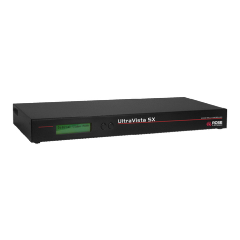
The UltraVista 4K60 is available in a single model as shown below.
Model View
Figure 2. UltraVista 4K60
Front View
Figure 3. Front View
■IR Sensor
■Power indicator
■Control buttons:
2x2 4K2K UHD layout
Recall custom layout (3 layout sets)
Recall original layout
Toggle between 1x1 and 2x2 layout
Toggle between 3x1 with –90º rotation and 3x1 with +90º rotation
Toggle between 4x1 with –90º rotation and 4x1 with +90º rotation

UltraVista 4K60 Manual 5
Rear View
Figure 4. Rear View
■Switch: Power ON/OFF
■12VDC: power adapter jack
■PROG: USB for firmware update and software configuration
■Ethernet: Ethernet port for software configuration
■Audio L: left channel analog audio
■Audio R: right channel analog audio
■HDMI IN: video input
■Normal F/W: dip switch for updating firmware; default position=1 (off)
■DVI OUT 1 - 4: video output

INSTALLATION AND OPERATION
UltraVista 4K60 Manual 6
Installation
Installation of the UltraVista 4K60 is very simple. First make the necessary connections, and then install the
Video Wall 4K60 software on a Windows based PC, laptop, or tablet.
Connections to the UltraVista 4K60
Connect the video source to the HDMI IN connector. If the source output is DVI, use a DVI to HDMI cable.
Connect the displays to the four DVI OUT connectors. If the displays require HDMI input, use DVI to HDMI
cables. Connect the +12VDC power supply to the power jack. Apply power to the unit.
NOTE: When power is removed from the unit, wait 10 seconds before reapplying it once again, so as to allow
the power capacitors to fully discharge.
Software Installation
Install the Video Wall 4K60 software on a computer running Microsoft Windows 98, 2000, XP, 7, or 8. The
software can communicate with the UltraVista 4K60 through a USB connection or through an Ethernet
connection. For a TCP/IP control interface, connect an Ethernet router or a crossover Ethernet cable between
configuration PC and the RJ45 connector of the UltraVista 4K60. Alternatively connect the configuration PC to
the UltraVista 4K60 mini USB PROG connector.
Note: Be sure to make the USB or Ethernet connection before running the software.
The first dialog pop-up displayed by the program allows the selection of either USB or Ethernet connections.
Figure 5. Connection Dialog Box
Select the appropriate connection type and details and click the green check mark. If the attempt to connect is
unsuccessful, an appropriate notification will be displayed.
Figure 6. Connection Failure
When the connection is successful, the main control interface will be displayed. This is described in the
Operation section below.

UltraVista 4K60 Manual 7
Operation
This section deals with how the Video Wall 4K60 software is used to set up and configure the display outputs
that make up the video wall.
Figure 7. Video Wall 4K60 Control Interface
Control Interface Components
Connection Status: Indicates the current connection type and status, for USB, for Ethernet
Quick Selection: Use this menu to set up screen resolution, coordinates, and screen layout. Click one
of the four colored display icons and drag within the image. The frame color within the image will match
the color of the icon clicked. The window coordinates will be displayed in the Horizontal and Vertical
Start and End boxes.
Rotation (only at 720p or 1080p output resolution):Rotate the selected frame 90º, clockwise or
counterclockwise.

UltraVista 4K60 Manual 8
Output Selection and Resolution:
a. Step1: View the current input resolution, and click a display icon to select the output port and set
its resolution. Changing an output’s resolution will change the coordinates displayed for that
output.
Figure 8. Output Resolution Step 1
b. Step2: Output settings can be selected through Quick Selection, from a file, or by a custom
definition. These corresponds to steps Step2_1, Step2_2 and Step2_3 respectively, as
described below.

UltraVista 4K60 Manual 9
i. Step2-1 (Output Settings through Quick Selection):Click the Step2-1 button and the Quick
Selection menu will be displayed. Select the screen splitting mode and rotation (rotation
requires 720p or 1080p output resolution). The 3x1 mode will divide the output into 3 parts,
with rotation; and the 4x1 mode divides it into 4 parts, also with rotation. When either of
these modes are selected, a white circle will be displayed on the output image. Sliding the
circle resizes the output screen. The screen size can also be specified by entering the
numerical coordinates.
NOTE: 4K2K60 (YUV 4:4:4) input can only be displayed in a 2x2 output layout, with each
output set to 1080p60.
Figure 9. Quick Selection Menu
ii. Step2-2 (Output Settings from file):If a settings file has been saved on the computer running
the software, click the Step2-2 button to load this file. Click the Load from File button to
select the desired file, and then click the Apply button.
Figure 10. Load from File Menu
iii. Step2-3 (Output settings through a custom definition):Click the Step2-3 button to perform a
define a customized portion of the input image for display on the output screen. Clicking on
the Grid selection button will cause a grid to be displayed on the input image, so as to
provide an accurate estimation of the output image. Click the Apply button to activate the
custom setting. Clicking the Save As button allows the configuration to be saved as a file on
the computer for future loading.

UltraVista 4K60 Manual 10
c. Step3: Click the Step3button to adjust the image. Clicking the Zoom In/Out and buttons
expand or contract the output image. Each click of the button modifies the image size by one
pixel. After adjustment, the rest of the image will be automatically scaled to fit the screen. The
image on each output can be shifted in a horizontal direction by clicking the and shift
buttons, or in a vertical direction by clicking the and shift buttons, moving one pixel per
button click.
Figure 11. Image Adjustment Menu

UltraVista 4K60 Manual 11
EDID (Extended Display Identification Data):There are three methods for setting the EDID used for the
video input: selecting one of the four options in the table of default values, acquiring the EDID from the
output monitors, and reading an EDID from a saved file.
Figure 12. Learn EDID Tab
To use one of the Default data sets, select the desired value from the pull down list and click the Learn
button. The preferred resolutions of the four default EDID values are:
Full-HD (1080p@60)-24bit 2D & 2ch
Full-HD (1080p@60)-24bit 2D & 7.1ch
4K2K@60-24bit 2D & 2ch
4K2K@60-24bit 2D& 7.1ch
To use an output display EDID, select the display from the pull down list and click the Learn button.
To load a data set from file, click the Load button to load in a selected file.
To review the specifics of a given EDID, select the source from the pull down menu and click the View
button.
To save an EDID as a file in the computer the software is running on, click the Save as… button.
NOTE: If different types of displays are used in the video wall, the best strategy is to learn the EDID of
the least capable display, especially when audio capable HDMI devices are part of the video wall.

UltraVista 4K60 Manual 12
Advanced Setting:Miscellaneous advanced settings such as providing a name for the unit, setting a
background splash screen and resetting the unit to factory defaults are performed here.
Figure 13. Advanced Settings Tab
To provide a name to the UltraVista 4K60 unit to aid in identifying it, enter up to 8 characters in the New
Host Name field, and click the button.
To change the default splash screen used by UltraVista 4K60, click the Load Graph button, select the
image desired, and click the button to save the image to the unit.
To reset the UltraVista 4K60 to factory default settings, click the button. A
confirmation pop up will be displayed.
Figure 14. Factory Reset Prompt

UltraVista 4K60 Manual 13
NOTE: Restart the UltraVista 4K60 when the completion box is displayed.
Figure 15. Factory Reset Completion Screen
IP CONFIGURE: To change the IP address used by the unit, click the IP CONFIGURE button. To read
the current device setting, click the Read from device button.
Figure 16. IP Configure Screen
Modify the IP address as desired, and click the Write to device button.
Figure 17. Setting Up a Static IP on the UltraVista 4K60
To have the IP address assigned dynamically by a server, click the DHCP box.
NOTE: After setting the IP address as desired. restart the UltraView 4K60 for the changes to take
effect.
INFO: Click the INFO button to view the UltraView 4K60 software and the device firmware version
numbers.

UltraVista 4K60 Manual 14
REFRESH: To update the settings information, and to reconnect to the device, click the REFRESH
button. The ReConnectForm window will be displayed, allowing the user to restart the configuration
connection.
Figure 18. Re-establish Connection to the UltraVista 4K60 After Configuration

PRODUCT SAFETY
UltraVista 4K60 Manual 15
Safety
The UltraVista 4K, like all electronic equipment, should be used with care. To protect yourself from possible
injury and to minimize the risk of damage to the Unit, read and follow these safety instructions.
Follow all instructions and warnings marked on this Unit.
Except where explained in this manual, do not attempt to service this Unit yourself.
Do not use this Unit near water.
Assure that the placement of this Unit is on a stable surface.
Provide proper ventilation and air circulation.
Keep connection cables clear of obstructions that might cause damage to them.
Use only power cords, power adapter and connection cables designed for this Unit.
Keep objects that might damage this Unit and liquids that may spill, clear from this Unit. Liquids and
foreign objects might come in contact with voltage points that could create a risk of fire or electrical
shock.
Do not use liquid or aerosol cleaners to clean this Unit. Always unplug this Unit from the power source
before cleaning.
Remove power from the Unit and refer servicing to a qualified service center if any of the following conditions
occur:
The connection cables are damaged or frayed.
The Unit has been exposed to any liquids.
The Unit does not operate normally when all operating instructions have been followed.
The Unit has been dropped or the case has been damaged.
The Unit exhibits a distinct change in performance, indicating a need for service.
This manual suits for next models
1
Table of contents
Other Rose electronics Controllers manuals
Popular Controllers manuals by other brands

ABB
ABB RHDE250 operating instructions

KMTRONIC
KMTRONIC U1CRBD user guide

Rockwell Automation
Rockwell Automation Allen-Bradley Micro800 instruction manual

FIBARO
FIBARO THE BUTTON quick start guide

Panasonic
Panasonic AWRP655N - MULTI FUNCTION CONTROLLER operating instructions

Toshiba
Toshiba TS2000 instruction manual