2
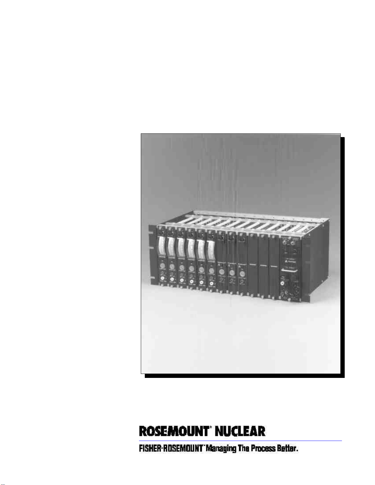
Model 710DU Trip/Calibration System
•Qualified per IEEE Std 323-1974 and
IEEE Std 344-1975
•Use with 4–20 transmitters or 3-wire
100 Vplatinum RTD’s
•Exceptional reliable modular design
•Up to 8 precision trip points per signal
FEATURES
Rosemount® Model 710DU Trip/Calibration
Systems continuously monitor critical process
parameters and provide highly accurate alarm
action. As many as eight precision-calibrated trip
points can be assigned to a single sensor channel.
Any trip point can be quickly verified or changed.
The system consists of a card file with a plug-in
calibration unit and space for up to 12 interchangeable
trip unit modules. These features make Model 710DU
Systems highly flexible, simple to install or reconfigure,
and easy to calibrate.
OPERATION
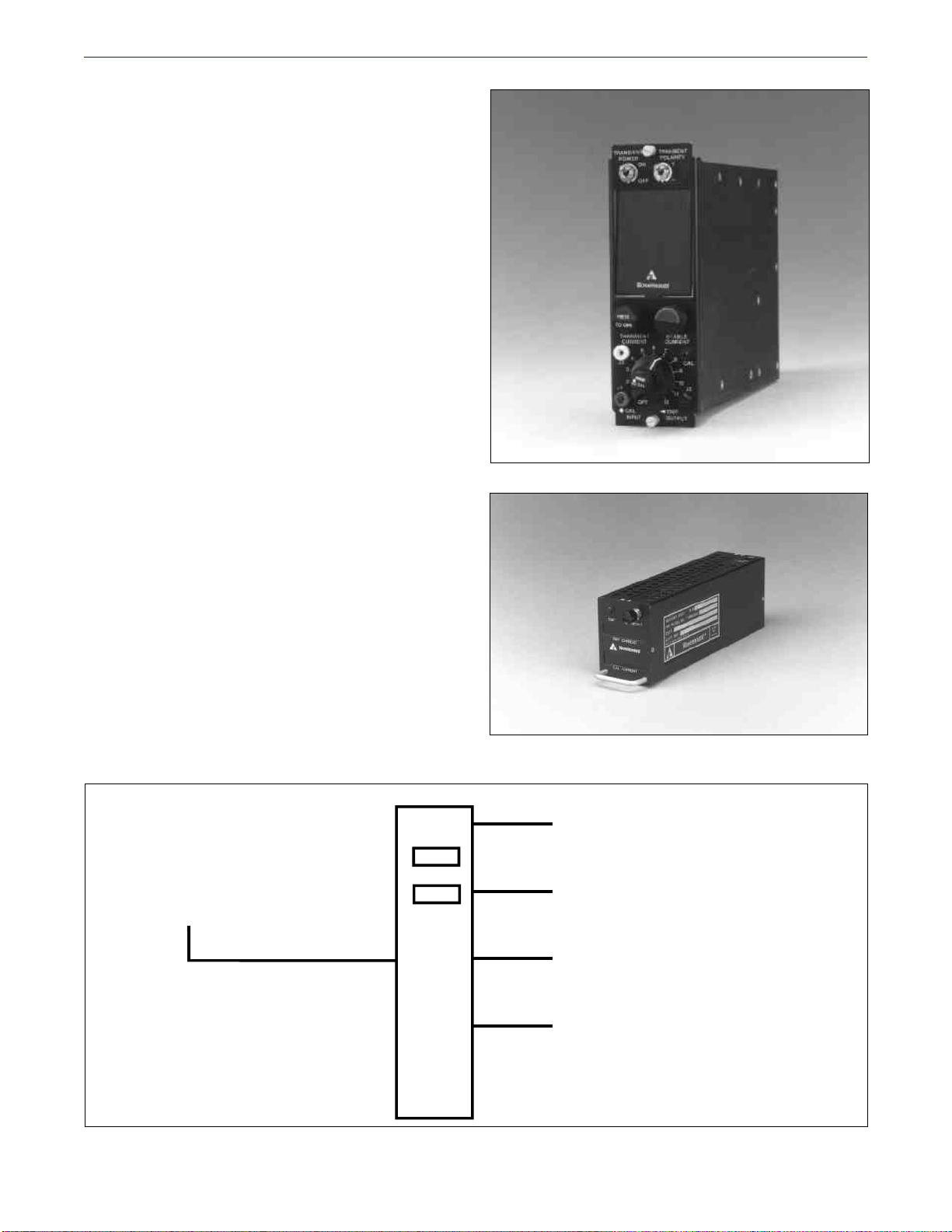
Trip Unit
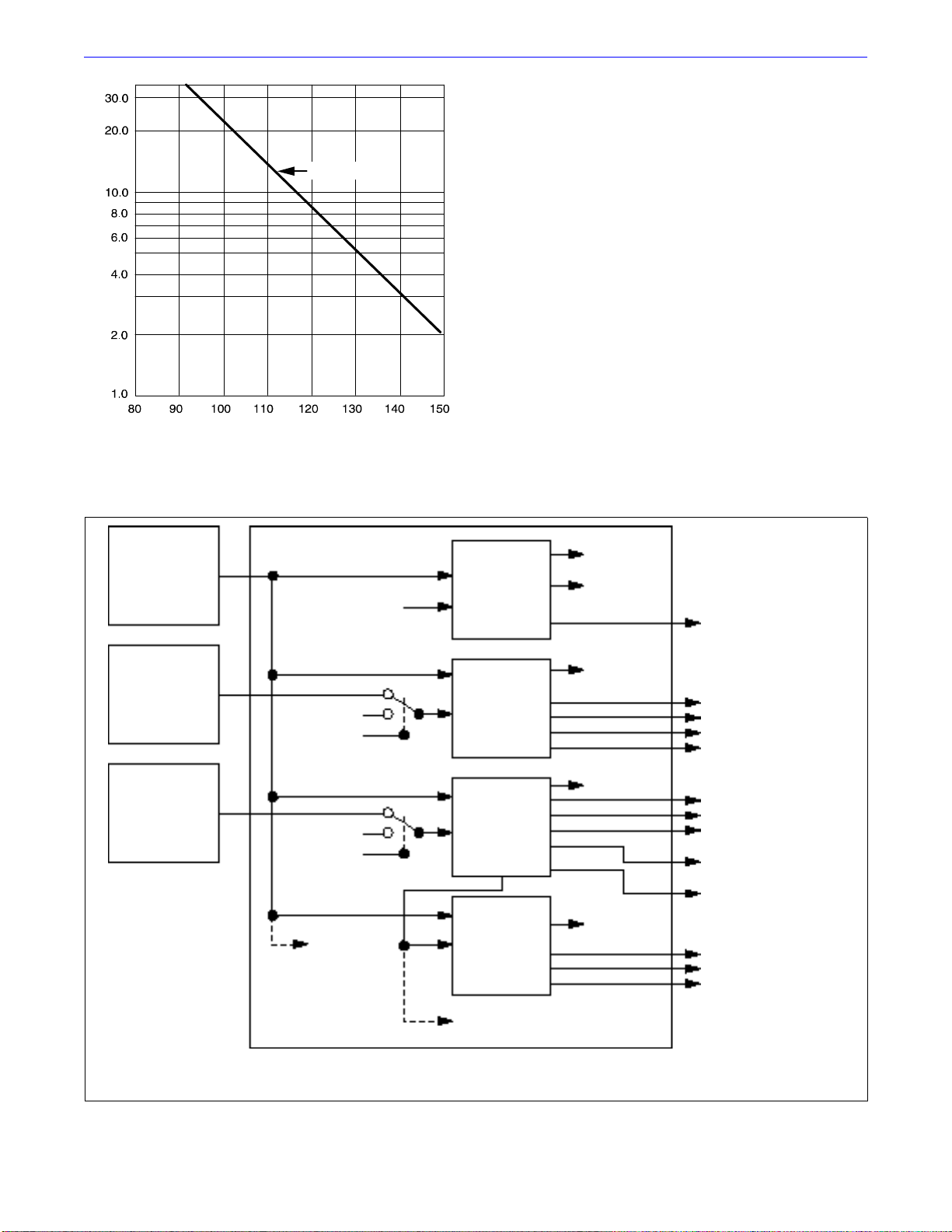
One master trip unit is required for each 4–20 mA
transmitter or RTD input. A basic master trip unit
displays the sensor output, provides one high or low
trip circuit, a high/low gross failure circuit, and a
proportional analog output for driving up to seven
slave trip units.
Each slave adds one additional trip point and gross
failure circuit to the transmitter loop. The trip
output of any master or slave trip unit can drive an
external relay. The auxiliary analog output of the
master trip unit can be used to drive an external
proportional controller or recorder.
The trip point circuit features precision external
adjustment with either high or low nonlatching trip
action. The gross failure circuits are internally
adjustable with manual reset high and low trip
action. Trip point and gross failure indicating lamps
are furnished on each trip unit.
Calibration Unit
The trip point for any master or slave trip unit
within the card file can be read or accurately
calibrated by the calibration unit. This unit provides
space for a unique digital readout assembly and
permits the operator to automatically replace the
field transmitter input signal to any channel with a
precisely adjustable calibration signal. This enables
the trip point to be compared exactly with the
desired input signal level. After the trip points for all
channels within the file have been set, the readout
assembly can be removed and plugged into any other
calibration unit.
Applications
Model 710DU trip/calibration systems are ideally
suited to nuclear power applications or any process
where frequent calibrations of trip points are
essential. Critical process trip points are repeatable
within 0.13% of span for 4–20 mA transmitter inputs
and 0.75% of span for RTD inputs under normal
conditions. System components have been qualified
per IEEE Std 323-1974 and IEEE Std 344-1975 as
stated in Rosemount Qualification Reports
D8200037 and D8300112.
Rosemount and the Rosemount logotype are registered trademarks of
Rosemount Inc.
Cover Photo: 710-001AB