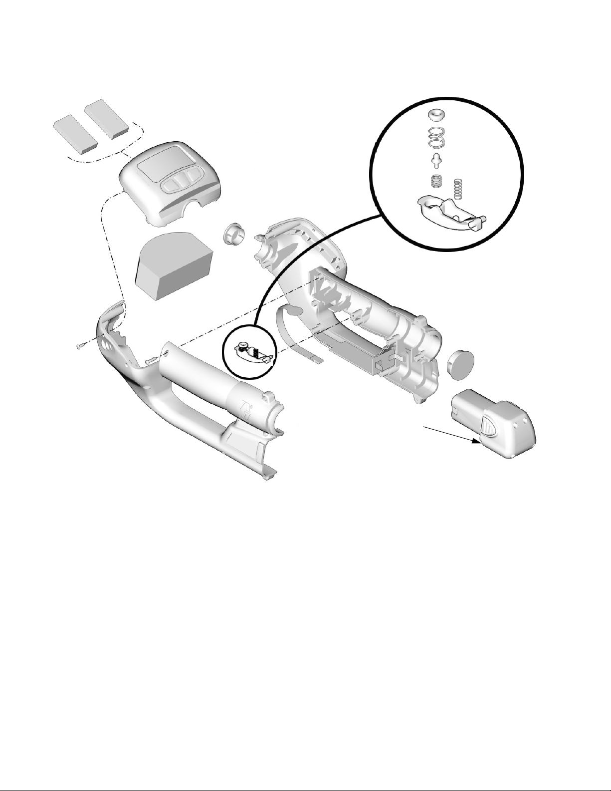
Operation
311002C 7
GOOD SIGNAL: If over several test intervals the result
is consistently a GOOD SIGNAL, the location is within
the range of the Transceiver for reliable communication.
BAD SIGNAL: If the results are consistently a BAD SIG-
NAL, (despite an occasional GOOD SIGNAL reading),
the location is not within the range of reliable Trans-
ceiver communication.
3. Pressing the RF Tester trigger again resets the tes-
ter to zero and restarts the testing.
LOCATING THE TRANSCEIVER(S)
Perform RF signal testing at all Meter and TLM locations
to determine an appropriate mounting location for the
Transceiver(s).
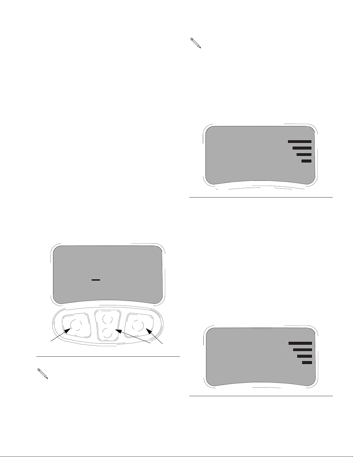
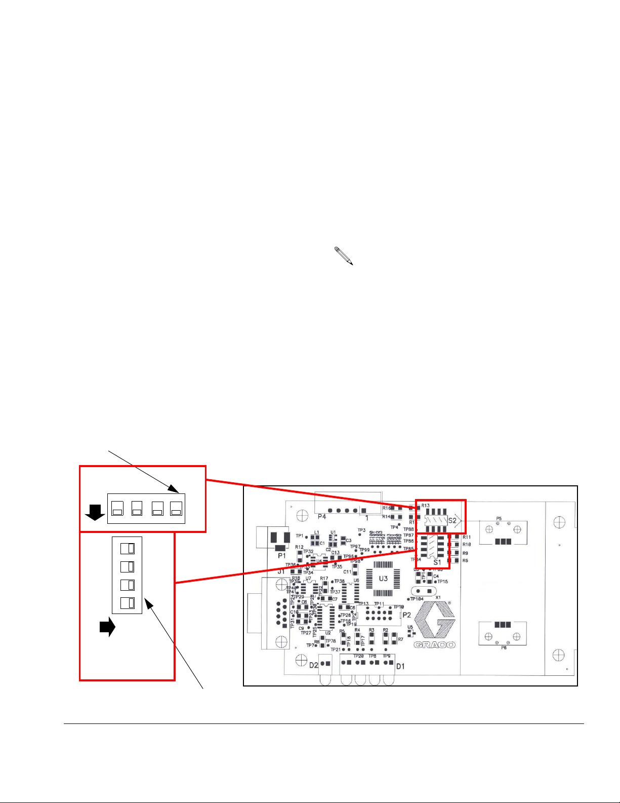
Optional Display Information
The number of retries for each test interval is used to
calculate if the return signal is a GOOD SIGNAL or a
BAD SIGNAL. This optional/additional information can
be displayed if desired for signal troubleshooting/analy-
sis. It is not necessary to display this information for
general RF Signal testing.
On/Off
Optional information is displayed by pressing the up
center button (C) during the RF signal testing process.
Pressing the down center button (C) during the RF sig-
nal testing process hides this information. See FIG. 7.
Optional Display Information Explanation
Each test interval sends 10 messages to the Trans-
ceiver. Each of these 10 messages is resent up to 10
times or until the RF tester receives a response from the
Transceiver. If no response is received after resending
the individual message 10 times the RF tester moves on
to the next text message and resends it up to 10 times
or until a response is received from the Transceiver.
Once all 10 test interval messages have been sent and
RF testing is complete, the number of retries for each of
the 10 messages is totaled (anywhere from 1-100) and
then divided by 10 to get the AVG. RETRIES number.
This number is displayed on the RF tester screen.
For example, FIG. 7 illustrates an RF interval test where
a total of 50 resend messages were bad out of a possi-
ble 100 (10 test interval messages x 10 retries = 100)
100 ÷ 50 = 5.
A test interval that has an AVG. RETRIES of 4 or more
is considered a BAD SIGNAL. An average of less than 4
is considered a GOOD SIGNAL.
Pressing the trigger anytime during the test stops
the testing at the last message sent. Pressing the
RF tester trigger again resets the tester to zero and
restarts the testing.
If a Transceiver needs to be repositioned or
another Transceiver needs to be added to the sys-
tem, be sure to repeat RF signal testing at all Meter
and TLM locations in the facility to assure reliable
RF communication from the new Transceiver loca-
tion(s).
FIG. 7
BAD SIGNAL
MSGS SENT 10
AVG. RETRIES 5
C