Hirel HH972 User manual
D
Di
ig
gi
it
ta
al
l
P
Po
oc
ck
ke
et
t
O
Os
sc
ci
il
ll
lo
os
sc
co
op
pe
e
H
HH
H9
97
72
2
O
OP
PE
ER
RA
AT
TI
IN
NG
G
M
MA
AN
NU
UA
AL
L
Rev. A.5
H
H
H
H
9
9
7
7
2
2
S
S
T
T
9
9
7
7
2
2
M
M
e
e
t
t
e
e
r
r
M
M
o
o
d
d
e
e
O
O
s
s
c
c
i
i
l
l
l
l
o
o
s
s
c
c
o
o
p
p
e
e
M
M
o
o
d
d
e
e

HH972 Operating Manual p 2/12
TABLE OF CONTENTS
TITLE PAGE
1. Safety instructions............................................................................................................3
-A- General safety informations.............................................................................................3
-B- Extreme caution to avoid electrical damage to the scope ..................................................3
2. FCC informations for the USA........................................................................................3
3. Pocket Scope overview......................................................................................................4
-A- General .............................................................................................................................4
-B- Front panel........................................................................................................................4
-C- Back panel ........................................................................................................................5
4. How to operate the HH972................................................................................................5
-A- Test Leads........................................................................................................................5
-B- OSCILLOSCOPE mode................................................................................................ 5-6
-C- Measure tools...................................................................................................................6
§Horizontal cursors (amplitude)
§Vertical cursors (time)
-D- Manual settings of scales............................................................................................. 6-7
-E- DC offset control..............................................................................................................7
-F- MENU selection........................................................................................................... 7-8
-G- METER mode ..................................................................................................................9
5. ST972 STAND with rechargeable battery.................................................................. 9-10
6. Specifications...................................................................................................................11
WARRANTY
This instrument and accessories have a limited warranty against defects in material and
workmanship for a period of one year from the date of sale. During the warranty period,
Hirel Corporation or local representatives will repair or replace if products prove to be
defective. Warranty shall not apply to defects resulting from tampering, abuse or
mishandling. In such case the repair will be billed at the nominal cost. Any other cost
directly or indirectly connected to the repair shall not be reimbursed.
For warranty service or repair, this instrument or accessories must be returned to a
service facility or a local representative designated by Hirel.
Buyer shall prepay shipping charges to Hirel or its local representative, Hirel or its local
representative shall pay shipping charges to return it to buyer.
RESPONSIBILITY
Hirel or local representatives shall not be liable for incidental or consequential damages
in connection with, or resulting out of the furnishing, performance, or use of the
material described in this document.
Hirel represented by:
955 B
ERKSHIRE
A
VENUE,
SUNNYVALE, CA 94087
TEL (1) 408-773-2767
FAX (1) 408-773-2781
e-mail: [email protected]
website: www.merictech.com

HH972 Operating Manual p 3/12
1. Safety instructions
-A- General safety informations
Before using the HH972 oscilloscope and its accessories, read the following safety
instructions carefully. This instrument is designed to observe electrical signals and some
conditions and actions may present some hazards to the user.
§To avoid electrical shock:
•Use caution when working above 60V DC or 30V AC RMS, such voltages pose a
shock hazard.
•Use caution when connecting the AC ADAPTER to the power lines.
•Do not use defective test leads.
•Do not operate with battery cover removed. Before removing cover, disconnect test
leads, turn off power by releasing the POWER button, and remove the AC adapter
jack from the unit.
§Use only the AC ADAPTER provided with the scope or the ST972 BATTERY STAND
to supply the HH972 unit. Use only the same adapter to charge the ST972 or ST972-EC
internal 9V battery.
§Never permit water to enter the interior of the instrument and accessories and never subject
them to severe mechanical shock.
§The ST972 and ST972-EC optional STAND accessories are only for use with the HH972
oscilloscope.
-B- Extreme caution to avoid electrical damage to the scope
§Do not apply electrical live sources between A and K terminals. Before attempting in-
circuit testing, turn-off power to the test circuit and discharge all capacitors.
§Do not apply input voltage more than + or - 400V DC and 800V peak to peak AC between
V and COM terminals.
2. FCC informations for the USA
Introduction: This equipment has been tested and found to comply with the limits for a
Class B digital device, pursuant to Part 15 of the FCC rules. These limits are designed to
provide reasonable protection against harmful interference in a residential installation. This
equipment generates, uses and can radiate radio frequency energy and, if not installed and
used in accordance with the instructions, may cause harmful interference to radio
communications. However there is no guarantee that interference will not occur in a particular
installation. If this equipment does cause harmful interference to radio or television reception,
which can be determined by turning the equipment off an on, the user is encouraged to try to
correct the interference by one or more of the following measures:
§Reorient or relocate the receiving antenna.
§Increase the separation between the equipment and receiver.
§Connect the equipment into an outlet on a circuit different from that to which the receiver
is connected.
§Consult the dealer or an experienced radio/TV technician for help.
Modifications: The FCC requires the user to be notified that any changes or modifications
made to this device that are not expressly approved by the Manufacturer may void the
user’s authority to operate the equipment.

HH972 Operating Manual p 4/12
3. Pocket Scope overview
-A- General
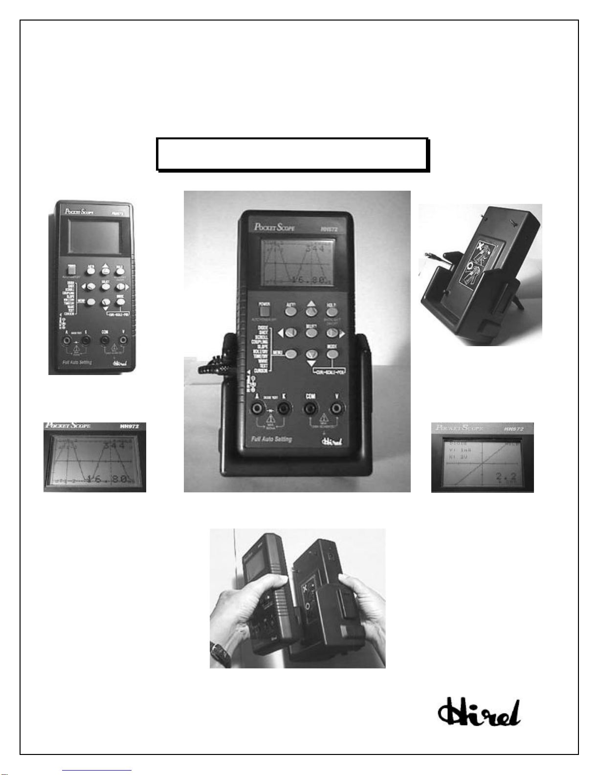
The HH972 combines a digital oscilloscope with a multimeter. It offers the advanced features
of an auto-set digital oscilloscope and a component curve tracer, in the size and for the price of
a hand-held multimeter (3.6” x 7.1” x 1.4” (180 x 90 x 35 mm) / 12.7 oz (360g) with
battery). It is equipped with a high contrast backlit LCD display with a wide-angle visibility
(150(H) x 100(V) dots).
It has been designed to satisfy a wide range of requirements, from experts to novices, in
homes, offices, laboratories, and in the field:
§Scope mode to observe voltage waveform from an active electric / electronic source.
§Meter mode to check a possibly damaged discrete or in-circuit component. It can also help
test resistors or trace open/shorts in failing systems.
§280V true RMS AC / + or – 400V DC maximum input voltage.
§5MHz bandwidth (Digital sampling @20Ms/sec).
§Full auto setup / auto adjust / auto display of amplitude and time.
§Easy access to functions with front keys. HOLD key to freeze the display.
§3-hour continuous operations with a 9V battery or 10-hours with the optional ST972 stand
including a rechargeable battery.
§Test leads included (test probe not required).
Because of its low cost, small size and technical performances, the HH972 is well suited for
educational purposes. Applications cover digital and analog signals, telecommunication, GPS,
TV and audio, line-operated equipment, sensors, signal analysis in automotive (with optional
ST972-EC), car stereo etc. It is especially convenient for technicians installing and
maintaining equipment, working by themselves far from their factory, far from power sources.
-B- Front side
Feature Function
POWER Press ON or OFF to get scope powered or turned off.
AUTO Auto ranging to get best fit in the display
Use to manually change settings.
SELECT 1- Swapping synchro from (+) slope to (-) slope
2- Selection of cursor #1 or #2
HOLD Press once to freeze the display for observation.
Press again to return to RUN mode
When depressed for > than 2s, display light gets turned on
When depressed again for > than 2s, light gets turned off.
MENU Access to menu to change default settings
Use to change settings.
MODE 1- CURSOR to display amplitude and time
2- SCALE mode to adjust scale factors
3- OFFSET mode to change DC offset settings.
A-K
terminals METER mode for continuity testing.
COM-V
terminals OSCILLOSCOPE mode.

HH972 Operating Manual p 5/12
BATTERY
COVER
SCREW
BATTERY
COVER
9V
BATTERY
BATTERY CONNECTOR
AUTO fRUN
50 µs 50mV
Figure 1
-C - Back side
To install or replace the 9V battery proceed
as follow:
§After disconnecting test leads, and
turning off the oscilloscope, remove
the battery cover screw.
§Disconnect battery from instrument
and replace with a 9V alkaline
battery. Or simply install the new
battery for the first time.
§Replace back cover and secure with
one screw.
Warning:
Use 9V alkaline batteries only. The HH972 wouldn’t properly work with any other type.
4. How to operate the HH972
-A- Test Leads/ Input terminals
OSCILLOSCOPE mode:
To observe voltage waveform from an active electric / electronic source, attach test leads to
the scope. Connect the black test lead to COM-labeled black terminal and the red one to V-
labeled red terminal.
Warning: any mismatch can cause erroneous analysis.
METER mode:
To check continuity of a discrete or in-circuit component, connect the black test lead to K-
labeled black terminal. and the red one to A-labeled red terminal.
Warning: do not apply live electrical sources between A and K terminals.
-B- Operating the HH972 in OSCILLOSCOPE mode
To start measurement, press the POWER button.
Connect test leads across the electrical source to analyze.
The HH972 automatically adjusts time and amplitude
scales to best fit the incoming signal and displays the
captured waveform. "AUTO" may be seen in the upper
left corner of the display, meaning that the unit is in
AUTO mode, in which, time and amplitude scales are
automatically optimized.
The time and amplitude scales are shown along the lower
edge of the display (50 µsec and 50mV in the example of Fig.1). "fRUN" in the upper right
corner means that the HH972 is continuously catching and displaying the incoming signal.
For a clear view of the waveform, press the HOLD button. This causes the HH972 to store
and display the waveform just captured. The mark "fRUN" changes to "fHOLD".
HH972 Operating Manual p 6/12
CUR . 1 fRUN
V1 2 108mV∆
∆TI -2
102.0 µs
Figure 2
Depressing the HOLD button allows the user to alternate between capture and observation as
instructed on the screen ("Press HOLD again for another capture" / "Press HOLD for clear
view").
-C- Measure tools
To access CURSOR mode and adjust positions and values, use the following keys:
MODE button: used to display cursor lines and values of signal amplitude and time.
In this mode, the cursor lines can be manually adjusted to desired locations.
SELECT button: used to select cursor # 1 or cursor #2 to be moved. While selected,
the cursor can be moved with in both AUTO and HOLD modes ( /for
amplitude, / for time).
While running in AUTO mode, press the MODE button once, 4 cursor lines appear (Fig.2):
- 2 horizontal lines parallel to time scale (X-axis),
- 2 vertical lines parallel to amplitude scale (Y-axis).
§Horizontal cursors (amplitude)
The 2 cursor lines parallel to X-axis are automatically placed to show the peak to peak
amplitude of the incoming waveform. If the incoming signal fluctuates in amplitude, these 2
lines move up and down accordingly. The peak to peak distance between these 2 cursor lines
is denoted as V1-2 and its value is displayed in the upper right corner of the LCD panel
(108mV as shown in Fig.2.)
These 2 cursors could also be manually adjusted to measure the amplitude of any part of the
signal. (similar operation than the one explained in the following time scale section)
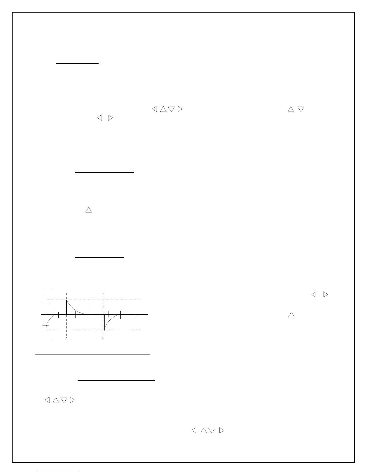
§Vertical cursors (time)
The 2 « time » vertical cursor lines are to be settled manually to measure time length.
Press the HOLD button (measurement is usually easier
when performed in HOLD mode). Press the SELECT
button once or twice to select cursor #1 or #2. Use /
to move the cursor to the appropriate location. Distance
between these 2 cursor lines is denoted as T1-2 and
its value is displayed in the lower right corner of the LCD
panel (102µs in the example of Fig. 2)
To resume the next measurement, press AUTO, then
repeat.
-D- Manual settings of scales (Volt/Div – Time/Div)
The manual settings of scales can be operated by selecting SCALE mode or by directly using
when in AUTO mode. In the later case, the HH972 directly enters SCALE mode.
Enter AUTO mode. In case it is desired to see displayed waveform in a different scale from
what the HH972 automatically sets, press MODE twice to enter SCALE mode. “SCALE"
replaces "AUTO" in the upper left corner when buttons are used to manually

HH972 Operating Manual p 7/12
LEVEL + 15.6mV
Figure 3
DIODE OFF
→
←
ON
SHOT AUTO
→
←
SINGLE
SCROLL ON
→
←
OFF
COUPLING DC
→
←
AC
SLOPE POS.
→
←
NEG.
VOLT/DIV 50mV
→
←
200V (MAX)
TIME/DIV 100ns
→
←
10s
WAVE Not used in HH972
TEXT Not used in HH972
CURSOR Not used in HH972
Figure 4
change Time/Amplitude settings by incremental or decremental steps. Users can quickly learn
how Volt/Div – Time/Div can be changed.
Press the "HOLD" button when the desired scale has been set.
-E- DC offset control
When shifting the waveform upward or downward is necessary, start AUTO mode. Press the
MODE button 3 times. "AUTO" mark in the upper left
corner of the display changes successively to "CUR.1",
"SCALE", and finally "POS.".
Use /buttons to shift waveform upward or
downward. DC value used to shift the waveform is
displayed along the lower edge of the display window.
Press HOLD for measurement. (+15.6mV in Fig.3)
CAUTION: Be sure to bring DC offset back to
"ZERO" before going back to AUTO mode. Otherwise
the HH972 may behave erroneously.
-F- MENU selection
Use the MENU button, to access the HH972 operating modes. Refer to the contents displayed
in the following table.
Use /buttons to move cursor to the item to be set. When underlined, the item is ready to
be programmed in the range denoted in Fig.4. Use / buttons for this purpose.
When the MENU button is depressed again, the new selection of operating choices is
activated.

HH972 Operating Manual p 8/12
SHOT This parameter can be set to SINGLE or AUTO to capture the signal only at
once or continuously. When set to SINGLE, incoming signal is captured from
the trigger point and displayed for a full time-scale sweep, which can be set by
TIME/DIV. Single sweep mode is active only in CURSOR or SCALE mode.
To use SINGLE SWEEP (one shot) mode:
(1) Enter AUTO mode.
(2) Enter CURSOR or SCALE mode by depressing MODE once or twice, as
described in a former section.
(3) Press MENU and set SHOT to SINGLE. Go back to operation depressing
MENU again.
The waveform is now captured only once and displayed still. Note "fHOLD"
mark in the upper right corner. Every time that the HOLD button is depressed,
a new sweep takes place, capturing new incoming signal.
SCROLL This mode is useful to emulate a pen-recorder. When TIME/DIV (time scale)
is set larger than 200ms/div and SCROLL is set to ON, signal waveform trace
can be seen scrolling leftwards at the speed of selected time scale.
Enter SCALE mode by depressing MODE twice.
Press the MENU button to access the SCROLL parameter that can be set to
ON/OFF. Set SCROLL to ON. Set TIME/DIV to value beyond 200ms/div. Go
back to SCALE mode, depressing MENU again. The HH972 now displays
signal waveform trace scrolling leftwards. "SCROLL" mark appears in the
center of the display top edge.
COUPLING COUPLING can be set to DC (direct current) or AC (alternative current)
depending upon incoming signal properties. Press the MENU button to access
the COUPLING parameter. Select DC or AC by / buttons, according to
your requirement.
SLOPE Select POS. (positive) or NEG. (negative) slope for triggering point. The
HH972 unit will capture the incoming waveform according to your choice, at a
point close to zero, on the slope of the signal waveform specified here. To
access SLOPE parameter, use the MENU button.
VOLT/DIV This selection is active only when MENU mode is entered from SCALE or
CURSOR mode. Use / buttons to changes value. When AUTO mode is
again selected, settings are no longer valid. The HH972 will automatically set
VOLT/DIV, TIME/DIV to best fit the signal into the display.
DIODE User can select OSCILLOSCOPE mode (DIODE=OFF) or METER mode
(DIODE=ON). Use / buttons to set to ON or OFF. For details see next
section.
HH972 Operating Manual p 9/12
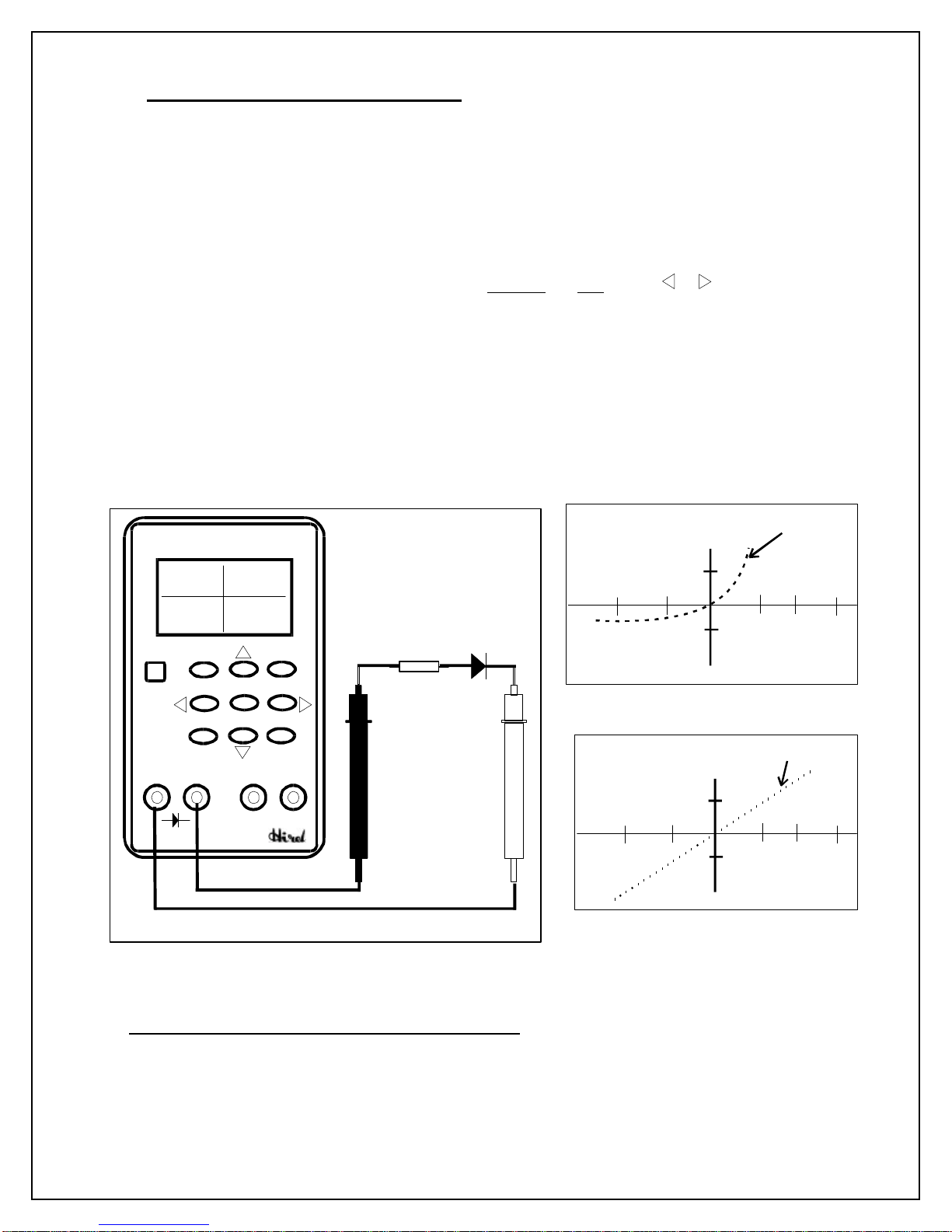
-G- Operating the HH972 in METER mode
This mode is useful to check a possibly damaged discrete or in-circuit component. It can also
help test resistors or trace open/shorts in failing systems.
To perform continuity testing, plug the black test lead into K-labeled black terminal. and the
red one into the A-labeled red terminal (as shown in Fig. 6).
Then, press the POWER button. Connect test leads across the component under measurement
through appropriate resistor ( 200Ω~ 1KΩrecommended) (see Fig. 6).
Press MENU to access MENU parameters, set DIODE to ON using / . The HH972
displays a new window as shown in Fig.7 and Fig.8.
Aand Kplugs become active with a sweeping voltage of +/-5V on Aplug, referenced to K
plug. I/V curve is now shown as illustrated by dotted line in Fig.7, for diode testing.
For resistor testing, the HH972 displays a linear curve and a rounded value in the bottom right
corner of the panel. (see Fig.8)
Warning: It is recommended to attach probes to semiconductor devices through a resistor for
current limitation (as shown in Fig.6).
5. ST972 STAND with rechargeable battery: (Fig.9)
The optional ST972 STAND is very useful to hold the scope vertically. It frees user’s hands
and provides 10-hours of operating time on the included rechargeable battery.
DIODE
I vs V curve
Y: 1mA
x; 2V
Figure 7
Pocket Scope
HH972
AK
COM
V
POWERAUTO HOLD
SELECT
MENU MODE
R
Diode
RUN
DIODE
Y : 1mA
X : 2V
Figure 6
DIODE
I vs V curve
Y: 1mA
x; 2V
R: 2K
Ω
Figure 8

HH972 Operating Manual p 10/12
Insert the HH972 unit into the ST972 holder,
making sure to properly align the registration pins
during the insertion (see Fig.10). Pins are positioned
to hold the scope in place. Then, plug the left-hand
side 9V battery output jack into the HH972
connector to get it powered (see Fig.11).
To charge the battery, connect the AC adapter to the
mains lines, plug the adapter jack into the right-
hand side connector. A red LED will turn-on until
the battery is fully charged. Then it naturally turns-
off when the battery is charged. (see Fig. 12)
Fig.10
Fig. 9
Fig.11
Fig.12

HH972 Operating Manual p 11/12
6. Specifications
Model HH972
Display Black and white EL backlit LCD type, 150(H) x 100(V) dots. Light is
turned on and off when the HOLD button is depressed longer than 2
sec each time.
Bandwidth DC to 5MHz. Digital sampling @20Ms/sec.
Display Resolution 6 bit to provide very smooth waveforms and text.
Vertical Range 50mV/div ~ 200V/div.
Horizontal Range 100nsec/div ~ 10sec/div.
Input Impedance 1Mohm (F= 1KHz).
Basic Functions ŸOSCILLOSCOPE mode, using COM and V terminals:
Automatic capture mode. Automatic display mode. Continuous peak
to peak measurement mode.
CURSOR / SCROLL / HOLD functions.
ŸMETER mode using Aand Kterminals:
I / V curves displayed.
Battery 9V alkaline battery (auto power-off in 10min for power saving)
Approx. 3-hour lifetime in continuous operation.
Size 3.6” x 7.1” x 1.4” (180 x 90 x 35 mm)
Weight 12.7 oz (360g) with battery.
AC power adapter 120V, 60 Hz or 230V, 50Hz
(INCLUDED) (No automatic power-off when the HH972 is used with AC power
adapter).
ST972 This Vertical Stand includes an approx. 10-hour rechargeable battery
Battery Stand with the AC adapter. It provides an easy way to handle the HH972
(OPTIONAL) and see the display. Size: 7.9" x 4.5 " x 3" (20 x 11.4 x 7.6 mm).
ST972-EC Basic stand as above with an event catcher electronic module for car
(OPTIONAL) ignition analysis. Associated with the stand, the HH972 catches the
ignition event sequence.
Temperature:
Operating 0°C ~ 40°C (below 80% RH) (32°F ~ 104°F)
Storage -10°C ~ 50°C (below 70% RH) (14°F ~ 122°F)
Max input voltage + or – 400V DC, 800V peak to peak AC.

HH972 Operating Manual p 12/12
for more informations, please contact:
MERIC TECHNOLOGY INC.
955 BERKSHIRE AVENUE, SUNNYVALE, CA 94087
TEL (1) 408-773-2767 FAX (1) 408-773-2781
e-mail: [email protected]
website: http://www.merictech.com
Notice
The information in this guide is subject to change without notice and should not be construed
as a commitment by the HIREL CORPORATION.
HIREL CORPORATION AND ITS REPRESENTATIVES SHALL NOT BE LIABLE FOR
TECHNICAL OR EDITORIAL ERRORS OR OMISSIONS CONTAINED HEREIN; NOR
FOR THE INCIDENTAL OR CONSEQUENTIAL DAMAGES RESULTING FROM THE
FURNISHING, PERFORMANCE, OR USE OF THIS DOCUMENT.
This manual suits for next models
1
Table of contents
Popular Test Equipment manuals by other brands


Benning
Benning PV 1-1+ Short instructions

Endress+Hauser
Endress+Hauser Nivotester FTL 370-F2E1 manual

ITE
ITE IT9500 Series user guide

MULTI MEASURING INSTRUMENTS
MULTI MEASURING INSTRUMENTS MIS-PV2 instruction manual

ScienTECH
ScienTECH Scientech 801C Learning Material

AlcoSense
AlcoSense Verity user manual


