manuals.online logo
Brands
  1. Home
  2. •
  3. Brands
  4. •
  5. Smartgen
  6. •
  7. Controllers
  8. •
  9. Smartgen HGM8100A User manual

Smartgen HGM8100A User manual

Other manuals for HGM8100A

1

This manual suits for next models

1

Other Smartgen Controllers manuals

Smartgen MGC100 User manual

Smartgen

Smartgen MGC100 User manual

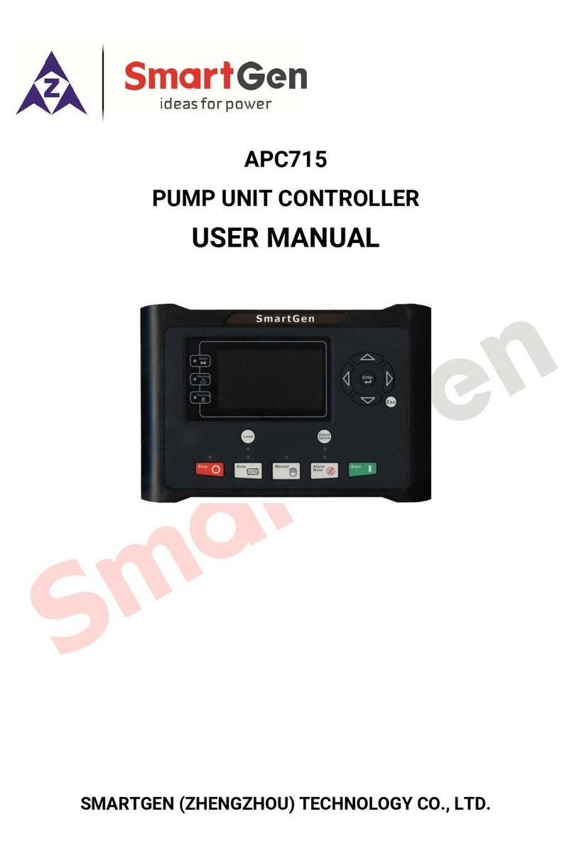
Smartgen APC715 User manual

Smartgen

Smartgen APC715 User manual

Smartgen ACC4100 User manual

Smartgen

Smartgen ACC4100 User manual

Smartgen HGM8156 User manual

Smartgen

Smartgen HGM8156 User manual

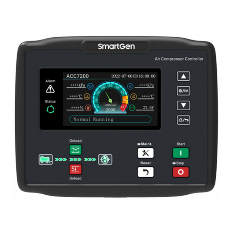
Smartgen ACC7200 User manual

Smartgen

Smartgen ACC7200 User manual

Smartgen HGM9560 User manual

Smartgen

Smartgen HGM9560 User manual

Smartgen HGM6100N Series User manual

Smartgen

Smartgen HGM6100N Series User manual

Smartgen HGM6510 User manual

Smartgen

Smartgen HGM6510 User manual

Smartgen GENSET CONTROLLER MGC310 User manual

Smartgen

Smartgen GENSET CONTROLLER MGC310 User manual

Smartgen HGM8110DC User manual

Smartgen

Smartgen HGM8110DC User manual

Smartgen HGM7110DC User manual

Smartgen

Smartgen HGM7110DC User manual

Smartgen HGM400N Series User manual

Smartgen

Smartgen HGM400N Series User manual

Smartgen HGM1780 User manual

Smartgen

Smartgen HGM1780 User manual

Smartgen HAT833 Series User manual

Smartgen

Smartgen HAT833 Series User manual

Smartgen HGM9120 User manual

Smartgen

Smartgen HGM9120 User manual

Smartgen HGM9420N User manual

Smartgen

Smartgen HGM9420N User manual

Smartgen HAT530 User manual

Smartgen

Smartgen HAT530 User manual

Smartgen HGM8110DC-2 User manual

Smartgen

Smartgen HGM8110DC-2 User manual

Smartgen HGM4020DC User manual

Smartgen

Smartgen HGM4020DC User manual

Smartgen HGM9310MPU Series User manual

Smartgen

Smartgen HGM9310MPU Series User manual

Smartgen HGM1790N User manual

Smartgen

Smartgen HGM1790N User manual

Smartgen HAT162 User manual

Smartgen

Smartgen HAT162 User manual

Smartgen HAT828 User manual

Smartgen

Smartgen HAT828 User manual

Smartgen HMU8-9570 User manual

Smartgen

Smartgen HMU8-9570 User manual

Popular Controllers manuals by other brands

Sunricher SR-ZV9003T3-RGBW-US Installation

Sunricher

Sunricher SR-ZV9003T3-RGBW-US Installation

Ksenia intro Installation and configuration manual

Ksenia

Ksenia intro Installation and configuration manual

Inovance CAN200 Series manual

Inovance

Inovance CAN200 Series manual

Gauzy LC6 FLEX Controller Installation and operation guide

Gauzy

Gauzy LC6 FLEX Controller Installation and operation guide

Viking SLP-1 Technical practice

Viking

Viking SLP-1 Technical practice

CKD KBX-30E-U Series instruction manual

CKD

CKD KBX-30E-U Series instruction manual

Sharp Energy Sun Flux User manual & installation guide

Sharp Energy

Sharp Energy Sun Flux User manual & installation guide

Yamaha RCX40 user manual

Yamaha

Yamaha RCX40 user manual

AB Quality PowerFlex 400 Frames D-H Service bulletin

AB Quality

AB Quality PowerFlex 400 Frames D-H Service bulletin

Yamaha MJC8 owner's manual

Yamaha

Yamaha MJC8 owner's manual

AL-KO ATC operating instructions

AL-KO

AL-KO ATC operating instructions

Savant SmartControl 2 Deployment guide

Savant

Savant SmartControl 2 Deployment guide

GameSir T3S user manual

GameSir

GameSir T3S user manual

Kostal inveor operating manual

Kostal

Kostal inveor operating manual

Emerson Yarway 20-55 Operating and safety instructions

Emerson

Emerson Yarway 20-55 Operating and safety instructions

CoCo ACM-LV24 Quick installation guide

CoCo

CoCo ACM-LV24 Quick installation guide

Brooks SLA5810/20 Installation and operation manual

Brooks

Brooks SLA5810/20 Installation and operation manual

SIGMA TEK SR 011 Technical manual

SIGMA TEK

SIGMA TEK SR 011 Technical manual

manuals.online logo
manuals.online logoBrands
  • About & Mission
  • Contact us
  • Privacy Policy
  • Terms and Conditions

Copyright 2025 Manuals.Online. All Rights Reserved.

HGM8100A GENSET CONTROLLER
(HGM8110A/HGM8120A)
(VFD DISPLAY)
USER MANUAL
SMARTGEN (ZHENGZHOU) TECHNOLOGY CO., LTD.
Chinese trademark
English trademark
SmartGen —make your generator smart
SmartGen Technology Co., Ltd.
No.28 Jinsuo Road, Zhengzhou, Henan Province, China.
Tel: +86-371-67988888/67981888/67992951
+86-371-67981000(overseas)
Fax: +86-371-67992952
Web: http://www.smartgen.com.cn
http://www.smartgen.cn
Email: sales@smartgen.cn
All rights reserved. No part of this publication may be reproduced in any material form (including
photocopying or storing in any medium by electronic means or other) without the written permission
of the copyright holder.
Applications for the copyright holder’s written permission to reproduce any part of this publication
should be addressed to Smartgen Technology at the address above.
Any reference to trademarked product names used within this publication is owned by their
respective companies.
SmartGen Technology reserves the right to change the contents of this document without prior notice.
Table 1 Software Version
Date
Version
Note
2013-01-29
1.0
Original release.
2013-04-12
1.1
Modify some details.
2013-06-17
1.2
Modify case dimension; Modify the contents of “Oil Pressure
Sensor”
2013-11-20
1.3
Add “Loss of Speed Signal Shutdown” in output port settings.
2013-12-23
1.4
Add function: Long pressing “ ” button can reset trip alarm.
2014-10-23
1.5
Change the “Working Conditions” and “Storage Condition”
temperature as (-40~+70)°C
2016-09-28
1.6
Modify the picture of mask and the graph of controller dimension.
2021-03-24
1.7
Modify the error in specification and other translation problems.
HGM8110A/8120A Genset Controller User Manual Page 3 of 57
This manual is suitable for HGM8110A/HGM8120A controller only.
Clarification of notation used within this publication.
Table 2 Notation Clarification
Sign
Instruction
NOTE
Highlights an essential element of a procedure to ensure correctness.
CAUTION!
Indicates a procedure or practice, which, if not strictly observed, could result in
damage or destruction of equipment.
WARNING!
Indicates error operation may cause death, serious injury and significant
property damage.
HGM8110A/8120A Genset Controller User Manual Page 4 of 57
CONTENT
1 OVERVIEW...............................................................................................................................................6
2 PERFORMANCE AND CHARACTERISTICS ...........................................................................................7
3 SPECIFICATION....................................................................................................................................10
4 OPERATION ..........................................................................................................................................11
4.1 KEY FUNCTION...............................................................................................................................11
4.2 INDICATOR LIGHT..........................................................................................................................12
4.3 LCD DISPLAY..................................................................................................................................13
4.3.1 MAIN DISPLAY................................................................................................................... 13
4.3.2 BASIC PARAMETER SETTING MENU............................................................................... 14
4.3.3 ADVANCED PARAMETERS SETTING ............................................................................... 16
4.4 AUTOMATIC START/STOP OPERATION ......................................................................................18
4.5 MANUAL START/STOP OPERATION ............................................................................................19
4.6 GENSET CONTROLLER ATS CONTROL PROCEDURES ...............................................................20
4.7 VIEWING EVENT LOG.....................................................................................................................21
5 PROTECTION ........................................................................................................................................22
5.1 WARNING........................................................................................................................................22
5.2 SHUTDOWN ALARM ......................................................................................................................24
5.3 TRIP AND STOP ALARM................................................................................................................26
5.4 TRIP ALARM ...................................................................................................................................26
6 WIRING CONNECTION .........................................................................................................................27
7 SCOPES AND DEFINITIONS OF CONFIGURABLE PARAMETERS......................................................30
7.1 CONTENTS AND SCOPES OF PARAMETERS...............................................................................30
7.2 ENABLE DEFINITION OF PROGRAMMABLE OUTPUT PORTS 1-6 ..............................................38
7.2.1 DEFINED CONTENTS OF PROGRAMMABLE OUTPUT PORTS 1-6 ................................. 38
7.2.2 CUSTOM PERIOD OUTPUT ............................................................................................... 42
7.2.3 CUSTOM COMBINED OUTPUT ......................................................................................... 42
7.3 DEFINED CONTENTS OF CONFIGURABLE INPUT PORTS 1-6 ....................................................44
7.4 SELECTION OF SENSORS..............................................................................................................47
HGM8110A/8120A Genset Controller User Manual Page 5 of 57
7.5 CONDITIONS OF CRANK DISCONNECT SELECTION...................................................................48
8 PARAMETER EDITING..........................................................................................................................49
9 SENSORS SETTING ..............................................................................................................................51
10 COMMISSIONING .................................................................................................................................52
11 TYPICAL APPLICATION .......................................................................................................................53
12 INSTALLATION .....................................................................................................................................55
12.1 BATTERY VOLTAGE INPUT ...........................................................................................................55
12.2 SPEED SENSOR INPUT ..................................................................................................................55
12.3 OUTPUT AND EXPAND RELAYS....................................................................................................55
12.4 AC INPUT........................................................................................................................................55
12.5 WITHSTAND VOLTAGE TEST........................................................................................................56
13 FAULT FINDING ....................................................................................................................................57
HGM8110A/8120A Genset Controller User Manual Page 6 of 57
1
OVERVIEW
HGM8110A/8120A genset controllers are especially designed for extremely high/low temperature
environment (-40~+70)°C. The controllers can operate reliably in extreme temperature conditions
with the help of VFD display and the components that resist extreme temperature. All display
information is Chinese (English is optional). Operation information, status information and faults
information are all displayed which make commissioning convenience for factory personnel.
Controller can be used under complex electromagnetic interference environment with the strong
ability of anti-electromagnetic interference. Easy to maintain and upgrade due to the plug-in terminal.
HGM8110A/8120A genset controllers integrate digitization, intelligentization and network
technology which are used for genset automation and monitor control system of single unit to
achieve automatic start/stop, data measuring, alarm protection and “four remotes” (remote control,
remote measuring, remote communication and remote regulating).
HGM8110A/8120A genset controllers adopt micro-processor technology with precision parameters
measuring, fixed value adjustment, time setting and threshold adjusting and etc. Majority
parameters can be configured from front panel, and all parameters can be configured by RS485
interface (or RS232) to adjust via PC. It can be widely used in all types of automatic genset control
system with compact structure, advanced circuits, simple connections and high reliability.
HGM8110A/8120A Genset Controller User Manual Page 7 of 57
2
PERFORMANCE AND CHARACTERISTICS
♦HGM8100A series controller has two types:
HGM8110A: ASM (Automatic Start Module), used for single automation systems;
HGM8120A: AMF (Auto Mains Failure), updates based on HGM8110A, moreover, has mains
electric quantity monitoring and mains/generator automatic transfer control function, especially
for automatic system composed by generator and mains;
♦With ARM-based 32-bit SCM, highly integrated hardware, new reliability level;
♦Vacuum fluorescent display (VFD), selectable Chinese/English interface which can be chosen at
the site, making commissioning convenience for factory personnel;
♦Widely temperature range: (-40~+70)°C, can be used in extreme temperature environment;
♦Suitable for 3-phase 4-wire, 3-phase 3-wire, single phase 2-wire, and 2-phase 3-wire systems with
voltage 120/240V and frequency 50/60Hz;
♦Collects and shows 3-phase voltage, current, power parameter and frequency of generator or
mains;
Mains
Line voltage (Uab, Ubc, and Uca) V (unit)
Phase voltage (Ua, Ub, and Uc) V (unit)
Frequency f Hz (unit)
Generator
Line voltage (Uab, Ubc, and Uca) V (unit)
Phase voltage (Ua, Ub, and Uc) V (unit)
Frequency f Hz (unit)
Load
3-phase Current Ia, Ib, Ic A (unit)
Active power (P) kW (unit)
Apparent power (S) kVA (unit)
Power factor (λ)
Accumulate total generator power (W) kWh (unit)
♦For Mains, controller has over and under voltage, over and under frequency, loss of phase and
reverse phase sequence detection functions; For generator, controller has over and under voltage,
over and under frequency, over current, over and reverse power, loss of phase, reverse phase
sequence detection functions;
♦3 fixed analog sensors (temperature, oil pressure and liquid level);
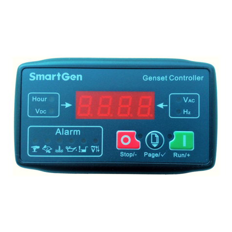
HGM8110A/8120A Genset Controller User Manual Page 8 of 57
♦2 configurable sensors can be set as sensor of temperature, oil pressure or fuel level;
♦Precision measure and display parameters about Engine,
Temp. (WT) °C/°F both be displayed
Oil pressure (OP) kPa/psi/bar all be displayed
Speed (RPM)
Voltage of Battery (VB) V (unit)
Voltage of Charger (VD) V (unit)
Hour count (HC) can accumulate to max. 65535 hours.
Start times can accumulate to max. 65535 times.
♦Protection: automatic start/stop of the gen-set, ATS (Auto Transfer Switch) control with perfect
fault display and protection function;
Fault display and protection items:
High temperature alarm
High temperature shutdown
Low oil pressure alarm
Low oil pressure shutdown
Over speed shutdown
Low fuel level warn
Battery voltage high warn
Battery voltage low warn
Load over current shutdown
Fail to start alarm
Fail to stop alarm
Emergency stop alarm
Oil pressure sensor open circuit alarm
Temperature sensor open circuit alarm
♦All output ports are relay-out;
♦Parameter setting: parameters can be modified and stored in internal EEPROM memory and
cannot be lost even in case of power outage; most of them can be adjusted using front panel of
the controller and all of them can be modified using PC via RS485/RS232 ports;
♦More kinds of curves of temperature, oil pressure, fuel level can be used directly and users can
define the sensor curves by themselves;
♦Multiple crank disconnect conditions (speed sensor, oil pressure, generator frequency) are
optional;
HGM8110A/8120A Genset Controller User Manual Page 9 of 57
♦Real time clock and run time accumulation function. 99 pieces of event logs can be circularly
stored and inquired on the spot; also can be print or be inquired via PC;
♦Scheduled start & stop generator (can be set as start genset once a week/month);
♦With maintenance function. Actions (warning, shutdown or trip and stop) can be set when
maintenance time out;
♦Can be used on pumping units and as an indicating instrument (indicate and alarm are enable
only, relay is inhibited);
♦Accumulative total electric energy. Users can reset it and re-accumulate the value which make
convenience to users to count the total value as their wish;
♦Widely power supply range: DC (8~35)V, suitable to12/24V starting battery voltage environment;
♦With international standard MODBUS communication protocol, better error checking capability,
and with RS232 and RS485 (coupling isolation) communication interface, can realize functions of
remote control, remote measuring, remote communication and remote regulating, facilitate
remote centralized monitoring of genset;
♦Waterproof security level IP55 due to rubber seal installed between the controller enclosure and
panel fascia;
♦Metal fixing clips enable perfect in high temperature environment;
♦Modular design, pluggable connection terminals and embedded installation way; compact
structure with easy mounting.
HGM8110A/8120A Genset Controller User Manual Page 10 of 57
3
SPECIFICATION
Table 3 Technical Parameters
Item
Content
Operating Voltage
DC8. 0V to 35. 0V, Continuous Power Supply
Power Consumption
<6W (Standby mode: ≤3W)
Alternator Input Range
3-Phase 4 Wire
3-Phase 3 Wire
Single-Phase 2 Wire
2-Phase 3 Wire
AC20V - AC360V (ph-N)
AC30V - AC600V (ph-ph)
AC20V - AC360V (ph-N)
Alternator Frequency
50Hz/60Hz
Speed Sensor Voltage
1.0V to 24.0V (RMS)
Speed Sensor Frequency
10,000 Hz (max)
Start Relay Output
16A DC28V at supply output
Fuel Relay Output
16A DC28V at supply output
Aux. Output 1
16A DC28V at supply output
Aux. Output 2
16A DC28V at supply output
Aux. Output 3
16A DC28V at supply output
Aux. Output 4
16A AC250V passive
Gen Close Relay
Aux. Output 5
16A AC250V passive
Mains Close Relay
Aux. Output 6
16A AC250V passive
Overall Dimensions
243.7mm x 176.2mm x 51.2mm
Panel Cutout
214mm x 160mm
C. T. Secondary
5A (rated)
Working Conditions
Temperature: (-40~+70)°C Humidity: (20~93)%RH
Storage Condition
Temperature: (-40~+70)°C
Protective Level
IP55 Gasket
Insulation Intensity
Apply AC2.2kV voltage between high voltage terminal and low
voltage terminal;
The leakage current is not more than 3mA within 1min.
Weight
0.80kg