Chapter 2 Identifying External Components
This chapter describes the front panel, rear panel and LED indicators of the Switch.
2.1 Front Panel
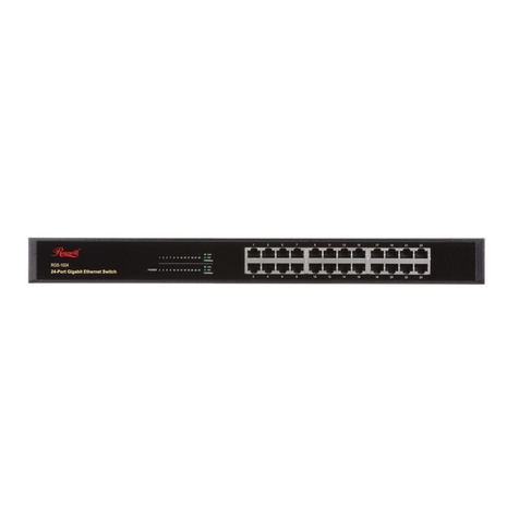
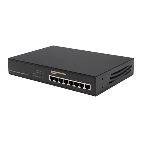
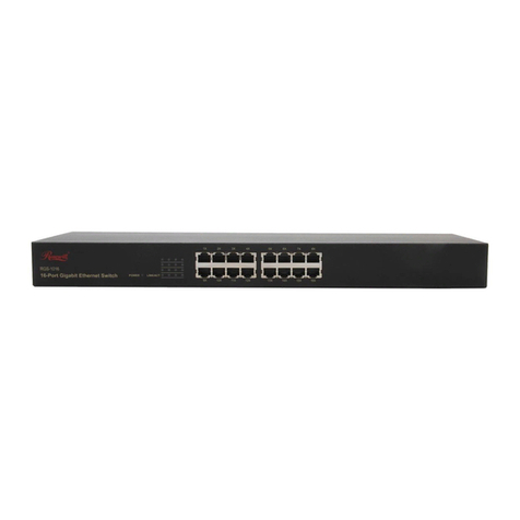
The front panel of RC-GS1024 consists of switch model, switch LED indicators,
and 24 10/100/1000Mbps RJ45 ports.
Figure 2-1 Switch Front Panel Sketch
The LED indicators include Power, Link/Act and 1000Mbps LED indicators, which
are used for monitoring and pre-troubleshooting of the Switch. The following
section shows the LED indicators of the Switch along with an explanation of each
indicator.
Power LED: This indicator will light solid green when the Switch powers up.
If the LED is not lit, please check the power supply and connection.
Link/Act LED: The LED indicates Link/Active status. The corresponding LED
indicator will light solid green when connected to a network device. It flashes
green when data is being transmitted or received on the working connection.
1000Mbps LED: The indicator will light solid green when the
corresponding port is working on 1000Mbps speed. If the LED is off, it
is working on 10/100Mbps speed or no device is connected.
2.2 Rear Panel
The rear panel of RC-GS1024 features a power socket and a Grounding Terminal
(marked with ).
Figure 2-2 Switch Rear Panel Sketch
Grounding Terminal: RC-GS1024 already comes with Lightning Protection
Mechanism. You can also ground the Switch through the PE (Protecting Earth)
cable of AC cord or with Ground Cable. For detail information, please refer to
section 3.3 Connect to Ground.
AC Power Socket:Connect the female connector of the power cord here, and
the male connector to the AC power outlet. Please make sure the voltage of
the power supply meets the requirement of the input voltage.
4
